|
Contents:
|
|
|
Contents:
|
|

|

|
|
When my wife and I had just met, now nearly eighteen years ago, we spent a few fantastic holidays camping and travelling by car in Great-Britain. It has been a longstanding wish to return to the beautiful countryside of Britain, but for a number of personal reasons that has been difficult the past years. But this year it finally happened, the children were old enough to appreciate the trip, dogs were allowed to travel the
 channel (be it after a lot of paper work), and we had something to celebrate! After a lot of searching my wife found a beautiful cottage in the charming center of Old-Hastings, Sussex. Old-Hastings is ancient with many houses dating from the 15th and 16th century situated between two clift at walking distance from the beach with many (Fish) restaurants, nice shops and pubs. I think I could spend a whole page describing all the attractions and sights in and around Hastings, but I will limit myself to one specific treat I enjoyed in particular. Every morning, while my wife was till sleeping, I first walked the dog on the greens on top of the cliffs. It is amazing how green and free of litter the grass is on those hills! Coming from Holland, which is extraordinarily flat, the view of the beach from the cliffs is amazing.
After my walk with the dog, I would go to the beach and watch in the mild May sun the fishers boats being towed on and off the beach. At around nine when the coffee-bars opened I would go to the corner of George Street and High street and enjoy a cappuccino in ōThe Corner Coffee Shop,ö absorbed in Mark FranklandÆs ōRadio Manö [1]. What a delight!
channel (be it after a lot of paper work), and we had something to celebrate! After a lot of searching my wife found a beautiful cottage in the charming center of Old-Hastings, Sussex. Old-Hastings is ancient with many houses dating from the 15th and 16th century situated between two clift at walking distance from the beach with many (Fish) restaurants, nice shops and pubs. I think I could spend a whole page describing all the attractions and sights in and around Hastings, but I will limit myself to one specific treat I enjoyed in particular. Every morning, while my wife was till sleeping, I first walked the dog on the greens on top of the cliffs. It is amazing how green and free of litter the grass is on those hills! Coming from Holland, which is extraordinarily flat, the view of the beach from the cliffs is amazing.
After my walk with the dog, I would go to the beach and watch in the mild May sun the fishers boats being towed on and off the beach. At around nine when the coffee-bars opened I would go to the corner of George Street and High street and enjoy a cappuccino in ōThe Corner Coffee Shop,ö absorbed in Mark FranklandÆs ōRadio Manö [1]. What a delight!
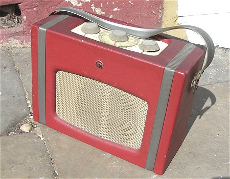
Before we left, I had agreed with myself to keep my eyes open for a nice vintage tube radio, preferably from Pye. At the time of the trip I was researching the history of Pye for my page on the history of the EF50 tube,. One way or the other Pye Radio, with its very out of the ordinary, outspoken and extravagant director C.O. Stanley had caught my fascination, and I thought it would be great to take something from Pye back to Holland as a souvenir, although I realized that the actual chance of finding such a treasure on such a short holiday would obviously be very small. Now for some reason there are literally dozens of second-hand and antique shops in Old-Hastings. Most of them have really nice stuff. I think it was the second of third day of our holiday when my son Geert and I returned from a nice walk on the greens on the East Hill when we passed one of the these antique shops in Courthouse Street. It was a strange shop, more a kind of courtyard filled with shops or sometimes even sheds from a handful of antique dealers. Geert, who is not that interested in antiques, went ahead with the dog, and I went in to have a look. And there it was! A beautiful Pye battery portable! I immediately recognized it from a picture on the cover of Mark FranklandÆs ōRadio Man.ö What a coincidence! Apart from the fact that unfortunately the back cover was missing it was otherwise in pretty fair condition! There was only very little rust but most importantly, all the tubes were there. The best thing of all: it was only fifteen pounds, an unbelievable bargain! I immediately grabbed it and triumphantly went to the owner of the shop, if you can call an old garage filled with antiques and old-stuff a shop. A was a colorful character with a straw hat, and I am sure that when he saw the twinkling in my eyes, he realized that he had charged me too little.
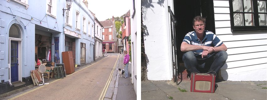
Figure 1. The ōantiquesö shop in Courthouse Street, Old Hastings, where I bought the P87BQ (left), and its proud owner in front of the Cottage we rented in Church Passage.
At this point I have to explain my fascination for battery tubes. I inherited my love and enthusiasm for electronics from my father. My father was a war-child. He had a pretty miserable childhood, and during the war there was a shortage of almost everything. The only radio the family of my father had during the war was a simple homebuilt christal-set receiver which they had to hide because radios were forbidden by the Germans. This explains my fatherÆs fascination for small and portable radio and later television sets. A few years after the war, Philips introduced several ōline-upsö of battery tubes, in the small miniature envelope that the Americans had developed during the war. Fascinated by the possibility of building a small portable radio with these tubes, my father saved more than a monthÆs wages to buy such a set of battery tubes. Hot from enthusiasm and anticipation, he built the small radio, but then he made a terrible mistake: eager to try the radio he accidentally exchanged the 1.5 filament battery with the 45 V anode battery. It meant an instant death for the tubes and a loss of a months wages. There was no money for new tubes, and the radio never worked. I still remember how he told me this story when I was a child, and I remember how, as a child, I already felt deeply sorry for him. My father has never been very lucky in life, and this was just one of those sad moments. A consequence of this whole affair was that I myself got stuck with a fascination for these nice small tubes and whenever I find one, I feel as if I have won a prize. I have a nice small collection of these tubes, and I wish sometimes that my father was still around to see them.

Figure 2. Panoramic view from the West Hill in Hastings.
| to top of page | back to homepage |
Although I am not a vintage radio specialist at all, I happen to see from time to time some old radio sets. Being a Dutchman, most of these sets are made by Philips, so I am used to what may be called ōthe Philips styleö of making radios. It was to me a bit of a surprise that this British Pye set had such a completely different look. I was pleasantly surprised by the mechanical robustness and the neatness of the whole assembly, which was in the well known ōbirdÆs nestö style. For all the longer wires color coded flexible wires were used. Underneath the chassis, also color coded wires were used for the interconnects, while the longer leads of the components were neatly isolated with colored plastic isolation tubing. The tuning capacitor and the volume potentiometer looked very robust and of high quality.
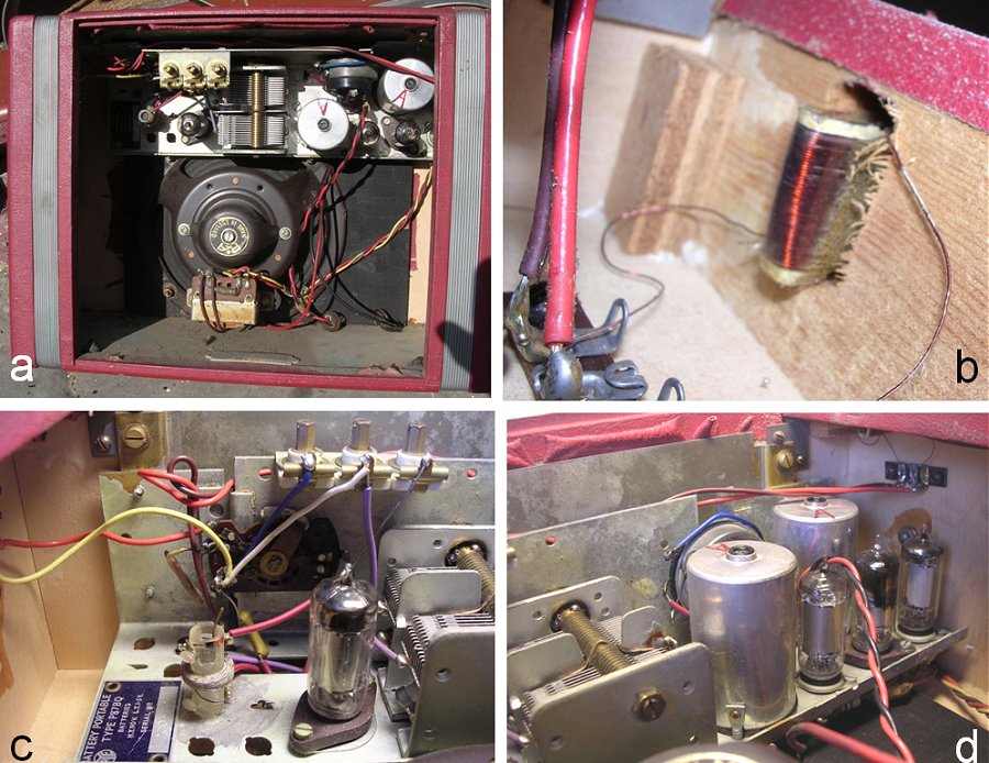
Figure 3. Some pictures of the interior of the P87BQ in the state I bought it. Figures C and D show the tube line-up from left to right (Fig. C) the DK96 RF amplifier/mixer, (Fig. D) the DF96 IF amplifier, DAF96 detector AF preamplifier and DL96 output pentode.
What struck me was the different look of the resistors and capacitors compared to what I am used to from Philips sets. We live in a time where everything is global, and distances seem to have disappeared. The number of component manufacturers seems to have been reduced to only a hand full mainly located in Asia. Components have been standardized, and look the same all over the world. This was certainly not the case some fifty years ago. Every country had their own component and set makers, and in many cases even more than one! Although most of the components at first sight looked pretty ok, there were some wax coated tubular capacitors which looked very dirty, greasy and even sticky.
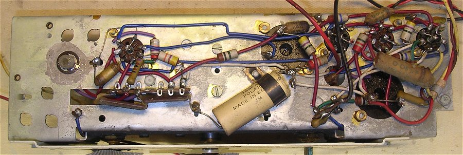
Figure 4. The bottom-side of the chassis after removal from the carrying case.
What was striking was the absence of a Ferrite rod antenna. Philips pioneered the development of Ferrites and held some very important patents in this area. In Philips radios of that time already ferrite core antennas were used because they provided a higher sensitivity and were smaller than a frame antenna such as was used in this receiver. The frame antennas are located in two slots at opposite sides of the carrying case underneath the two ribbed plastic strips. One of the frame antennas is for the medium-wave band and when both antennas are switched in series, the long-wave band is covered. Figure 3B was taken with the camera inside the carrying box, showing the point where the frame antenna enters the carrying box. Apparently the antenna is winded on a paper or carton strip first and then glued in the wooden case. The slot in the wooden case is used to tighten the antenna around the case. It must have been quite a labor intensive procedure altogether.
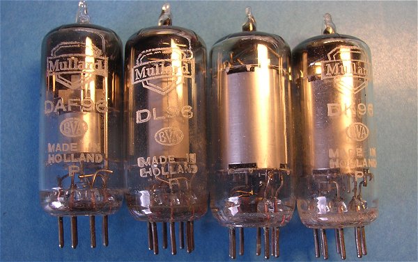
Figure 5. The valves of the P87BQ stamped Mullard, B.V.A. (British Valve Association) and Made in Holland. A strange combination!
I was lucky to be able to download the ōTrader service sheetö for free from www.savoy-hill.co.uk [2]. I also downloaded the official Pye service datasheet from www.service-data.com for a small fee, but this didnÆt contain any new information. The ōTrader Service Sheetö contains a lot of useful information. Besides the circuit diagram, it gives a description of the circuit, the procedure for the circuit alignment, and very useful, the anode and screen grid voltages and currents.
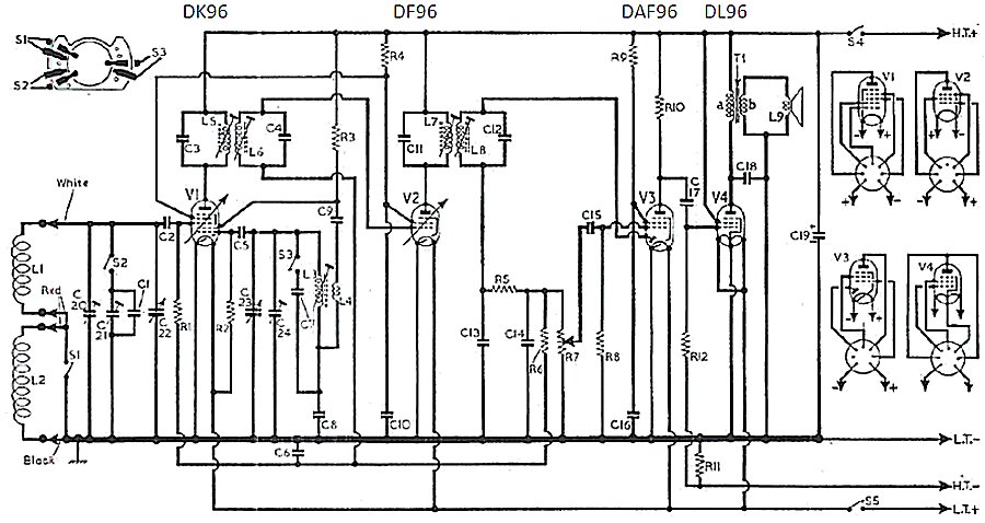
Figure 6. Circuit diagram taken from the ōTrader service sheetö [2]
The circuit itself is pretty straightforward. A line-up like the Dx96 series was designed by Philips/Mullard for a certain basic circuit configuration, and the set-maker could then add some features like tone-control or multiple band coverage. The DK96 heptode (V1) is used as a classical RF amplifier and mixer. For the medium-wave band switch S1 is closed (low inductance), while S2 and S3 are open (low capacitance). For the long-wave band S1 is opened (both frame antennas in series) while S2 and S3 are closed. The Intermediate Frequency (IF) is 470 kHz and the IF signal is amplified by a DF96 (V2). The diode section of V3 (DAF96) rectifies the IF amplified signal by short circuiting its positive portion to ground via the diode in V3. This will result in a negative DC voltage across C14 onto which the AC audio signal is super-imposed. This signal is further smoothed by R6 and C6 and used for the automatic gain loop (AGC). A large signal, results in a more negative feedback voltage, which in turn reduces the bias on the control grids of V1 and V2 and hence reduces the gain (V2 is a variable-mu pentode). The audio signal is finally amplified by V3 (DAF96) and V4 (DL96). The negative control-grid bias for V4 is obtained from the voltage drop of the total current drawn from the anode battery over resistor R11. With a total current of slightly less than 10mA and a resistance value for R11 of 470 ohm the grid bias of V4 amounts to -4.5V. Since by this trick the rest of the circuit is fed through R11, the high voltage supply for the circuit itself has to be adequately decoupled which is done with battery reservoir capacitor C19.
| to top of page | back to homepage |
As mentioned before, the set was in a reasonable condition but badly needed some cleaning and degreasing. Since I wanted to inspect the circuit anyway, I first removed the chassis from the carrying case. This could be simply done by disconnecting the wires to the frame antennas and the output transformer and by removing two screws which fasten the chassis to the wooden case.
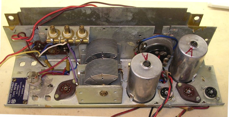
Figure 7. The chassis ready for cleaning
The chassis was a bit dirty and greasy, but fortunately didnÆt show any signs of rust. Especially the components and wires on the bottom side of the chassis were dirty (Fig. 4). The underside of the IF coils were greasy as if the grease that was used for the ferrite core inside had found its way to the bottom under intense heat. The whole set by the way looked as if it had been stored on a very hot place. The plastic knobs had even warped, and to some extend lost their original shape (Fig. 8). The grease and dirt were easily removed with some alcohol (Spiritus) and cotton-tips.
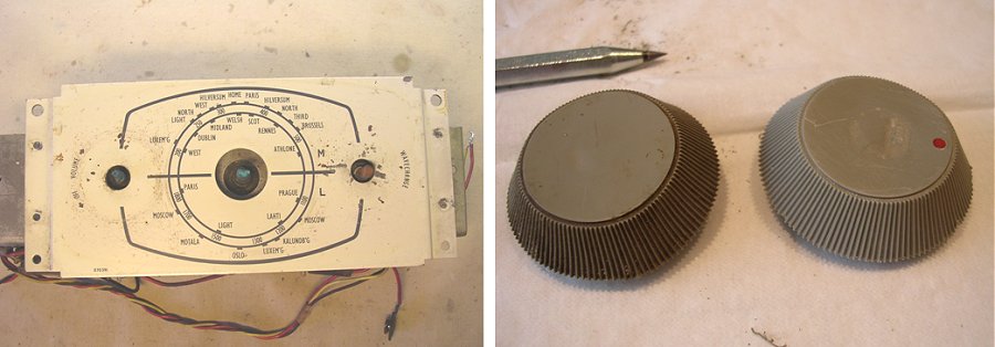
Figure 8. The ōdial-plateö before cleaning (left) and one of the knobs before and after cleaning (right).
Next, the knobs were removed from the axis of the controls. This was a bit difficult since everything was very dry and a bit rusty. Quite some force had to be used, and it is a small miracle that nothing broke. After removal of the knobs the front, or if you like top-plate could be removed. Unfortunately, intensive use of the set over the years had left its traces. After removal of dirt and grease the front plate showed quite some scratches, but fortunately not to such an extent that it immediately draws the attention. I have considered touching up the spots with a bit of paint, but I think I will leave it this way because it also gives it a bit of an authentic look.
The knobs were very dirty, especially the ribbed edges. With a sharp needle every groove was cleaned individually and the whole thing was given a good rub-over with an old toothbrush and some soap. The result was that they looked like new. The Plexiglas tuning dial was heavily scratched. With the help of a soft cloth and some good old Brasso metal polish and a bit of patience, it was possible to remove most of the scratches. The same treatment was used for the metal hinges that hold the plastic carrying band. After a good vacuum clean of the interior, the P87BQ was in a very acceptable state again.
| to top of page | back to homepage |
After cleaning the chassis, it was time to try to get some music out of the old beauty. A first quick check showed that the filaments of the four tubes were still intact and were drawing the nominal filament currents. Although this tells nothing about the emission of the filaments and/or other defects it is a good start.
When dealing with vintage high-voltage equipment, it is always a good idea to be a bit careful in switching on the high-voltage for the first time. The main causes for problems here are leaky or even short-circuited (electrolytic) capacitors. Especially electrolytic capacitors are notorious. For the dielectric, they rely on a very thin layer of Aluminum oxide. When an Electrolytic capacitor has not been used for a long time, this thin layer of Aluminum oxide is reduced in thickness. When all of a sudden the capacitor is charged to its maximum voltage, it may draw a (for the capacitor) lethal current. Fortunately it is in most cases possible to restore the thin dielectric layer in the electrolytic capacitor. This process is called ōforming.ö The process requires a variable high voltage source a resistor and some patience.
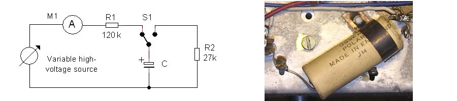
Figure 9. Simple circuit for forming electrolytic high-voltage capacitors (left) and battery reservoir capacitor C19 (right).
The circuit I use to form electrolytic capacitors is depicted in Fig 9 (left). With the switch in the position as drawn in the figure, the high voltage source is connected to the capacitor via R1. I usually start by setting the high voltage to a small value say 30V. If the capacitor is still ok, the current will first jump up, but as the capacitor charges decrease to almost zero. I always wait until the current drops to a value below a few micro-amps. It is interesting to note how much time this takes. Inside the capacitor the thin oxide layer is now starting to be restored. Next the capacitor is discharged through R2. The process is repeated with a higher voltage, until in steps the maximum rated voltage of the capacitor is reached. The forming process can be checked by charging the capacitor to the first voltage used in the forming process. If everything is ok, the time needed for the current to decrease to a few micro-amps should now be only a fraction of the original time it took.
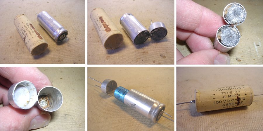
Figure 10. Replacing the old electrolytic capacitor with a new one.
Unfortunately, the original electrolytic capacitor in the P87BQ was already damaged beyond repair. Already at the lowest voltage the current just wouldnÆt decrease below a few hundred micro-amps. To keep the look of the radio as authentic as possible, I hid the new buffer capacitor in the old capacitor. A neat little trick that I copied from the many other sites which deal with restoring old vintages radio sets. But beware, although the replacement capacitor was relatively new, it still needed forming!
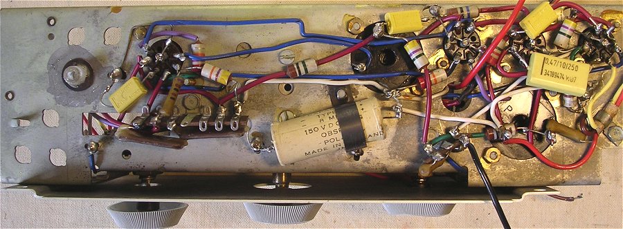
Figure 11. The chassis cleaned and with new capacitors.
With the reservoir capacitor replaced it was time to insert the tubes again and try the set! A 1.5 A-type battery was used for the filaments, while the high voltage terminals were connected to my variable high-voltage supply. With both voltages applied the set remained absolutely silent while the total high voltage current was way too high: 22mA instead of the 9.5mA specified in the service sheet. This could only be caused if one of the tubes, in particular the output valve V4 was drawing too much current, and that could only be caused if the tube was defect or if the control voltage was too high. A quick check revealed that the control grid voltage was about 5V positive, while it should have been 4.5V negative. It was not difficult to deduce that this could only be caused if DC blocking capacitor
 C17 was leaking, which proved to be the case. It was one of those sticky, greasy looking capacitors. Paul Stenning on his UK Vintage
Radio Repair and Restoration Site states that this type of capacitors often give problems [3]. For this reason I decided to replace all capacitors of this type with modern ones. Low and behold, the radio now produced some sound, and it was even possible to listen to several radio stations, although the sound was spoilt by a nasty rattle.
C17 was leaking, which proved to be the case. It was one of those sticky, greasy looking capacitors. Paul Stenning on his UK Vintage
Radio Repair and Restoration Site states that this type of capacitors often give problems [3]. For this reason I decided to replace all capacitors of this type with modern ones. Low and behold, the radio now produced some sound, and it was even possible to listen to several radio stations, although the sound was spoilt by a nasty rattle.
Finding the origin of the rattle proved to be a bit more difficult. Before going deep into the circuit of the radio itself, I wanted to eliminate the possibility that it was some external cause which caused the rattle. My ōknutselkamerö (radio shack) is filled with equipment which might cause interference one way or the other. However, with everything shut-off, the rattle was there just as bad. Next I wanted to be sure that it was not some fault in the tubes themselves. So one by one all four tubes were replaced. Fortunately, I have a whole set of spare tubes in my collection! Also this didnÆt prove to be the cause. The next question was, does the sound originate from the audio section or from the RF section. After removal of V1 and V2 the rattle was gone. So the audio part was ok. Also after IF amplifier tube V2 was replaced, the receiver remained quiet. However, as soon as V1 was in place again, the noise returned. To test the radio I had connected the frame antennas and the speaker with some 50cm length wires. Could it just be that these long wires picked up the noise or caused some oscillations? To eliminate this
possibility the chassis was placed back in the carrying case, and the original wires were attached. Again, no result. And then I thought I noticed something strange. I had the impression that when I switched my external high voltage supply off, the rattle disappeared
immediately, while the radio continued playing for another fraction of a second. Could it just be so simple that my Delta E0300-01 high voltage supply introduced the noise? I had always assumed that it Delta supply was just a simple linear supply, but perhaps it had a switching pre-regulator? I quickly switched a number of normal power supplies in series and connected them to the radio HV input and low and behold, the rattle was gone and the set produced a nice and warm sound, be it with a typical AM crackle!
| to top of page | back to homepage |

Does anybody have the English version?
A very nice and comprehensive overview of the history of the development of Battery Tubes at Philips / Mullard can be found in the general Introduction of a Philips Publication from the fifties called ōRadiobuizen voor Batterijontvangersö (Radio Tubes for Battery Receivers) by E. Rodenhuis. Unfortunately the book is, as far as I know, only available in Dutch. Since this history is rather interesting, I will (try to) give an English summary in this section.
æNow that battery receivers are becoming popular again, the ōold-timerö undoubtedly will think back of the time when all radios were battery receivers, and when everybody wanted to get rid of those troublesome and expensive batteries and accumulators. Especially the lead accumulator often needed recharging, since the filament current for the bright burning tungsten filaments of the first radio tubes was very high. A total filament current for a four valve radio of 2 to 4 Amps was quite normal. The anode batteries didnÆt need to supply such a large current since the emission of the first valves was very low, usually something in the order of 1 mA. It is therefore no wonder that tube manufacturers tried to make more efficient valves and quickly introduced main fed power supplies.
In the context of this general introduction it is worthwhile to mention two early methods that were used to reduce the power consumption of radio receivers. The first method was the use of so called ōsoft vacuumö tubes. These tubes, which were filled with a low-pressure argon gas already reached a quite acceptable plate current at plate voltages of 12-20V. [What happened was that the emitter electrons ionized argon atoms on their way to the anode. The new electrons in turn ionized other argon atoms etc. The advantage was that this obviously increased the anode current and thus the trans-conductance. The disadvantage was that the positively charged argon ions were attracted to the grid where thay caused a negative grid current. These tubes functioned fine as detectors, but were difficult to bias as amplifiers.] The second method used ōdouble-gridö tubes. By applying a small positive bias to an additional grid between the cathode and the control grid, it was possible to suppress the space charge surrounding the cathode resulting in a high plate current at low voltages.
The mainstream development however, was aimed at the fabrication of filaments (cathodes) that could give a high emission at low filament powers. It was Philips who took the lead in this development with the introduction of the ōMiniwattö series. Here the filaments were coated with a layer of barium resulting in a much higher emission. The total filament current for a radio with these tubes was something in the order of 300 to 400 mA.
Not long after the introduction of these barium coated filaments, the indirectly heated cathode was introduced to enable filaments to be directly powered by an AC voltage from the mains transformer. The intense research into the indirectly heated cathode delayed the further development of battery tubes. It took until 1938 when this development was taken up again resulting in several generations of battery tubes of which the D96 series is now the last member. In this latest generation of battery tubes, the filament thickness is reduced to 11um, while the total filament current for a four valve radio is reduced to a mere 125mA. It is not likely that it will be possible to reduce the power consumptions of battery tubes even further.
Chronological description of the development of low-power battery tubes at Philips/Mullard.
The first tubes with a reduced power consumption were the A410, A409, B406, and B403. These tubes were designed to be used in combination with a 4V lead-acid accumulator. There was a corresponding series of tubes for 2V accumulators (A210, ...) and a series to be used with a 1.5V Leclanchķ cel. (A110, ...). These tubes were built on a pinch with a horizontal electrode construction. This was necessary for the process that was used to cover the filament with a thin layer of bariumoxide. This process, the bariumazide process was developed at Philips Research. In the process the tungsten filament was copper plated and oxidized before the wire was mounted in the electrode assembly. Before evacuation a few drops of bariumazide (BaN6) were dispensed in a fine mesh which was located on the anode. When the tuba was evacuated and RF heated, the bariumazide decomposed. The barium deposited on the inside of the tube wall and the electrode components including the filament. There it reacted with the copperoxide to form bariumoxide. The layer of barium on the filament was extremely sensitive to gas contamination, especially Chlorine. For these barium coated tubes therefore a ōhard vacuumö had to be used. Whereas the uncoated brightly burning filaments tended to increase the vacuum while they were burning, this was certainly not the case for the barium coated tubes. It therefore became necessary to introduce a ōgetter.ö During gettering a small container with some magnesium is RF-heated so that the magnesium evaporates. The evaporated magnesium reacts with gases present in the tube and condenses as a shiny metallic layer on the inner glass surface. Much later it was discovered that it was not the magnesium, but the barium which predominantly acted as getter in this type of tubes. The expensive bariumazide process was used until 1934. Some of the last tubes which were fabricated with this process were the A452, A409 and the (for that time) very high mutual conductance tubes A415, B405, and B408. This series was later complemented with the RF tetrode A442 and the power penthode B443. Then came the time when the focus shifted to indirectly heated cathodes which moved the development of battery tubes to the background.
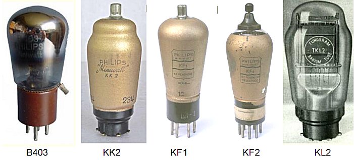
Figure 12. Some representatives from the first and second generation of battery tubes.
In the mean time the so called ōdrag-coatingö process was developed in the US. In this process, a thin nickel filament wire is coated with a layer of barium and strontium carbonates by dragging the wire through baths containing solutions of these carbonates, after which the wire was sintered. The first series of tubes made with the Philips version of the process were the octode KK2, RF pentodes KF1 and KF2, and power pentodes KL1 and KL2. It was soon found however that tungsten filament wires were easier to work with, and since tungsten was stronger, they resulted in more reliable tubes. This resulted in a new series of battery tubes, but now with tungsten ōdrag-coatedö filaments: the KF3, KF4 and the KL4, KL5.
Modern Battery Tubes.
Filaments with extremely low power consumption were for the first time introduced in the D21 series. This series, consisting of the mixer DK21, RF pentode DF21, diode-triode DAC21, and power pentode DL21 made it possible to fabricate a radio with a total power consumption of only 150mA at 1.4V. Such a low power consumption required several innovations:
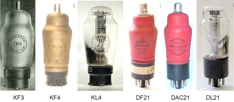
Figure 13. Some representatives from the third and fourth generation of battery tubes.
The tubes from the D21 series were still fabricated on a glass pinch, a technology that was ōborrowedö from the fabrication of incandescent light bulbs. This technology unavoidably resulted in rather large tubes. The demand for smaller tubes for portable equipment resulted within Philips in the development of the ōall-glassö Rimlock envelope. This envelope was used for the successor of the D21 series. This series comprised the DK40 (mixer), DAF40 (diode-RF pentode), DAF41 (diode-LF pentode) and the DL41 (output pentode). These tubes more or less used the same filament as the D21 series, but in the DL41 a novelty was introduced. The filament was split into two halves which made it possible to used only one section (energy savings configuration) of both (maximum output power). However, already during the war an even smaller envelope was developed in the US, the so called ōminiatureö envelope. The further demand for even smaller tubes resulted in the introduction of a further two series of battery tubes in the miniature envelope.
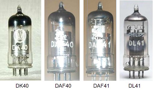
Figure 14. The fifth generation of battery tubes (Rimlock series)
Miniature Battery Tubes for a filament current of 50mA.
The battery tubes series discussed in this section encompasses the following tubes: DK92 (heptode self-oscillating mixer), DF91 (RF pentode), DAF91 (diode ¢ LF pentode), and the DL92 and DL94 output pentodes. The DL92 is primarily designed for anode batteries of 45-67.5V, while the DL94 was designed for 90-150V. These tubes use a nickel filament wire and draw 50mA of current at a filament voltage of 1.4V. Both output tubes have two 50mA filament sections which can be switched in parallel or in series.
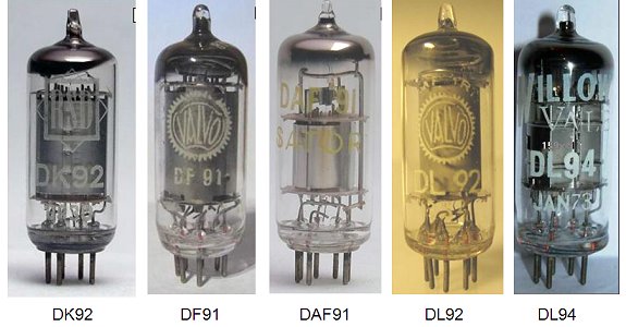
Figure 15. The sixth generation of battery tubes (91/92 miniature series)
The reason that for these tubes again nickel was used instead of tungsten is that the filament of these Miniature tubes was considerably shorter than the filament in the Rimlock series. At the time that these tubes were designed, it was not clear if it would be possible to reliably fabricate tungsten filament wires with the required dimensions. Later is did appear possible, so that tungsten was again used in the D96 series.
When the high voltage battery gets exhausted in portable receivers, its voltage can drop to less than 70% of its nominal value. It is important that the receiver continues to function properly, even for these very low anode voltages. Especially the mixer tube DK92 still performs satisfactorily for the 10m band (30MHz) at an anode voltage as low as 45V.
Miniature Battery Tubes for a filament current of 25mA.
Already in the D20 and corresponding Rimlock series tubes with a filament current as low as 25mA were introduced (e.g. DAC21, DF21, DAF40, DAF41). However, it proved to be impossible at that time to fabricate mixer tubes and output tubes with such a low filament current. These tubes therefore used a 50mA filament. This made it difficult to implement receivers in which the filaments were placed in series. To make this possible, the two 25mA tubes had to be connected in parallel. This meant that if one of the two tubes died due to a broken filament, automatically also the other tube died. This made these tubes rather unpopular. In the DK92, DF91, DAF91, DL92, DL94 series this problem was eliminated by the implementation of 50mA filaments for all the tubes.
In the latest series of battery tubes, the D96 series, all filaments are designed for 25mA, resulting in the lowest power consumption to date.
The series comprises the: DK96 (mixer), DF96 (RF pentode), DAF96 (diode ¢ LF pentode) and the DL96 (output pentode). The output pentode is equipped with two filament sections each 1.4V at 25mA. It is possible to use only one filament at 25mA (lowest power consumption, reduced output power), two filaments in parallel (1.4V at 50mA for normal use) or to use both filaments in series for receiver architectures in which all filaments are connected in series.
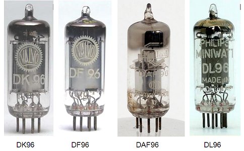
Figure 16. The seventh and last generation of battery tubes (96 miniature series)
In this latest series of battery tubes, tungsten was again used for the filament. Both tungsten as well as nickel have their own specific advantages and disadvantages. Nickel is a metal with a smaller spring-force than tungsten; also the coefficient of thermal expansion is smaller for nickel than for tungsten. For this reason the mechanical tension needed to keep a filament centered in the electrode system is smaller for nickel than for tungsten. Additionally, tungsten expands much more than nickel when it is heated, requiring a much higher tension in the wire to keep it straight. Consequently the nickel filament is pressed with less force against the mica isolators and hence also cools down less as compared to tungsten filaments (the cooling of the filament occurs mainly at the two point where it touches the isolators). In a tube with a short filament, as in these miniature tubes, it requires therefore less power for a nickel wire to reach the proper temperature for emission than for a tungsten wire. This is the main reason why with the transition from Rimlock tubes to miniature tubes nickel was used instead of tungsten.
The problem with the D96 series of tubes was that the current for a single filament had to be reduced to only 25mA. The fabrication of such a filament in a miniature envelope using nickel, would require a wire thickness of only 17um. Nickel is just too soft to make wires that thin! Tungsten is much stronger; in sub-miniature tubes for hearing-aids even wires with a thickness of 8um are used. It was therefore not the thickness of the tungsten wire (11 um) which prevented the fabrication of tungsten filaments for the D96 battery tubes, it was the fact that these tubes should also be suitable for series connection. This required that all filaments use almost exactly the same current, which in turn poses very strict requirements on the variation of filament thickness. Until recently it was not possible to make an 11um thick tungsten wire with the required thickness tolerances. However, recent technological progress as has overcome this barrier, so that the D96 is now a reality.
The higher mechanical tension on the tungsten filament also has an unexpected positive side-effect. Due to the higher tension the mechanical resonance frequency of the wire has shifted from 1000Hz for the D90 series to 4300Hz in the D96 series. This is well into the fall-off regime of the audio response curve of the radio, while 1000Hz lies right in the middle of the flat-part of the curve. The makes the tubes much less sensitive to vibrations or shocks (microphony).Æ
generation
tube
seriesfilament
materialfilament
typeemission
processtotal filament
current radiobase/
envelope
I
A420,A409,B406,
B403W
40um
bariumazide
350mA
B4
II
KK2, KF1, KF2,
KL1, KL2Ni
-
drag coating
-
C7A
III
KF3, KF4, KL4, KL5
W
25um
drag coating
-
P8A (P socket)
IV
KF3, KF4, KL4, KL5
W
25um
drag coating
-
P8A (P socket)
V
DF21, DAC21, DL21
W
10um
cathaphoric Ba coating
150mA
K8A (octal)
VI
DK40, DAF40, DAF41,
DL41W
10um
cathaphoric Ba coating
150mA
rimlock
VII
DK92, DF91, DAF91,
DL92, DL94Ni
-
spray coating
200mA
miniature
VIII
DK96, DF96, DAC96,
DL96W
11um
spray coating
125mA
miniature
| to top of page | back to homepage |