|
Contents:
|
|
|
Contents:
|
|
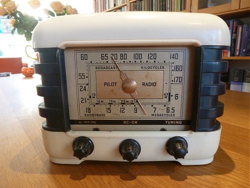
The small Pilot T502 receiver on the top of this page has been a part of my life for at least 45 years. It is the only one of all those tube radios that survived the cleaning rages in the seventies and eighties when these old radio tube radios were considered to be absolutely worthless. The strange thing is, that it got hat special status not because it worked so beautiful – it has not played for as long as I can remember – but probably because it looked so odd or because it became part of the family in such a special way.
I could not have been older than a year or ten (forty years ago) when my father and I visited my uncle Arie, at least I think it was him. I have only a very faint recollection of the visit. The only thing that I remember is that he lived near the “Schieweg” in Rotterdam, and that during that occasion my uncle gave me an old wooden toy boat and my father an old radio. I have a faint recollection of my father working on the radio in the small “serre” behind my parents bedroom trying to get it working, and imagine that I heard it faintly playing on one of those occasions. The next recollection I have of it is years later when we had moved from Rotterdam to Moerdijk. The radio was of American design and intended for 110-120 V mains. Living in Holland, the land of Philips, such a radio was an oddity. I remember that I was surprised by the odd shape and type numbers of the tubes, which are completely different from the European style of design. My uncle Arie has always been a sailor, and most likely he took the radio with him from the States directly after the war.
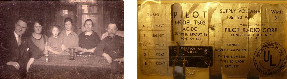
Figure 1.1 Left, one of the very few photographs I have of my uncle Arie (man on the left) taken in his elderly house around 1920.
Right, label on the bottom of my T502.
I had completely forgotten all about the radio, until by mother moved out of the house in Moerdijk where we had lived for such a long time. I took the radio with me, and it has been a kind of living room ornament ever since. I once tried it, but apart from some crackling it didn’t make any sound. Also in our house it became one of those things that you see every day but never notice. Until we added a part to the house some years ago and the whole living room had to be cleared. On the bottom of the radio I found a label with both the manufacturers name and the model number: a Pilot model T502. Since the last time I had looked at the radio, indternet had been invented and I was now able to download a circuit diagram of the radio within ten minutes. Searching the web I also learned that the T502 was what is called “An American Fice (AA5).” In short, reason enough to restore it to its old glory and to do some research. It took a few year due to all kinds of dramatic family events, but now the moment is there.
| to top of page | back to homepage |
Isidor Goldberg was born in Manhattan, New York, in 1893. His parents immigrated from Vienna in 1878. When he was about four years old, Isidor's mother died leaving his impoverished father to support the boy and his two infant sisters in the East Side of New York. Isidor was taken in and raised at the Hebrew Sheltering Guardian Orphan Asylum in New York. He graduated from Hebrew Technical Institute in Mechanical Arts in 1908.
From 1910-1914, Goldberg was a test pilot for Curtiss Aeroplane and Motor Corporation or Curtiss Airways. Afterwards he sold aeronautical supplies and model airplanes. In 1915 Goldberg was granted a U.S. patent for his invention of an emergency lamp.
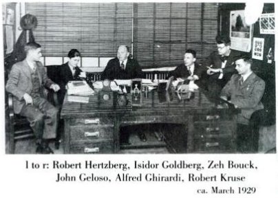 In 1919, Goldberg founded Pilot Electric Manufacturing Co. in 323 Berry Street, Brooklyn, New York, to manufacture parts and kits for home radios. Robert Hertzberg, editor of Pilot’s house organ Radio Design: “Pilot was one of the very few real fabricators of the radio industry. In a crowded factory in Brooklyn, NY, it made its own tools and dies and manufactured all the bits and pieces of its components and assemblies. It did all its own turning, stamping, winding, plating, forming, etc. Automatic screw machines and power presses competed competed for floor space with Bakelite molders, spray booths, etc.”
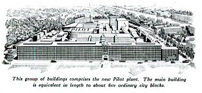
With the Brooklyn factory taxed to capacity, the management was hunting for new facilities even before October 1929. They soon found a cluster of huge buildings, a former cotton mill, in Lawrence Massachusetts. Practically the entire engineering staff and administrative personnel along with the production workers, moved up willingly because their
salaries were high and jobs in other firms were scarce. Again the
of the company was changed to Pilot Radio and Tube Corp. and, as of 1932, to Pilot Radio Corp. Unfortunately, the interruption of production and continuity proved dissaterous. After a particularly bitter winter over 1931-1932 the whole operation collapsed over a short time. Goldberg himself returned to New York and organized a new firm also called Pilot.
 In the late 1940s and early 1950s plants were built in Britain (prior to World War II), South Africa (by 1953), and Israel (in 1947). All three plants were sold in 1959. Goldberg was president of the company from its inception until his death in 1961.
Goldberg, as president of Pilot Radio Corp., was a leader in developing and introducing new products and new uses for communications equipment. The company was the first to introduce a civilian short wave radio (WASP, 1925) and a battery-powered, portable radio (1937). In 1930 Goldberg pioneered in the development of long distance ground-to-air communications with his "flying laboratory". In 1937 Pilot introduced the first "popular-priced" FM tuner (Pilotuner). The first real breakthrough in television technology was made by Pilot engineers in 1928. The next year, Pilot sponsored the first scheduled TV broadcasting and offered TV receiver kits for sale. By 1937 the company was producing ready-made TVs. Ten years later Pilot marketed the first miniature (portable) TV receiver (Candid TV).
During World War II, Pilot Radio Corp. produced communications equipment for the war effort and in 1945 won the prestigious Army Navy "E" Award for excellence in production of war equipment. The Signal Corps stationed an inspection team at the plant from 1942-1945 to help the firm convert from civilian to war-time production. Even as late as 1949, 80% of the company's output was sent to the U.S. Government. The New York factory also supplied communications equipment to the Soviet and Chinese governments during the war. Representatives of those two countries visited the Pilot factory between 1941 and 1945. The British plant, Pilot Radio, Ltd., headed by Goldberg's partner, Harry Levy, produced war equipment for the British government during the war. The U.S. Office of War Information required Goldberg to begin a record manufacturing plant to produce sound recordings designed to build the morale of the armed forces. After the war, Goldberg experimented with manufacturing civilian recordings, but found the record industry too demanding and discontinued production in 1949.
By 1947 Goldberg began to replace war production with the manufacture of televisions. In 1950 he joined other television manufacturers in protesting a proposal of the Federal Communications Commission (FCC) to assign the color television system developed by Columbia Broadcasting System (CBS) as the system standard. Goldberg argued that the CBS color system was still experimental and the FCC was trying to impose impossible deadlines on the rest of the industry. By 1953 Pilot had added production of high fidelity (Hi-Fi) radio/phonograph/television sets and components.
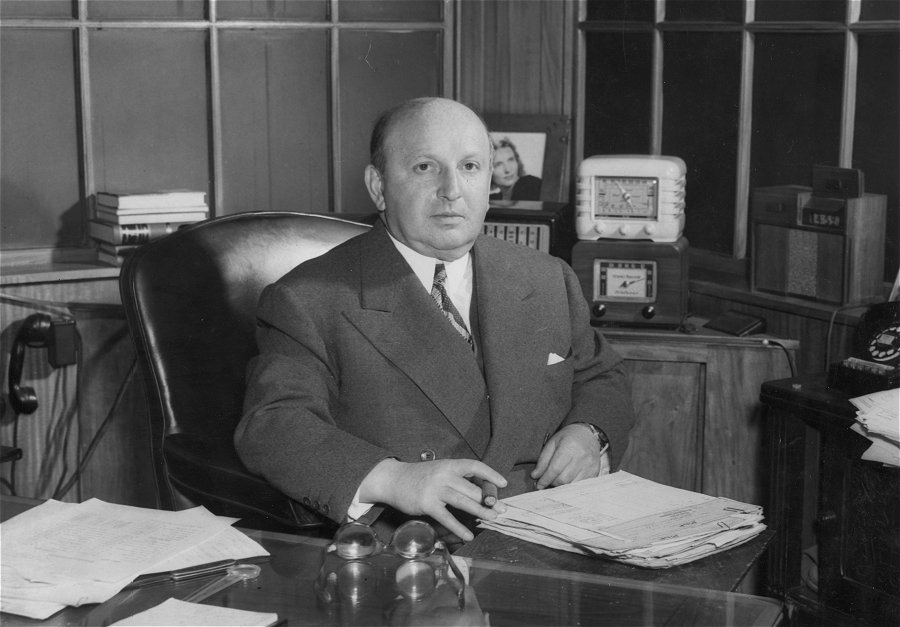
Figure 2.1 Isidor Goldberg around 1947, note the T500 behind him. Photograph: Americal Jewish Archives.
In addition to his activities as an inventor and innovative businessman, Goldberg was an ardent Zionist and philanthropist. He was a co-founder of the United Jewish Appeal in the United States and a member of the Zionist Organization of America. He established a subsidiary of his company in Tel Aviv in 1947. And he supplied communications equipment to the new Israeli army in 1949. In 1923 and 1934 Goldberg helped Technion - Israel Institute of Technology to acquire land in Haifa. He supported Technion with funds for research scholarships because he realized the value of a technological education. Five years after Goldberg's death his widow established the Isidor Goldberg Electronics Centre at Technion in his memory. A Chair was named in Mrs. Joan Goldberg Arbuse's honor in 1973 and she received an honorary doctorate from the university in 1987.
For many years, Goldberg maintained ties with the orphanage in which he was raised. He served on the Board of Trustees for 33 years, until his death in 1961. In 1928 he was elected to the Board of Hebrew Sheltering Guardian Society (HSGS). In 1940 he was a founding trustee of the Jewish Child Care Association, formed by the merger of the HSGS with two other New York child care organizations. In 1914 Goldberg bought a chicken farm on Staten Island and sold eggs as a sideline to selling wireless parts. When his electronics business expanded he sold the farm, but in 1925 he purchased a 325-acre dairy farm in Westchester County. By day he ran his electronics factory and evenings he worked on his farm. Isidor Goldberg had 3 children by his first wife, Rose Goldberg Lenitz. In 1936, Goldberg married his second wife, Joan, the daughter of a Jewish father and Quaker mother. Isidor Goldberg died in 1961 at the age of 68.
| to top of page | back to homepage |
This situation changed in the thirties. First of all radio became extremely popular and as a result the number of radio stations increased explosively. With all these radio stations crowding the ether, radio sets required a better selectivity than that could be obtained with a TRF architecture. Secondly, there was a demand for lighter radios which could be carried from one room to the other. This meant that it was necessary to get
 rid of the heavy lead-acid and high voltage batteries, which were a nuisance anyway. The obvious solution was to use a transformer to power the filaments. With directly heated filaments this was very difficult because the alternating voltage introduced a significant amount of hum in the circuit. Eventually this resulted in the development of indirectly heated cathodes in which the heater and the cathode where de-coupled. Finally, the crisis of the thirties called for cheaper radios. Mass production and a standardization of circuits and components was the obvious solution here.
The advantages of heterodyne receivers over TRF sets are so obvious, that in retrospect one wonders why this architecture was not endorsed much earlier. Many subtle factors play a role here, which are not easily put into a logical or chronological order. What is certain is that the improvements in tube technology played an important role. Modern tubes offered a better performance combined with a better reproducibility, a prerequisite for mass production. Additionally, the drive for lower cost motivated manufacturers to developed tubes which offered two or more functions in one glass envelope. Most obvious are the heptodes or pentagrid frequency converter tubes which offered in one tube the functions of: RF amplification, LO oscillator and frequency mixing. Early thirties RCA introduced the 2A7. It was the first indirectly heated heptode/pentagrid frequency converter tube. Together with a 58 remote cut-off pentode as IF amplifier, a 55 double-triode detector first audio amplifier, a 59 audio output and an 80 rectifier it made a 5 tube radio. In its concept, these 5 tube sets may be called prototypes of the true AA5. However, these sets still contained a power transformer, and a heavy one too! The filament voltage of these line-ups was 2.5 V and connected in parallel they loaded the transformer with a staggering 8.5 Amps!
The power transformer happened to be one of the most expensive parts of a radio. For the high anode voltage a transformer was not really needed. By rectifying the mains voltage a suitable anode voltage could easily be obtained. The problem was the low voltage supply for the filaments. Here again the indirectly heated cathodes offered the solution. For indirectly heated cathodes, the filament is isolated from the cathode. The filament can thus be at a completely different potential than the cathode. This made it possible to connect all the filaments in series so that the total voltage equals the mains voltage (see also next section). This simple trick completely eliminated the power transformer, paving the way for low-cost mass produced radios. It came however at a price, the elimination of the power transformer meant that the whole circuit, including sometimes the chassis was connected to the mains, and that in principle touching any metal part could be lethal! Without a power transformer, it was also possible to operate these radios from a DC power supply. That is why the AA5 is sometimes also known as the “AC/DC set.”
By the mid thirties, the five tube radio had become the standard. Some sets had a tube less, but also performed considerably less, while some luxurious sets had six tubes, but for the average receiver five tubes was optimal. Set makers had also figured out the most economical way to connect all the heaters in series so that they could be fed directly from the mains: the All American Five (AA5) was born. A further optimization of the AA5 circuit and squeezing for costs resulted in an almost identical circuit diagram for all AA5s, while also the set of tubes, called a line-up, was standardized: 12SA7 frequency converter, 12SK7 IF amplifier, 12SQ7 detector + LF amplifier, 50L6 Power Output and, 35Z5 Rectifier. Manufacturers went to the extreme to reduce costs, as Max Robinson puts it in his fantastic circuit review of the AA5: “The marvel is how well they work considering their construction. There's no such thing as a wiring harness. Wires go every which way, crossing over, twisted around, power next to audio, audio next to RF, power next to RF. Terminal strips are seldom used or used in great moderation. That sometimes means that wires are just brought together in the middle of the air and soldered together. Yet still they keep on ticken. The design has been so well refined that it seems impossible to build one that won't work.”
The design of the AA5 didn’t change much for the next decades. After the war the octal tubes were successively replaced by modern miniature (noval) tubes which had been developed during the war, typically the: 12BE6, 12BA6, 12AV6, 50C5 and the 35W4. Just as for the octal tubes, the filament current for these miniature tubes was still 150 mA. Also in many cases the simple loop antenna was replaced by a ferrite core antenna. In the early sixties, the 150 mA AA5 line-up was replaced by a 100 mA heater string line-up consisting of the: 18FX6, 18FW6, 18FY6, 32ET5/34GD5 and the 36AM3. Since the heater of the output power tube operated on a lower power level, also the output power was less, and the tubes took more time to heat up. Finally, in the sixties the AA5 was replaced by, what Max Robinson coins, the AJ6, the All Japanese Six transistor radio.
| to top of page | back to homepage |
The primary motive for developing indirectly heated cathodes was to replace the DC lead-acid battery by a transformer (Fig. A). For users this already meant an enormous improvement in comfort of operation. Around 1934 RCA introduced a brand new line-up of indirectly heated tubes consisting of the: 6A7, 6D6, 75, 6F7 (converter, IF, diode-triode, pentode-triode) which all operated on a heater voltage of 6.3 V so that they could be directly fed from a 3-cell lead-acid car battery. At the same time these tubes used a moderate heater current of 300 mA. The fact that these tubes use the same heater current made it possible to connect the heaters in series. To realize a complete receiver with all the heaters connected in series, th line-up only needed to be complemented with an audio power amplifier and a rectifier. These tubes operate on a higher power level, so that a 6.3 V / 300 mA heater was insufficient. Since for a series connection of the heaters the current was already set by the frontend line-up to 300 mA, the only way to increase the heater power was to increase the heater voltage. As it happened this was no problem at all because the sum of all the heater voltages had to equal the mains voltage of 110 V anyway. In this way tubes like the 25L6 (power audio) and the 25Z5 (rectifier) were developed. The sum of the heater voltages still didn’t equal the main voltage (6+6+6+25+25 = 68 V) so that the missing 50 V or so was dissipated in a resistor, resistive power chord or a special ballast tube like the L49BG (Fig. B).
Because of their low price, the transformer less sets became increasingly popular, but the ballast resistor was of course a nuisance. It costed a lot of power, and generated a lot of heat. The prospect of even higher sales motivated tube manufacturers to develop a new line-up which would eliminate the need for a ballast resistor. By halving the heater current to 150 mA, the voltages of the heaters could be about doubled. With a bit of squeezing on the rectifier side this resulted in what we now know as the classical AA5 line-up: 12SA7, 12SK7 , 12SQ7, 50L6, 35Z5, adding up to a total voltage of 121 V, just about the mains voltage (Fig. C).
There was one small problem left: the small pilot light that lights the dial; where to put it? At first sight the simplest solution might seem to take a 6 V / 150 mA lamp, and just insert it in series with the heater string, the small additional voltage drop wouldn’t pose such a big problem (Fig. D). Unfortunately this doesn’t work. To understand why, one has to realize that the resistance of a cold filament can be almost a factor ten lower than the resistance at the operating temperature. This not only applies to the heaters of the tubes, but also to the filament of the pilot lamp. The heat capacity of the filament of the lamp is however much smaller than the heat capacity of the heaters. As a result the filament of the lamp will heat up in a fraction of a second, while the heaters of the tubes will take about half a minute to heat up. During those first seconds, when the heaters of the tubes is still low, almost the complete line voltage will drop over the small pilot lamp causing it
to burn through in a flash.
A solution was found by providing a tap on the heater of the rectifier at about 7 V. The voltage drop over that part of the heater can simply be used to power the pilot light (Fig. E). Unfortunately this simple trick doesn’t work as simple as that. The pilot light of course also takes it’s share of the current through the heater string, so the part of the heater of the rectifier that is shunted by the pilot light is operating at a lower current level meaning that part of the filament will be under-heated. The engineers in the thirties found a very elegant and simple solution: by cleverly connecting the high voltage rectifier circuit to the heater ring, the high voltage current neatly compensates for the current though the pilot light (Fig. F). This trick became the standard for the AA5.
It also explains the rather mysterious behavior of the pilot lamp after the set is switched on. Directly after the set is switched on, the current though the cold heaters will be in the order of one or perhaps even two Amps, while the anode current will be zero. The current though the pilot lamp will be so small compared to the current through the heaters that the voltage drop over the heater will completely determine the pilot lamp voltage so that it will run at its nominal voltage. When the heaters heat-up, their resistance will increase and the current through the heaters will decrease. At a certain point the current through the heaters becomes comparable to the current through the pilot lamp, so that the current will be more or less equally shared between the pilot lamp and the tapped section of the rectifier, causing the pilot lamp to dim. A few seconds later the high voltage part will start to draw current which is added to the heater / pilot lamp combination causing the light to burn at its normal intensity.
| to top of page | back to homepage |
|
|
|
|
Figure 5.1 Click on one of the pictures to download the high resolution scan.
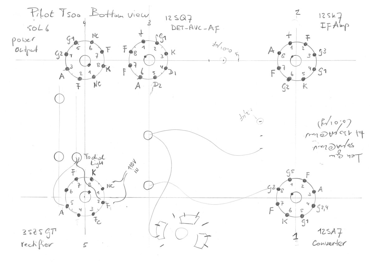
Click here for a bottom view sketch of the tube connections.
The circuit diagram of the T502 is a nice example of an AA5. Max Robinson has written on his site “Fun with Tubes” what I think is the best and most accessible circuit description of the AA5. It comes in 6 chapters:
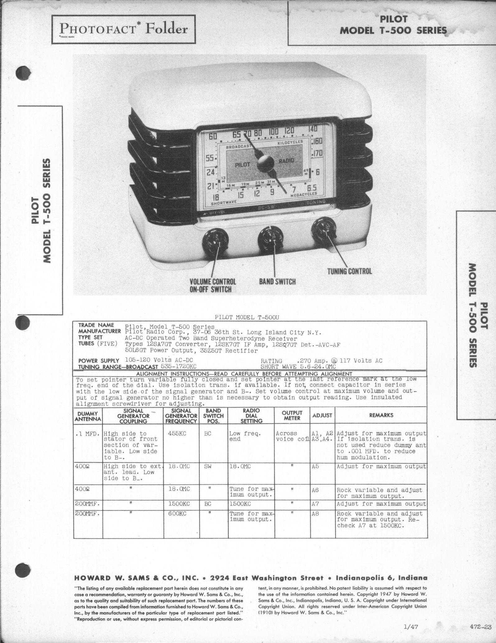
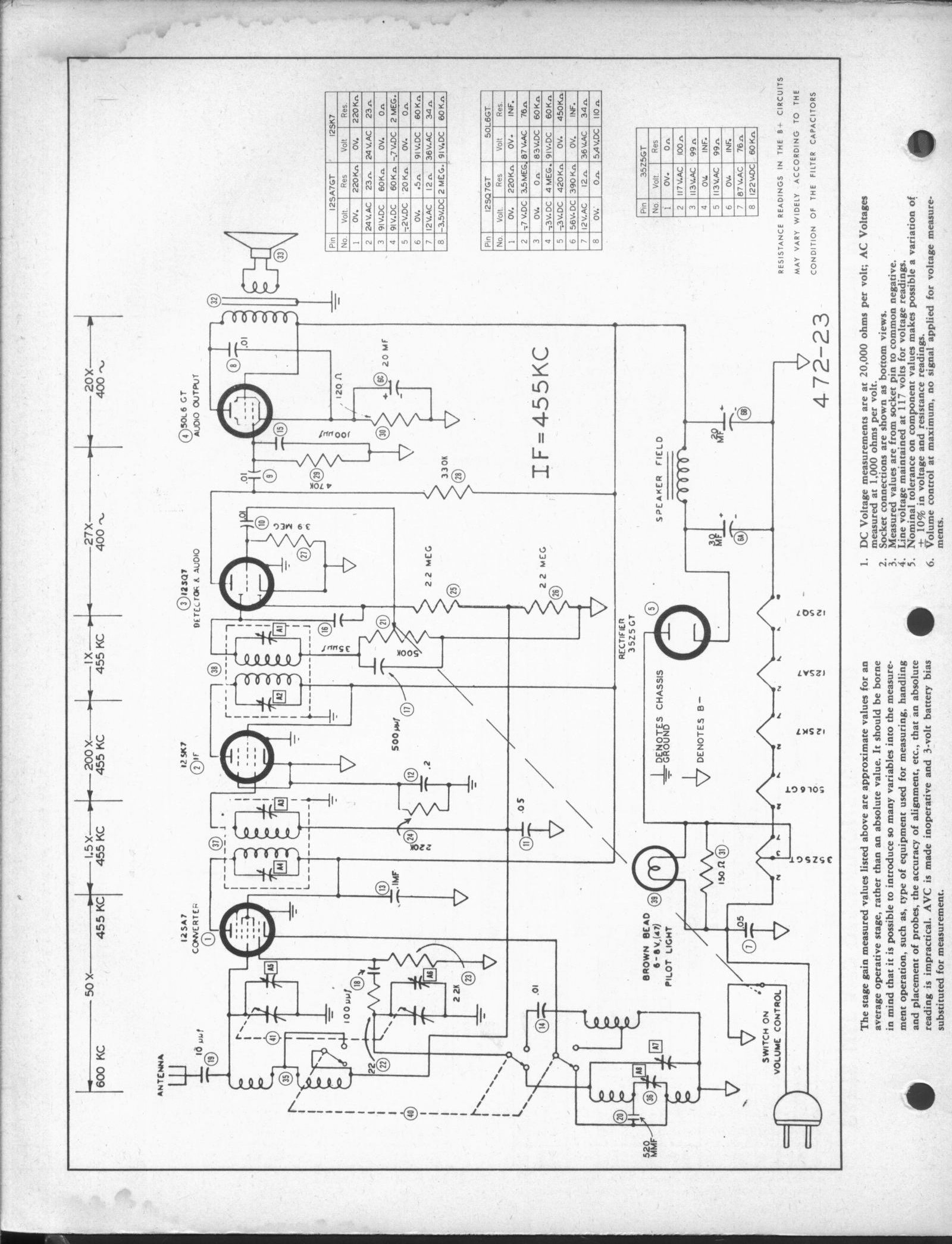
Figure 5.2 The circuit diagram of the T502 is pretty representative for all AA5s.
The only additional things worth mentioning here are that the T502 is a dual band set, covering both the broadcast band (535-1720 kHz) as well as the shortwave band (5.6 – 24.0 MHz). That is probably also the reason why this set doesn’t have a built-in loop antenna as most AA5s have. Instead there is a wire at the backside for connection to a normal wire aerial. Some AA5’s use a resistor in the hum filter of the high voltage rectifier. In the T502 the electromagnet of the loudspeaker doubles as an inductor for this purpose. That is about it, for the rest everything is pretty much as it should be.
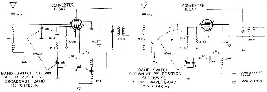
Figure 5.3 The RF circuit depending on the position of the band-switch.
| to top of page | back to homepage |
The past one and a half years almost all my spare time has been spent on the uTracer project: a small and versatile tube-tester / tube-curve-tracer. When it was finished I tested a whole range of tubes to see how well it functioned. One set of tunes I tested was the AA5 line-up from the Pilot T502. In fact the curves below were measured long before the restoration work on the T502 started.
Figure 6.1 12SK7 Remote cut-off IF Amplifier
Figure 6.2 35L6GT Beam AF Pentode. An external power supply was used for the filament.
The 12SK7 remote cut-off Amplifier tested out to be pretty ok (Fig. 6.1). Perhaps a little bit lower emission than it should have, but no reason for concern. The same applied to the 35L6 audio power output (Fig. 6.2). This tube obviously is not original. I suspect that at so moment my father must have substituted it in the absence of a 50L6 (see next section). The 35L6 was tested using an external power supply for the heater since the uTracer doesn’t support heater voltages higher than 19 V.
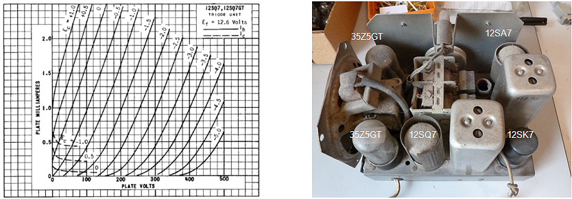
Figure 6.3 12SQ7 Double-diode triode, audio pre-amplifier and detector
After some testing the culprit was quickly found: a nearly dead 12SQ7 audio pre-amplifier/detector (Fig. 6.3). For a moment I thought I was lucky because I found another 12SQ7 in my collection, but that one also had a very poor emission. In other words, the search had started for a “new” 12SQ7 to get my set playing again.

Figure 6.4 35Z5GT high voltage rectifiers. An external power supply was used for the filament.
The 35Z5 high voltage rectifier was also pretty ok (Fig. 6.4). Also this tube was tested with an external heater supply.
Figure 6.5 12SA7 RF mixer/oscillator.
Decent testing of the 12SA7 hexode (“pentagrid”) frequency changer tube was a bit less straightforward. Philips e.g. publishes DC curves of their hexodes, but these were not available for the 12SA7. However, probably for testing purposes, the datasheet states some DC characteristics of the tube in “non oscillating” mode. With the anode and screens connected to 100 V, and the grids to 0 V, the cathode current should be around 25 mA (I assumed that the suppressor grid was kept floating). Figure 21 shows a set of Ia(Va) curves of the 12SA7 tested in this configuration whereby the anode voltage was varied between 0 and 100 V, and the first control grid voltage was stepped from -7 to 0 V. The very last point measured corresponds to the point mentioned in the datasheet, and the anode very nicely matches the current specified in the datasheet (25 mA).
| to top of page | back to homepage |
When I started work on the T502 it was in pretty bad condition. It hadn’t played for as long as I could remember, and the backside was missing so that it had been gathering grease and dust in our living room for almost two decades. The only good thing was that at least it had been stored in a reasonably warm and dry environment. Actually the whole restauration of the T502 started a year ago when I was anxious to test my uTracer tube-tester on the AA5 line up of the T502. To my surprise four out of five tubes were perfectly ok, while only the 12SQ7, detector and audio pre-amp, was dead. Surprisingly (because I do not have that much American tubes) I had another one lying around, but that one was also dead. Fortunately, Cor Moerman of Musem “Jan Corver,” the Dutch museum of Radio Amateurs had one lying around, and he is always happy to get rid of “old stuff” when it can find a new and warm home! The 12SQ7 was made by Philips (!), brand new, and in the original box. He also had an 50L6 power output tube so that I could restore my set to its original state. It nevertheless took me almost a year to get started on the restauration because the work on the uTracer kit took me much more time than expected.
At this point, perhaps superfluously, I would like to warn the readers of this page that they should keep in mind that, since these sets are directly connected to the mains, touching of any metal part, including the chassis, can be lethal! Only work on these sets when they are connected to the mains via an isolation transformer! I have by now some experience in restoring vintage equipment, but it is always interesting to learn more tricks from the real experts. I came across the book “The Vacuum Tube Shortwave Radio: Understanding and Troubleshooting” by Richard McWhorther. It is a great resource of information but you will need a password to open the pdf file (password = “allamericanfiveradio”). Also the powerpoint presentation “How to restore your tube radio” by Paul Pinyot is very informative. Finally, for the Dutch speaking people I would like to recommend the “Tips and Trick page” of the Dutch vintage radio forum.
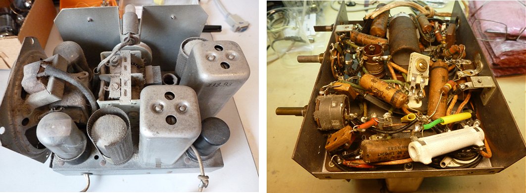
Figure 7.1 Thirty years of dust (left), interior of the chassis after opening (right) The big white resistor was added by my father to make up for the lower heater voltage of the 35L6 he used to replace the 50L6.
The first thing was of course to remove the chassis from its very nice Art Deco Bakelite casing. That was easy enough. Just remove the knobs, two screws and the chassis slides out. In contrast to most cheap AA5 type sets, the bottom of the chassis was closed by a solid metal lid, so that the complete interior is shielded. Probably this was done because of the additional shortwave band. The result was of course that the bottom side of the chassis was relatively clean and dust free. Especially the tuning capacitor was very dirty and dusty. The paper of the loudspeaker was torn at several places while apparently also somebody had been messing around with its wires. The pilot lamp was loose in its socket because it was replaced by a European “threaded type,” while the socket was intended for a bayonet socket. The first thing was to remove all excess dust with the vacuum cleaner and a soft brush. Next, the outside of the chassis was thoroughly cleaned with cotton-tips and isopropyl alcohol. Fortunately, I have a large collection of light bulbs which contained the specified 6 V / 150 mA pilot lamp with bayonet socket
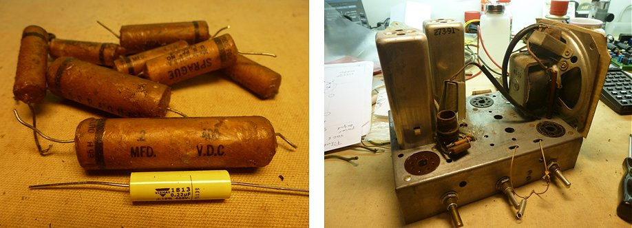
Figure 7.2 The replaced paper/wax capacitors (left). The modern 0.2 uF / 400 V is a replacement for the big paper/wax capacitor directly behind it! Right, chassis with tuning capacitor removed
The interior of the chassis showed clear signs of previous repair work, probably done by my father. The mains chord was obviously not original and in bad condition. At some moment in time, my father must have replaced a defect 50L6 with a 35L6. To make up for the difference in voltage, he had inserted a 100 ohm resistor in the heater chain. Luckily the 35L6 also uses a heater current of 150mA, and 150 mA times 100 ohm exactly makes up the missing 15 V. Since I had a “new” 50L6, I decided to bring the set to its original state by removing the resistor. Just for my own convenience, I made a bottom view sketch of the chassis to facilitate future electrical measurements. More serious was the fact that the large ceramic double trim capacitor, which is used in the LO-oscillator for the broadcast band, was broken. It was probably also my father who had repaired it with a replacement trimmer. For the moment I decided to leave the situation as I found it.
The circuit contained quite a number of paper/wax capacitors. These capacitors look particularly greasy and dirty and they are almost always leaky. One of the first things done was to replace them by modern axial polyester (PET) capacitors from Vishay Roederstein (e.g. Farnell 1166856). After removal I checked the paper/wax capacitors, and on average they showed a leakage current of 50 uA to 150 uA at 200 V. The difference in size of modern capacitors compared to the old paper/wax types is enormous so that the recapping created a lot of welcome space in the interior of the chassis.
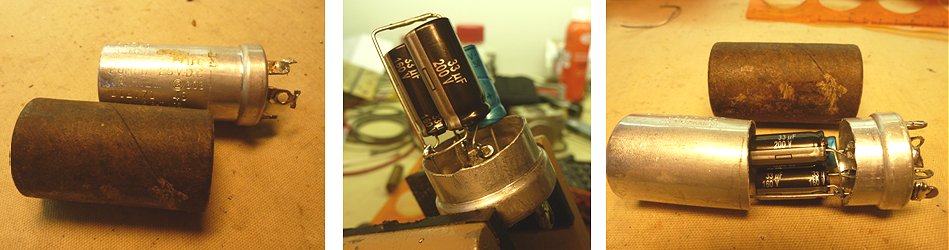
Figure 7.3 Refitting of the electrolytic capacitor(s).
The variable tuning capacitor was especially dirty and greasy so that I removed it from the chassis and cleaned it in alcohol in an ultrasonic bath. It didn’t completely clean it, but it greatly improved. I know that some people recommend cleaning these capacitors in the dishwasher, but I didn’t dare to do that! Also the trimmer capacitors on top of the tuning capacitor showed some signs of creative restoration work and for the moment I left them untouched.
In most of these old sets the high voltage electrolytic filter capacitors are in a bad condition, usually beyond repair. These old capacitor cans usually offer enough space to accommodate one or more modern electrolytic capacitors. I therefore usually prefer to just remove the old contents from the capacitor and fill it up with new capacitors. In this case that was very easy because the metal can of the capacitor was shifted in an isolating cardboard tube. After removal of the cardboard tube, the capacitor was opened with a metal saw and the interior was removed, and the inside of the metal can was cleaned. In this case the tube contained no less than three capacitors: two 20 uF / 150 V filter capacitors and one 20 uF / 25 V decoupling capacitor for the cathode resistor of the 50L6. The replacement capacitors look tiny compared to the old one.
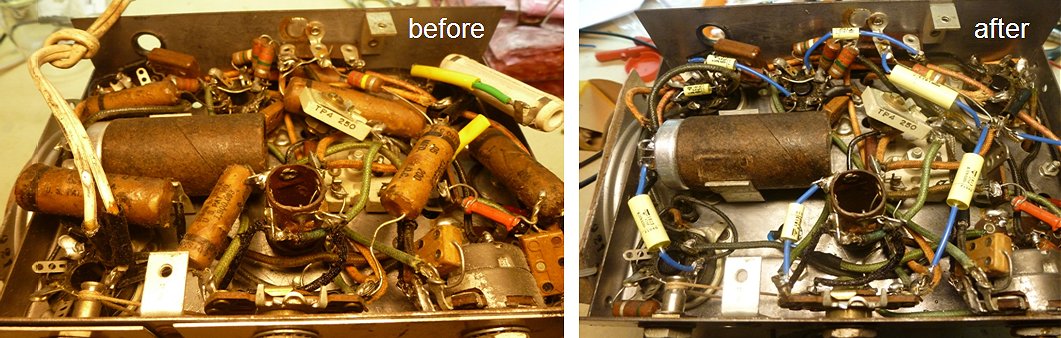
Figure 7.4 Interior of the chassis before and after recapping.
Finally, the set was switched on using an isolation transformer and a variac. The pilot lamp behaved as exactly as it should, a good sign. At first the set didn’t make a sound at all. The problem was a broken connection inside the Bakelite tube socket of the 50L6 power output, what
 a shame. By manipulating the tube a bit, a stable audio output was achieved, but I have to find a replacement later on.
It always surprises me how much interference digital equipment generates on the AM broadcast band. Most of my equipments is at least partially digital, and even in standby generates interference. The equipment on my workbench is switched on/off by one central switch, and when it is on, virtually no reception in the broadcast band is possible, even though most equipment is off or in standby! At first the reception was a little disappointing. An audio fragment can be heard by clicking on the icon to the left. One or two weak (chinese) stations and for the rest a lot of whistling and a noise what is by some people described as “motor-boating.” Clearly the IF section needed aligning.
Fortunately my HP8601A RF generator is still completely analog, so that one was used to align the IF filters. Again the book of Richard
McWhorther (see above or refs) gives a good explanation of how the IF can be aligned. Also in the very first number of Popular Electronics (October 1954) there is a very useful and amusing article
on radio alignment (I have to find the original of that transcription one day). First the second IF filter was aligned by applying a 455 kHz signal modulated with a 1 kHz tone via a 10 nF / 400 V capacitor to the grid of the IF amplifier 12SK7 (V2). Filter 38 was tuned to maximum signal. Next the 455 kHz signal was applied to the input grid of the Converter 12SA7 (grid 3 of V1). The local oscillator was stopped by connecting grid 1 to ground. In this way IF filter 37 was tuned to maximum signal. After this short and simple alignment, many more stations were found and the whistling and motor-boating was gone. The set also turned out to be reasonably “in the band”, so that given the state of those tuning capacitors those were left as it was. The second audio fragment gives an idea of the T502 after alignment. The sound still isn’t brilliant, but again given the rather fragile state of some of the wiring and the mechanical construction of the IF filters, I decided to leave things as is. It is already great that the set is alive again, and I have no plans
to listen to it on a regular base anyway.
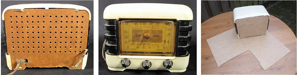
Figure 7.5 Two photographs of another T502 found on Ebay (left). My replacement back cover (right).
Missing on my T502 for as long as I can remember are the back cover and the transparent cover of the frequency dial. Fortunately I was able to trace some pictures of another intact T502 on Ebay (Fig. 7.5). It appears that the original backside was made of hardboard (HDF). Using to some surplus hardboard from an IKEA flat-pack, and my good old fretsaw a new back cover was easily made. I still have to drill the holes, but I have to get a good sharp woodworking drill bit first. Finding a replacement for the transparent front side dial cover will be more difficult. I will leave it open for the moment, I do not intend to run the T502 without an isolating transformer anyway.
| to top of page | back to homepage |
| to top of page | back to homepage |
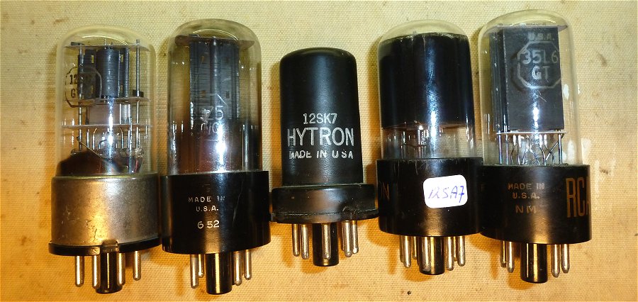
The classical AA5 Line-up (L2R): 12SQ7, 35Z5, 12SK7, 12SA7, and 35L6