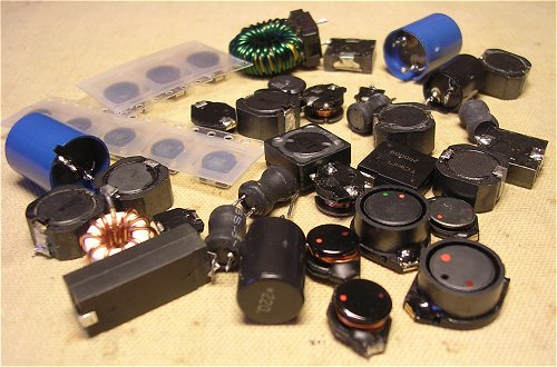
Whenever I can I always salvage (power) inductors from old PCBs and switched mode power supplies. A good assortment of different value inductors always comes in handy during experiments, especially with boost converters and the like. Now, I am sure that there must be a system by which manufacturers of these inductors mark them with the inductance value, but so far I have not been able to discover it. Some inductors have some numbers printed on them, while others are marked with colored dots which are a disaster anyway because I am color blind. To quickly sort out the inductance value of these inductors I use a simple method which I am sure will interest other inductor ignorami. The tools you need are a 0-100 kHz function generator WITH 50 OHM OUTPUT, and an oscilloscope.
Since most people will be more interested in the method rather than in the theory behind it, let’s start with a step-by-step description:
Connect the 50 ohm output of the function generator to the oscilloscope, and select a sine-wave signal.
Adjust the frequency of the generator to approximately 20 kHz.
Adjust the output voltage of the generator to 1 V peak-peak.
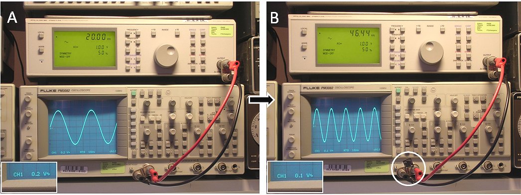
Connect the unknown inductor parallel to the oscilloscope (Fig. 2.1). Doing so will decrease the amplitude of the signal.
Now adjust only the frequency of the generator in such a way that the amplitude on the oscilloscope is exactly half the original value (0.5V pp).
The way I execute steps 3 to 5 is as follows: In step 3 I first set the vertical sensitivity of the scope to 0.2 V/div. Then I adjust the amplitude of the signal generator so that the sine wave exactly fits between the 25% and 75% markings on the screen (Fig. 2.1A). The amplitude is now exactly 1V. Next I connect the inductor (step 4), and increase the vertical sensitivity to 0.1 V/div. In step 5 I now adjust the frequency so that the sine wave again exactly fits in between the 25% and 75% markings (Fig. 2.1B). The amplitude of the sine wave is now 0.5 V.
Finally, read out the frequency, and calculate the inductance from L=4.57/f. With L in Henry and f in Hz. You may also prefer L=4570/f with L in uH and f in kHz.
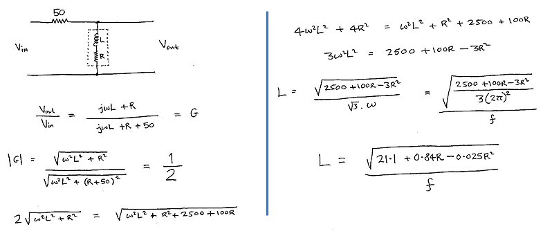
The inductor, in combination with the internal series resistance in the generator form a voltage divider circuit (Fig. 3.1). Without the inductor connected, the voltage drop over the 50 ohm resistor is negligible and the oscilloscope displays the “internal” voltage of the generator. With the inductor connected, the current through the inductor will cause a voltage drop over the 50 ohm resistor causing the amplitude of the signal on the screen of the scope to drop. The current through the inductor is a function of both the frequency as well as the inductance. For a DC signals (0 Hz) the inductor represents a short circuit. For very high frequencies to current through the inductor is negligible. Furthermore, for a given frequency, the higher the inductance, the lower the current.
Figure 3.1 The “circuit diagram”
The exact ratio between the internal generator voltage and the voltage measured by the scope can be calculated with a bit of straightforward network theory:
In this formula L represent the inductance, R the resistance (50 ohm), and omega the radial frequency ( = 2*pi*f with f in Hz). The question now is for what frequency (Vscope/Vgen) = 0.5:
So finally:
In which L is the inductance in Henry, and f the frequency in Hz.
This method only works well for inductors with a low series resistance, and an inductance in the range of say 10 to several hundreds of uH.
The nice thing about a website is that people from time to time make very useful contributions. Karen Orton (UK) improved the method proposed above for inductors which have a significant resistance. Simply DC measure the resistance first and use it in the formula below. Otherwise the procedure is exactly as described above.