
Most (vintage) tube testers perform nothing more than a simple go-no-go test. In most cases they only provide information about the emission of the cathode. Usually the tube is measured as a diode by connecting all the grids and the anode together, and connecting them to a positive bias with respect to the cathode. The cathode current is then some measure of the capability of the cathode to emit electrons.
More advanced and expensive types also measure the transconductance (a measure for the gain). In this case realistic voltages are applied to the grid(s) and the anode, and a small AC voltage with a fixed amplitude is super-imposed on the control grid. The ratio of the amplitude of the resultant AC anode current to the amplitude of the AC grid voltage is then, by definition, equal to the transconductance.
The uTracer is much more than a simple tube tester; it is also a curve-tracer. It measures both the anode as well as the screen currents for a range of specified bias conditions, and arranges the measurements in meaningful sets of curves. From these curves parameters like the transconductance or the output resistance can then be extracted and plotted as a function of bias. Alternatively the uTracer can be used as a tester which extracts important parameters like Ia, Rp, gm and um in your favorite bias point in a matter of seconds.
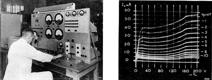
This very early tube curve-tracer was designed and build at the tube development lab of Philips in Holland during the period 1949-1951. Read more about this remarkable machine here.
Already from the very early days of radio tube development, people have been thinking of ways to automatically measure tube characteristics. On the Tracer V2 blog page I have written a small section about the development of automated curve tracing equipment at Philips. I am sure other companies must have developed similar equipment.
The Tektronix 570 was one of the first commercially available curve tracers. It was a huge and very expensive piece of equipment intended for professional use. Professional vacuum tube curve-tracers were never produced in the post tube area. Nevertheless, there are from time to time retro-electronics enthusiasts who dare to undertake the venture of building one themselves. That is not a small matter! It usually requires a set of “heavy duty” power supplies to begin with. Especially the high voltage supplies pose a problem. A typical high voltage supply range is 0-400 V, while the supply should be able to deliver at least 200 mA. This means a programmable voltage supply of at least 80 W, and if you want to test pentodes, you need two of those! Inevitable this means large transformers, heat-sinks and fans. Some of these projects end without ever being completed, others are executed to perfection. An example of the last category is the “RoeTest” from Helmut Weigl.
Helmut himself calls it “the Ferrari” amongst tube curve-tracers. However, for most hobbyists it is probably too complex and/or too expensive.
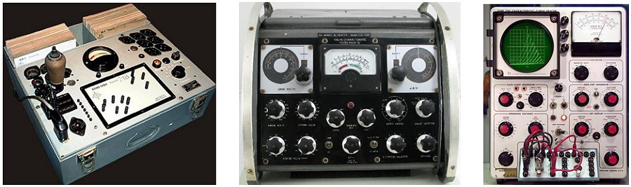
From left to right: the Neuberger RP270/1, a “no-nonsense” tube tester, which is special to me because it is the very first tube tester I ever saw. It was located in the radio shop “van den Embden” in Rotterdam where my father and I would go to test the tubes of our television. In the center an AVO mark IV a tube tester which can also measure the gm. It is by many considered to be the Rolls-Royce among tube testers. On the right, the Tektronix 570, the only professional tube curve-tracer that was every commercialized.
The uTracer on the other hand is very small and can be build for around 200 euro. Despite its moderate size and price you will find that the specifications are still pretty impressive! The reason it is so small is because it doesn’t use “standard” linear programmable voltage sources, but a pulsed measurement technique which eliminates all of the bulky and expensive components. The price paid for this is that the measurements are a bit slower as compared to “straight forward” curve tracers. A full set of curves on the uTracer takes about 30 seconds. Since it takes about a minute anyway for the heater to stabilize, I dont think this is a big issue. Anyway, I would expect “tube lovers” to live life at a somewhat more moderate pace anyway!
With the uTracer it is possible to measure all the realevant tube characteristics and more. Standard measurements include: anode and screen currents versus anode voltage (with fixed of variable screen voltage) for different grid biases, versus grid voltage for different anode / screen voltages as well as the first derivative of these curves which yield the output resistance and the transconductance. In this way it is much more than a simple go-no-go tube tester, but a valuable instrument that can be used to study, compare, match and evaluate many different radio tubes such as: diodes, triodes, pentodes and beam tetrodes, all with directly, as well as indirectly heated filaments. The uTracer obviously also has its limitations: the maximum anode and screen voltages are limited to 300 V while the maximum current is set to 200 mA.
| previous page | next page |