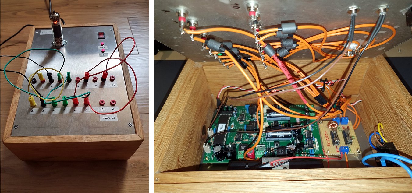
uTracer3 in service:

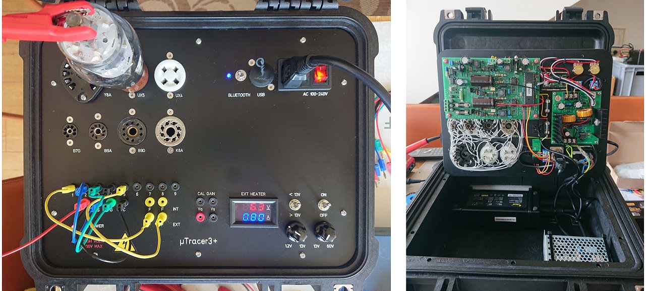
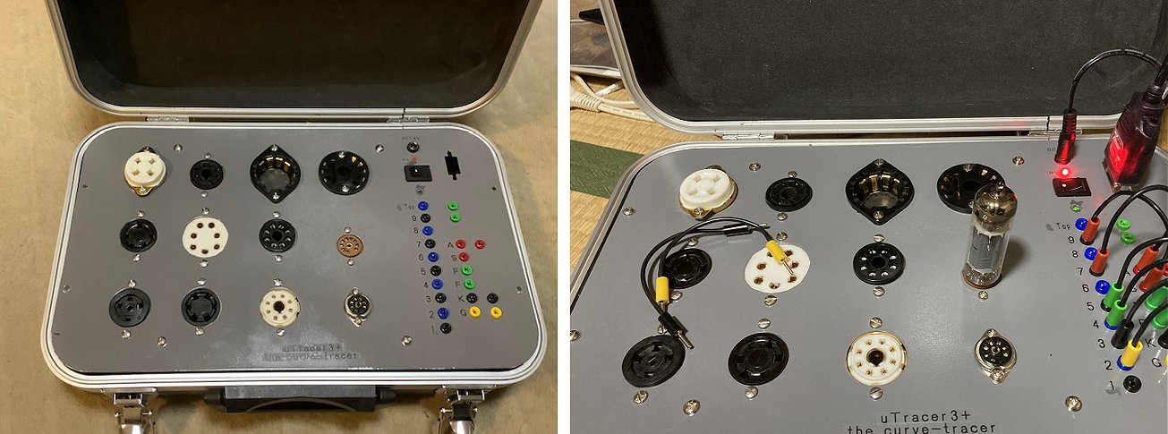
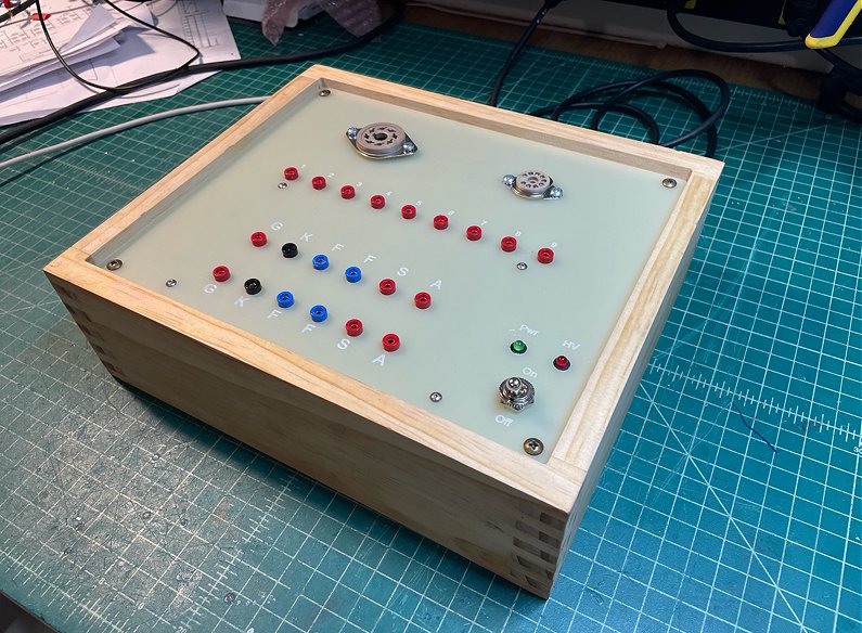
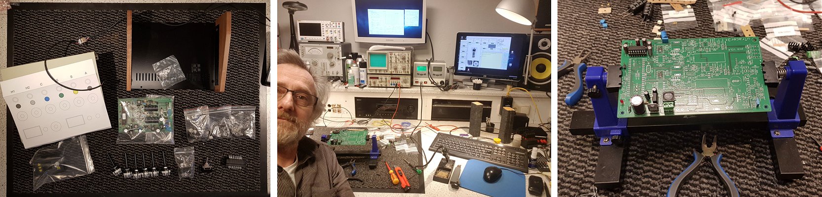
22nd of July 2026, Martin finished his magnificent uTracer3+!.
Hello Ronald,
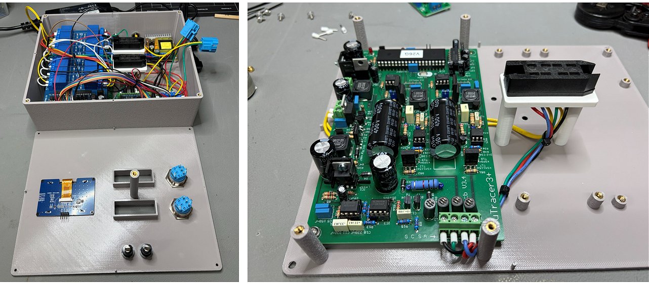
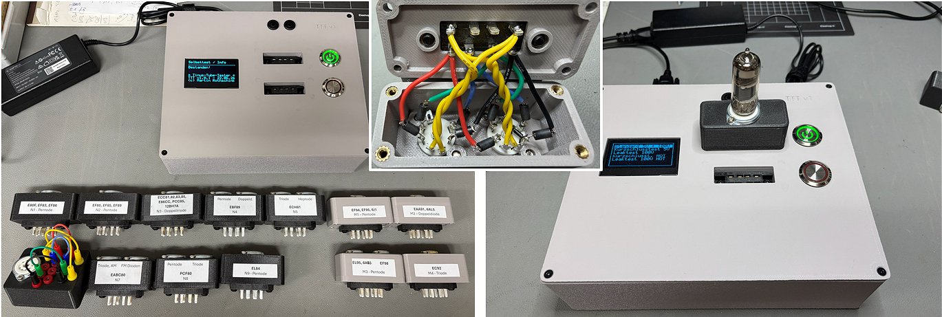
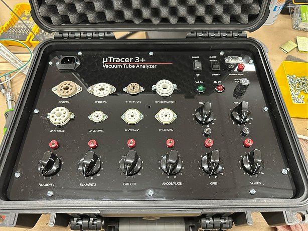
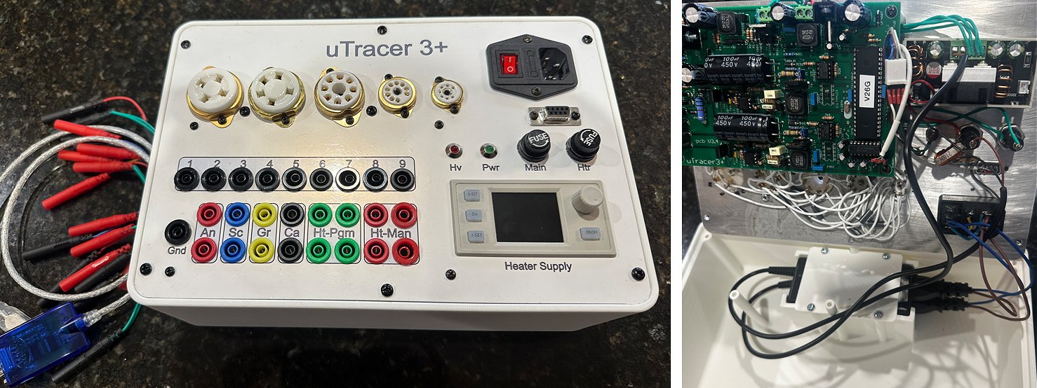
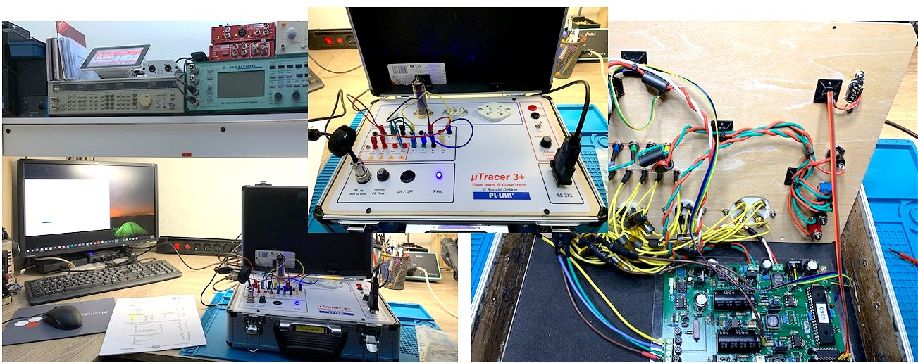
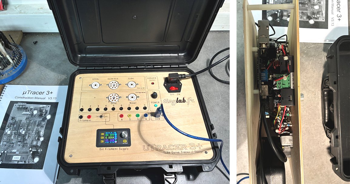
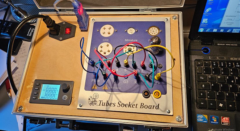
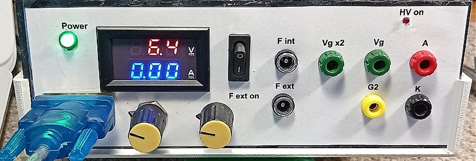
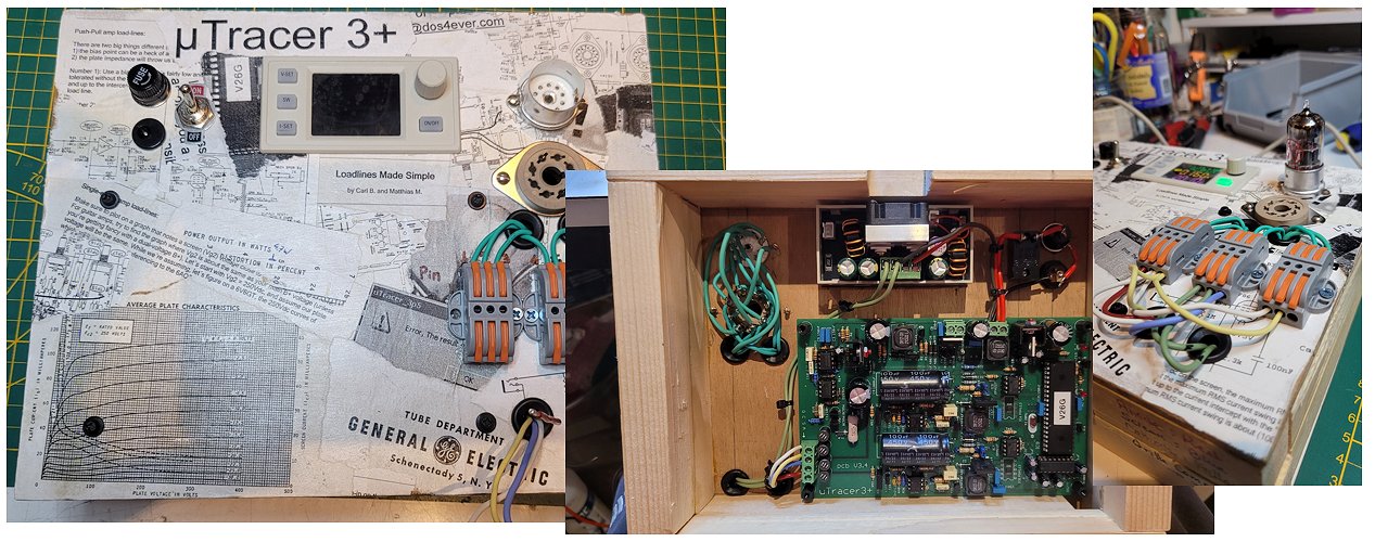
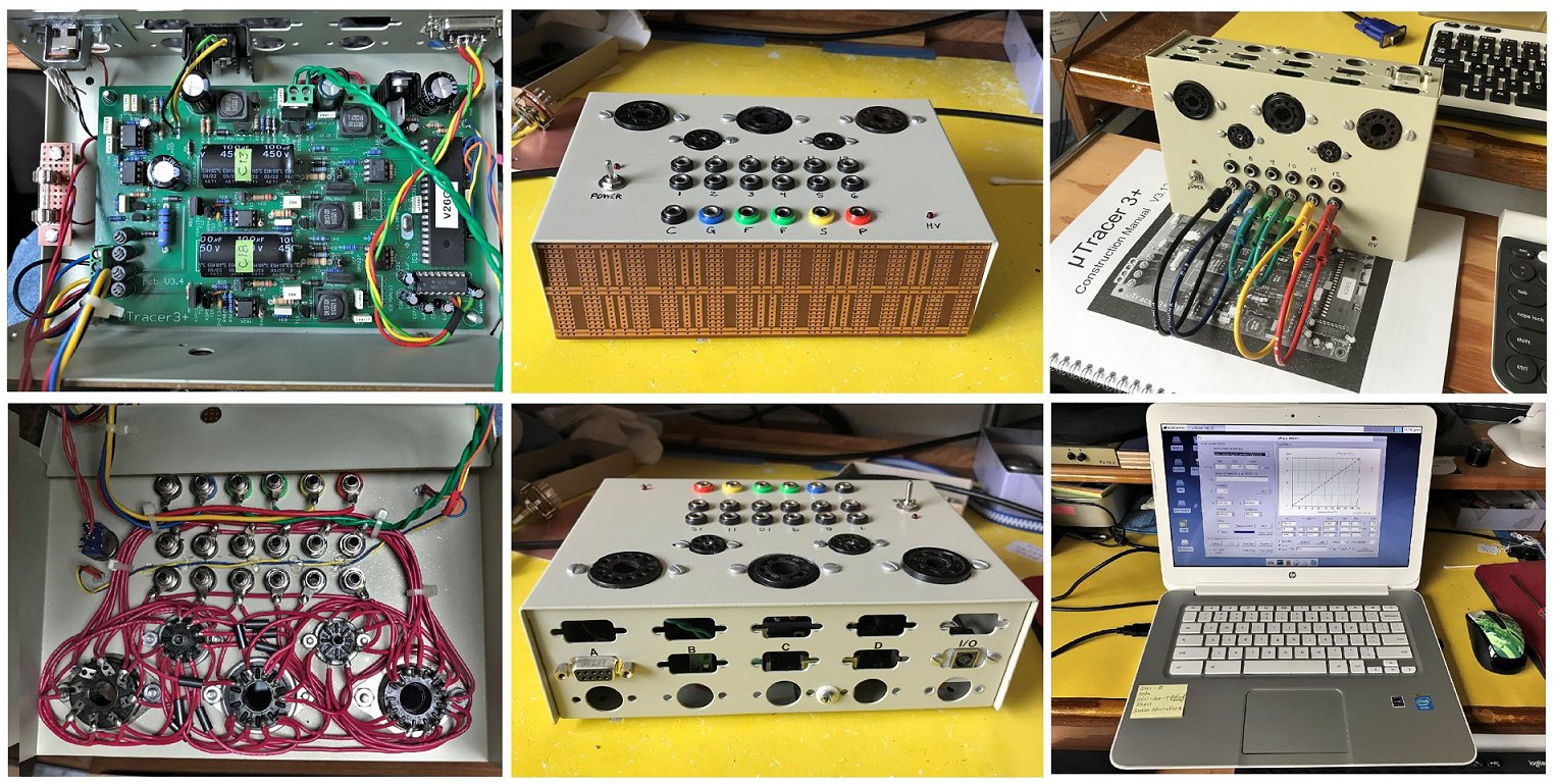
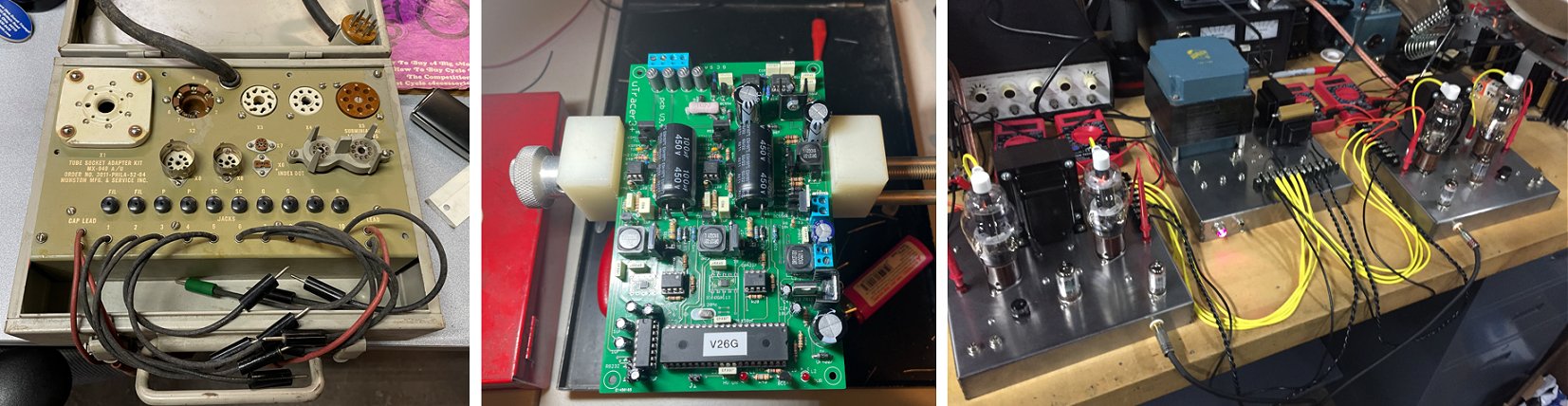
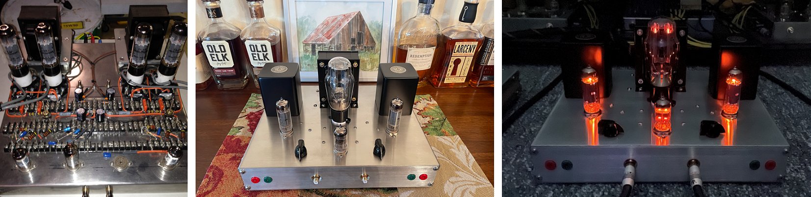
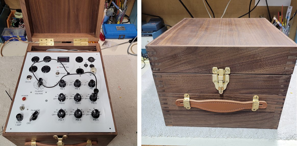
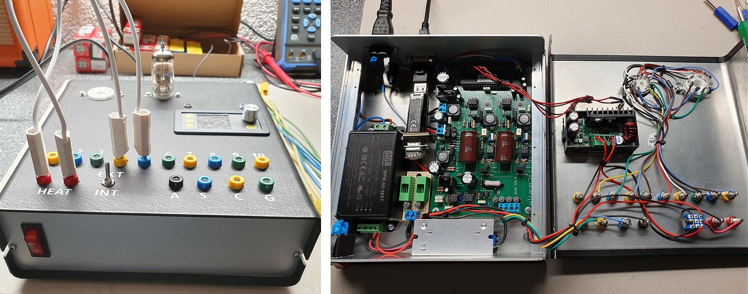
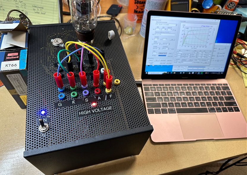
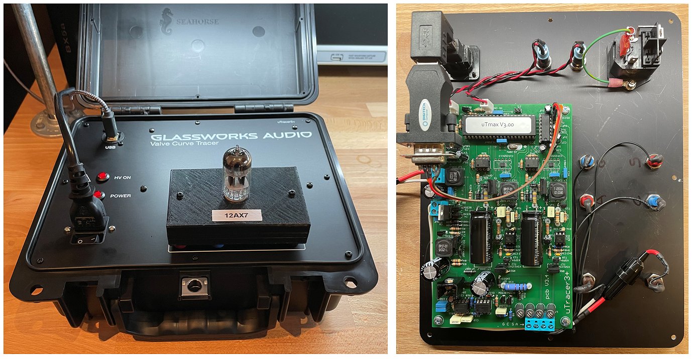
Unfortunately, it took longer than I’d planned. But my tube tester, based on the uTracer 3+, is now finished, and I’ve attached a few photos of it for you.
I’ve opted for a customised adapter solution for the tubes I use most frequently.
To protect the uTracer, I’ve also added an automatic short-circuit and leak-test, controlled by an Arduino Nano.
There’s a detailed description on the German Radio-Bastler forum: https://www.radio-bastler.de/forum/index.php?thread/32065-mein-r%C3%B6hrentester-auf-basis-des-utracer-3/
and a short video on YouTube: https://youtu.be/dy1wrZ7EVIQ (see below)
Regards,
Martin
14th of July 2026, Prentice send be a picture of his beautiful uTracer3+!
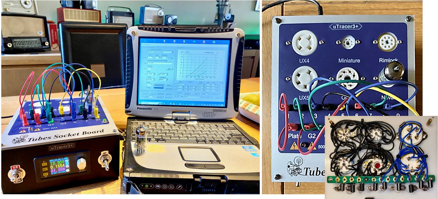
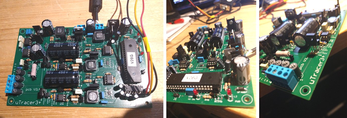
Please put me on the waiting list for the NXT! In the meantime, I started this uTracer 3+ in 2015-16, built and tested the board, and all the major parts were constructed, and then I had a major family emergency. Fast forward 10 years exactly, and I finally have it assembled! I will be using it in the next week, learning it, and hopefully all is well! Here is a sneak peek at the completed tester!
Thanks,
Prentice
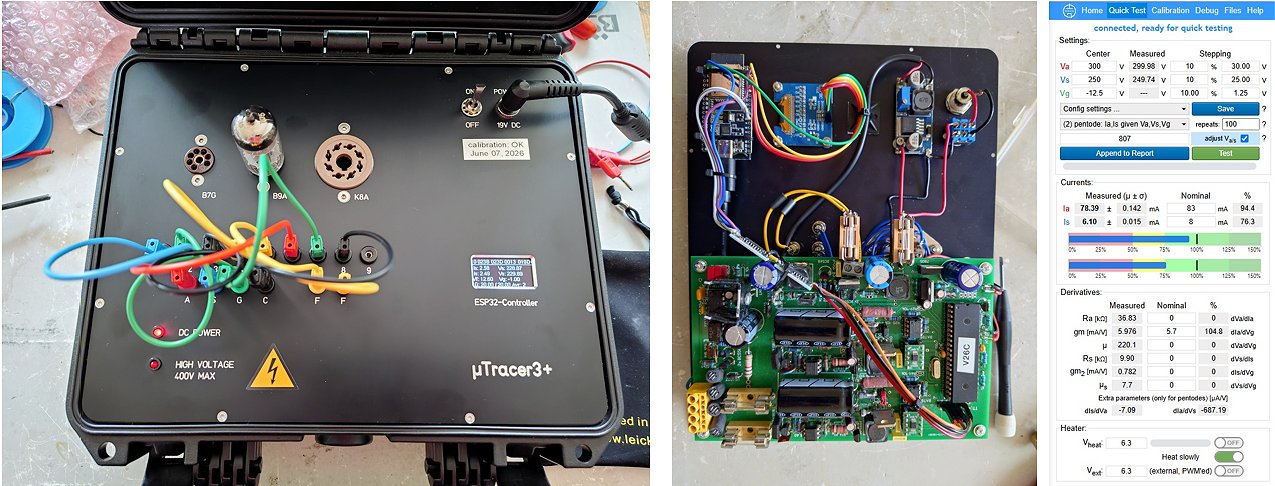
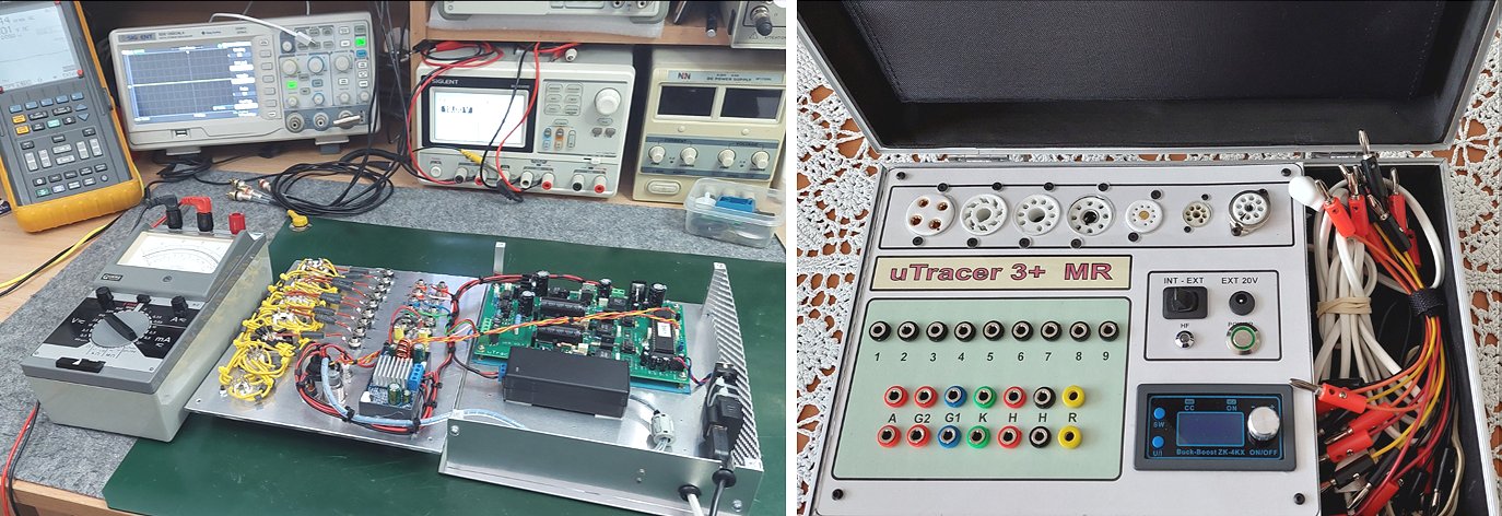
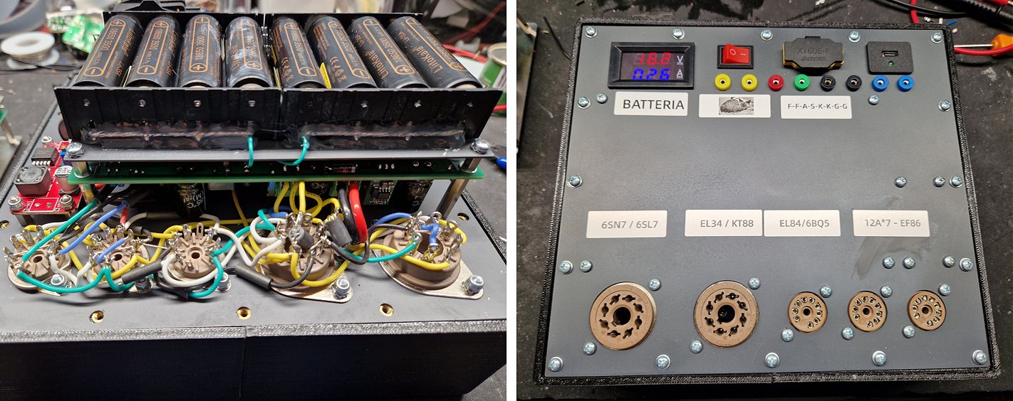
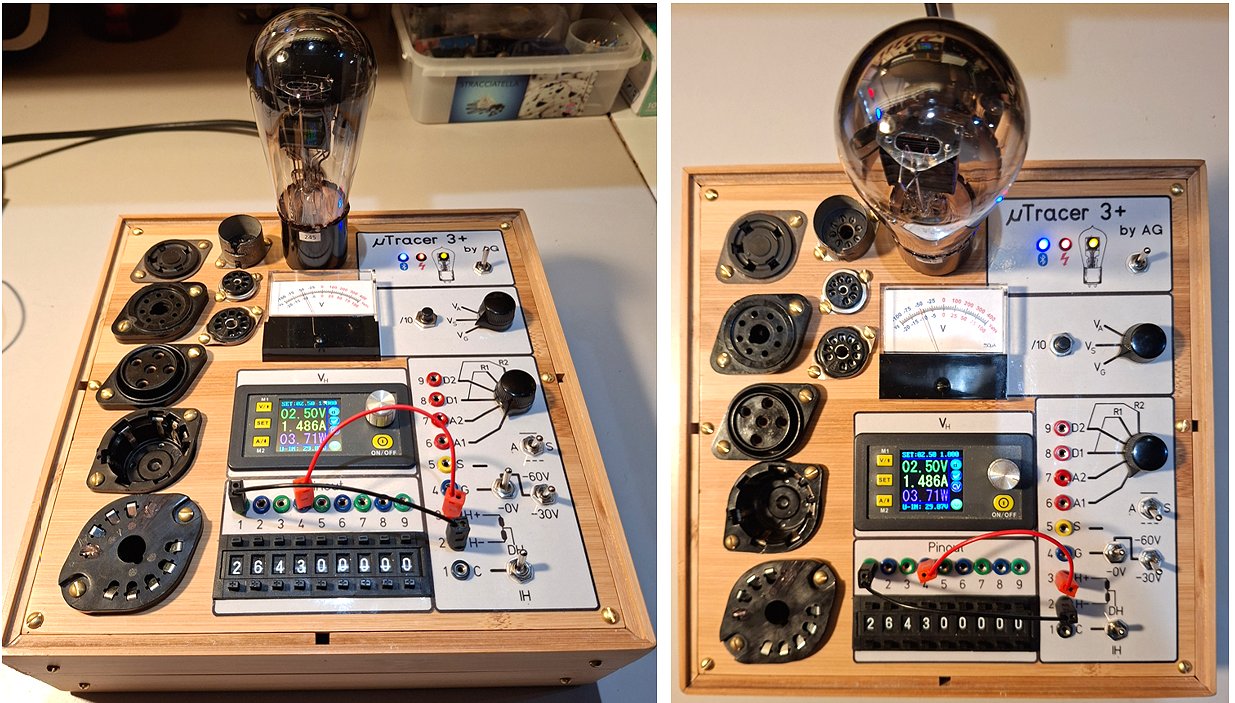
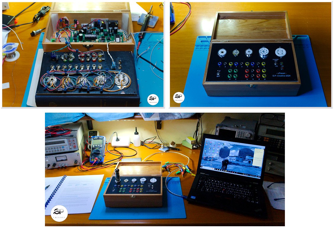
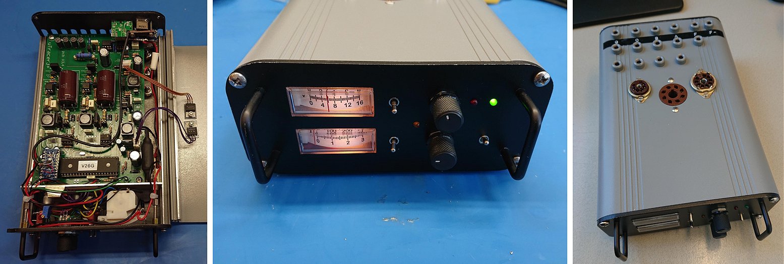
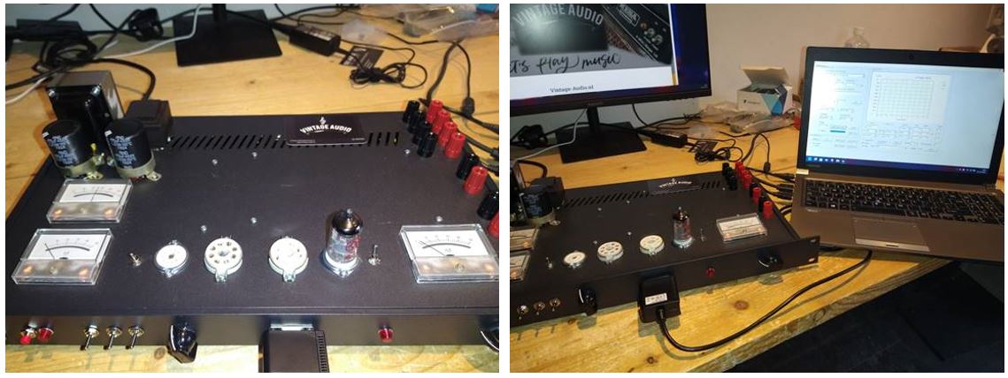
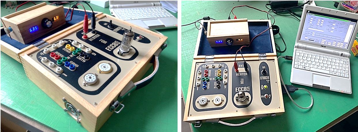
12th of June 2026, Alex sent be some pictures of his beautiful “regular” uTracer3+ (top row) and his new “mobile” version (bottom row).
The mobile version is controlled by an ESP32 board running Ihor Smal’s uTracerJS GUI.
Hello Ronald,
Even though my uTracer is already a bit older, I wanted to send you an update.
I built the 3+ model back in early 2016. I rarely used it, as I also owned two AVOs and other vintage testers. Then I acquired a RoeTest and parted ways with the older units. I had built the first uTracer into a nice case with an external heater.
Last month, I found a used uTracer board on a classifieds site. That gave me the idea to build a very compact, battery-powered tester for portable use. I finished it this weekend. Thanks to Ihor’s uTracerJS running on an ESP32 controller, I can operate the device via a smartphone instead of a computer.
I’m very happy with it—thanks, Ronald.
25th of December 2025, On Christmas Day 2025 Gerhard sent me a few pictures of his awesome uTracer3 and he is already looking forward to the uTracerNXT!

Hi Ronald,
Looking forward for the uTracerNXT in 2026.
I think you were planning keeping PCB size and mounting holes similar to the uTracer 3+ , which is awesome.
I recently 3D printed this great case and planning to put the uTracerNXT into it.
All the best,
Gerhard
Gerhard asked me to add:
I want to clarify that I am not the designer of this excellent case for the uTracer3+, and the posting incl. fotos are from the designer https://www.thingiverse.com/thing:5094091
Just wanted to make sure he gets credit, instead of myself :-)
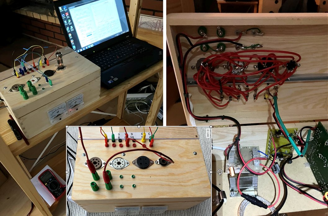
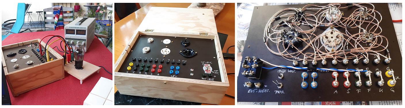
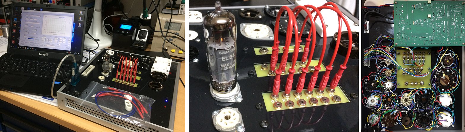
14th of November 2025, Heikki from Finland sent me a few nice pictures of his practical uTracer!
Hello Ronald & Marie-José,
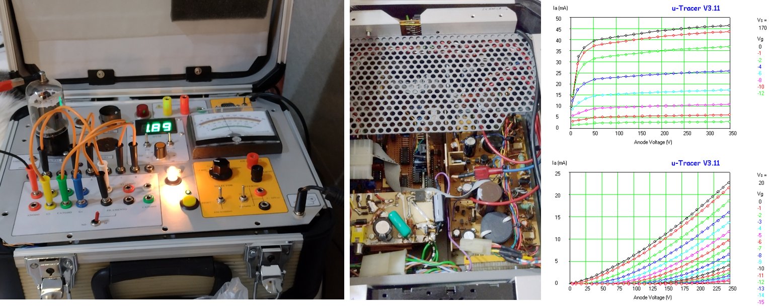
Here are a couple of figs. from my vacuum tube work station based on dos4ever PC board.
The wooden box has two advantages: easy to work with and two cooling openings :). The top plate is reinforced with an aluminum profile. It is also hoped, that easy wood work leaves some energy to the proper tube work itself. An external filament transformer is located inside the box and the filament voltage lowering resistor is attached to the binding posts at the top plate.
Thanks a lot for the marvellous design of uTracer!
Best regards,
Heikki
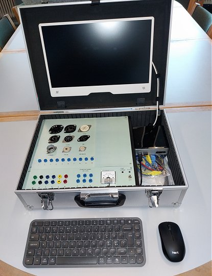
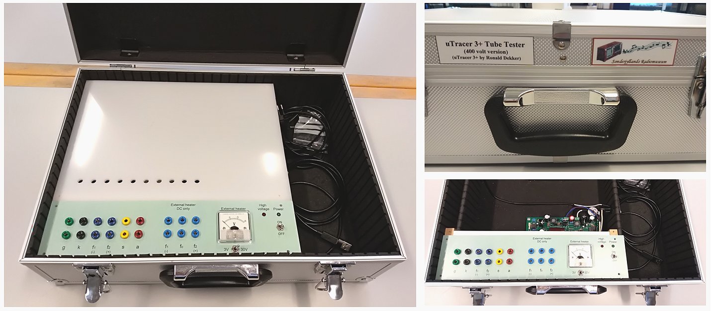
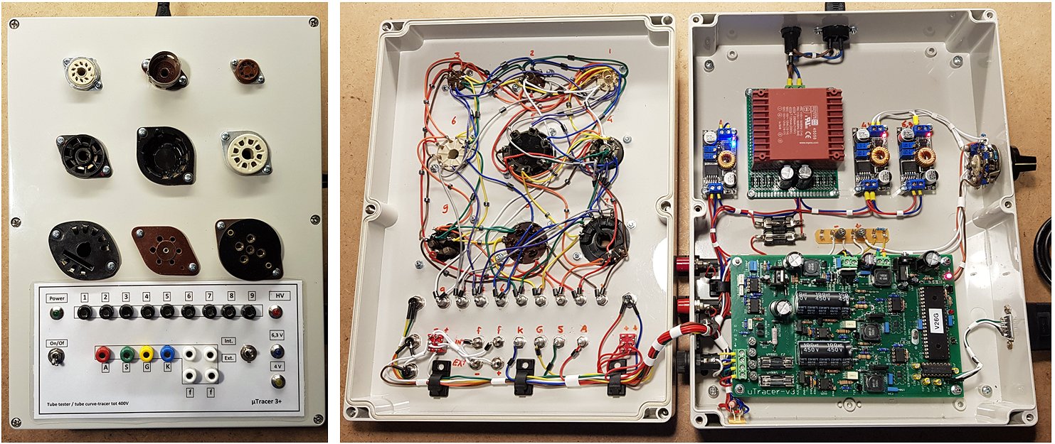
3rd of November 2025, Preben from the Sřnderjyllands Radiomuseum sent me a nice picture of their beautiful uTracer!
Hi Ronald and Marie-Jose,
Thank you for your efforts in developing and distributing uTracer kits.
And we look forward to following the development of the new NXTracer.
We are very happy with our uTracer 3+ here at the Radio Museum.
Attached picture of our version of uTracer 3+.
Best regards
Sřnderjyllands Radiomuseum
Preben
25th of Oktober 2025, After a small hiccup, Todor reports his uTracer fully functional!
Hello Ronald,
Thank you. You were right, the resistor was the problem.
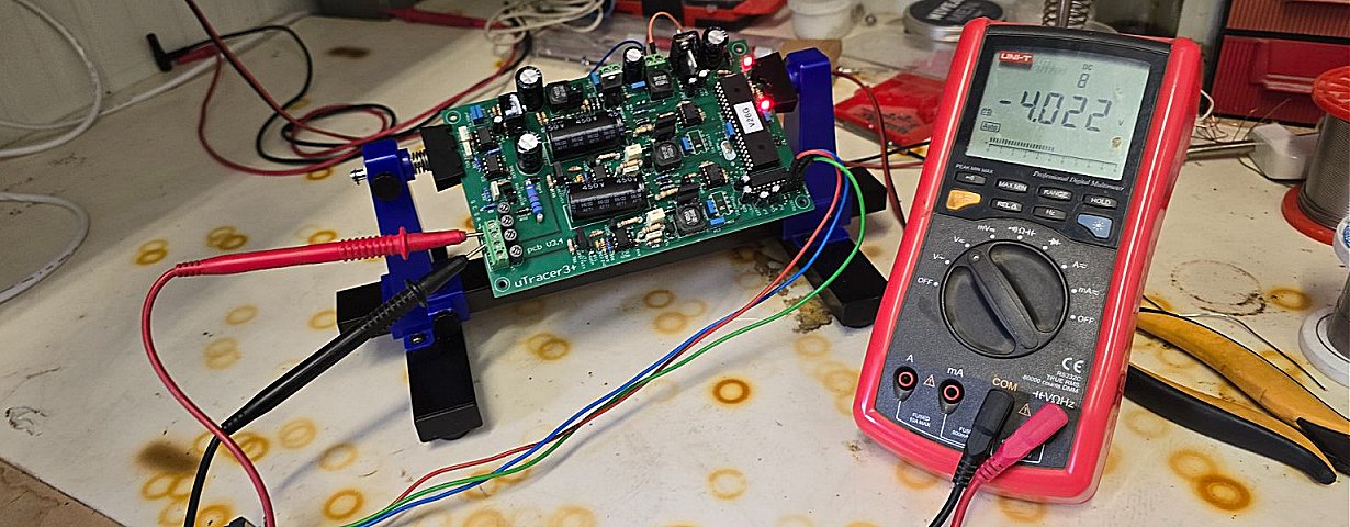
Everything is Ok. I'm sending you a photo of the final calibration. I just need to put it in a box. When I'm done, I'll send you a photo.
I wish you health and happiness in your family.
Todor
22nd of Oktober 2025, Frank reports his uTracer working!
Hello,
Everything is ready now.
First Tubetests works with no problems.
Only housing is missing and I have to build.
Thank you very much for this great tool.
Best regards
Frank
Mit freundlichen Grüßen
Frank
21st of Oktober 2025, Chris sent me a few pictures of his beautiful 3D printed uTracer!
Hi Ronald,
I would like to thank you for your brilliant uTracer design and for making the kit available to enthusiast like me. The kit and instructions are top notch.
I attached a few photos of my project. I 3D printed the case and machined the top plate on my CNC mill. For the artwork I just printed the legend on self-adhesive vinyl sticker paper.
Thanks again for your great work,
Chris
4th of Oktober 2025, Jedidiah reports steady progress on his uTracer!

I’m sorry to hear of your illnesses! I hope you find good health in the future.
I’m enjoying my build of the uTracer. I plan on using it for testing 01A dht’s. I see your note about placing a low resistivity pot in parallel to the heater with cathode connection to the slider. What does that allow to happen? I have my external heater supply set up with a 5k pot on an lm317. Does your suggestion give further control somehow and how would I monitor it?
Thank you again for all your work on this project and the gift you’ve given to the tube/valve community!
30th of September 2025, Tuukka sent me a few pictures of his fine uTracer!
Hi Ronald & Marie-José
Sorry to hear about your illness, good to know you are both OK now!
I have been very satisfied with the old version uTracer, anyway not having very much new tube projects lately it has not seen very much use.
I feel for you about the copied concept - and will surely let you, and buyers know about it if I ever see one.
Don't know if I ever sent you pictures of my uTracer build - here they are. Many tube radios and some amplifiers have been restored with it. Some "hot" tubes tend to oscillate while testing, I guess some more ferrite beads are needed.
Best regards,
Tuukka
30th of September 2025, Have a look at Philippe’s great uTracer and magnificent workshop!
Dear Ronald and Marie José,
First of all, I'm very happy that you and your wife have overcome these health problems. I wish you the bests in the future :-) I received your newsletter message just as I was about to send you some news about my own u Tracer, which I just finished ŕ few days ago ! I owned the kit since January 2025, but I hadn't yet devoted the necessary time to complete assembly and integrate it into a "box"...
The assembly went perfectly thanks to the very comprehensive documentation and the test procedure, as the assembly progressed..., which helps avoid errors and makes adjustments very easy. I'm sending you photos of the device fully finished and operational...
For the "box", I chose to assemble it in a small toolbox purchased from a hardware store. I find this makes it very easy to carrying with all its accessories and cords ... You'll see it in action on my bench on the photos !
It will be used mainly for maintaining and building tube audio amplifiers.
I'm just getting to use the software and haven't encountered any particular difficulties so far...
I was just wondering if it would be possible to add an LED to signal when the heating is enabled. The indication on the software is present, but I think it would be a nice added value to have it on the front panel of the enclosure.
If I wanted to add this indication, where would be the best place to connect this LED on the board? In parallel with the heating output, limiting the current in the LED accordingly? You'll also see that I've planned to be able to use an external power supply for the heating, but at this stage, the wiring modification you suggest in your documentation hasn't been made yet.
The photos and my short comment can of course be used for your website.
Best regards.
Philippe
30th of September 2025, Jean-Philippe made a beautiful compact uTracer!
Hi Ronald,
Bought in december 2024 and build in January 2025, my uTracer 3+ have been updated to be able to support 600ma.
It have been integrated in a small suitcase “Peli” like, with laser cut/engraved faceplate.
An external filament supply have been integrated. Thanks to the two presets allowing to choose between 6.3 & 12.6V.
Thanks also to the current limiting function allowing to heat tubes carefully… It’s however always possible to use internal heating (see int/ext switch).
I’ve only integrated wired tube supports for ECC8x, EL84, and EL34/6L6. Two additional sockets with associated micro bananas allows free wiring to test others octal and noval tubes. I never used them for the moment since I’m primary use uTracer for maintain guitar and bass amps…
There’s room for adding one more socket. It will probably be populated with a rectifier tube support in the near future.
Usb conversion have been integrated (with FTDI232) allowing to connect directly to modern PCs. I’ve already tested hundred of tubes.. works really fine.
Thanks a lot for the marvellous design of uTracer!
30th of September 2025, Have a look at the beautiful uTracer of Marian!
Hello Ronald and Marie-Jose!
I am very happy that your health problems have passed. I know something about it as a 77 -year -old young man.
My loss works perfectly and I am very happy. However, I think that for me there will be a more appropriate version of 1000V.
I will gladly order such a losing kit (uTracer6) as it is available.
Photographs of my device are available at www.facebook.com/marian.ryczan
I wish you a lot of health and serenity.
Marian Ryczan
Mrelektronik
30th of September 2025, Koen already tested hundreds of tubes with his nice uTracer! (in Dutch)
Hallo Ronald & M-J,
Hierbij alvast een mooie uTracer !
Ik had je finaal resultaat nog niet gestuurd denk ik -- want ik ging het nog beletteren -- maar dat is er dus nog niet van gekomen. Maar zo vind ik ‘m ook al heel presentabel!
Ik er heb al 100den lampjes mee gemeten.
Dankje voor het prachtige product en al de inspiratie & ondersteuning.
Gr
Koen
2nd of September 2025, Carlo finished his very beautiful uTracer and has a lot of learning to do!
Thank you very much Ronald!
Next step is to learn all to interpret well all the datasheet… moreover today I started to quick testing some ECC83 an ECC82 with the right parameters and all is Ok!! I had some surprises, some of my tubes will go to garbage, but I already have a queue of friends who would like to try their tubes.
Viva the Utracer!!!
Viva Ronald!!
17th of July 2025, Hans is very pleased with his uTracer!
Dear Ronald.
I attach a picture of it as it looks now. It's not really pretty - I am no graphical artist, but it works. As you can see I have added an external heater. Not so much because of the concerns others have had about the built-in heater, but because I sometimes need to test 6C33C-B and 3.6A at 12.6V is a bit much for the µTracer.
There is a small switch for the external heater - so when the meter is on, it is active. Power for the meter is a 9V battery switched on by a relay. The power consumption of the meter is so small that I suspect the battery will expire because of old age rather than use. Moreover, the meter works with as little as 4 volts. I wanted to avoid too many switches so the internal and external heaters have their own connections (a DC-jack). Not shown is the jack with two leads to connect to the heater.
I have prepared it for the -100V screen voltage extension. This also connects with a separate banana plug. The -85v supply is probably going to be a 555 based boost converter stabilized by a zener (actually a variable "zener" with a low voltage zener and to transistors - this is a much more temperature stable option than a high voltage zener). I have experimented a little with it, but boost converters are totally new territory for me - your pages helped a lot, but I may have some questions when reality kicks in.
As I said in a previous mail, I also plan to test the 600mA option. You mention that, although it seems stable enough, it has to prove its worth on the battle field. Have you had any responses?
Again: Thank you very, very much for your help!
Best wishes
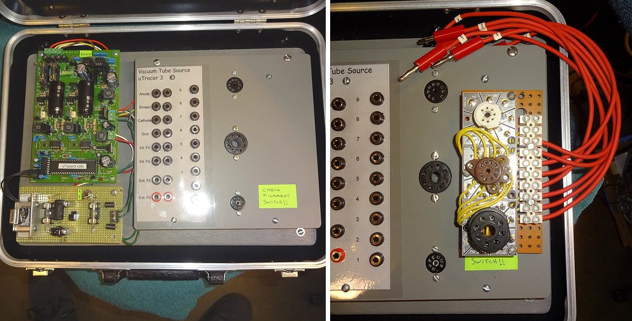
23rd of April 2025, Wow! The first portable, battery operated uTracer!
Good morning mr Ronald,
I attach some pictures.. sorry but i'm really bad taking photos... also speaking English. Basically, it's a uTracer3+ with a dc/dc boost to provide 19.5V with 3A, from 4 couples of 18650 Liitokala (3.7V 3500mAh, measured). Bms is placed under the metal plate where i glued the battery holders. A digital voltmeter/amperometer tells me the voltage of the battery pack and the current before the boost converter.
The XT60 is due to power the tube tester from an external power supply. A fuse and a diode are for battery pack protection. On the corner added a small USB C 4S liion charger, it takes some hours to charge the pack, but it will last for tens of teste, enough if i have to check tubes before buy them.
To have a fully portable system I added an ESP32 board with Boffin's software, so i can use it from a web browser both from a phone or with my pc at home (the ESP32 starts an acces point if the saved network is not found). Finally, i swapped the 7805 with a Murata OKI78 regulator due to supply the ESP32 and the PIC16 of the uTracer3+. An ugly 3D printed enclosure protects everything even if i keep the instrument inside a bag.
Best regards
Denis Brioschi
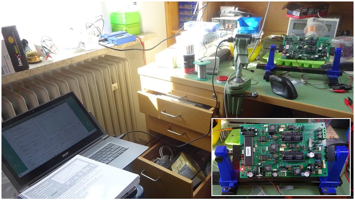
19th of April 2025, Christoph’s uTracer is operational! Always nice to see somebodies working place!
Dear Ronald & Marie-Jose,
Thank you very much for the letter and the informations about the uTracer. I am very sorry to hear that your health has caused serious problems. As we get older, health is not everything, but without health everything is nothing. It is really shameless to come onto the market with copied replicas, whoever does this. Unfortunately, there seem to be more and more people like that, even from China, who are masters at it.
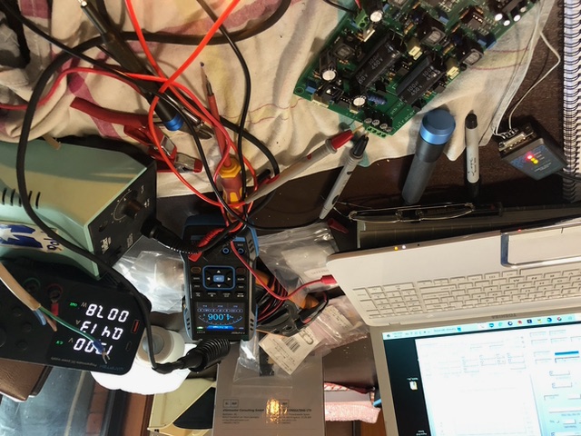
Please find attached photos of my status. I'm testing the “resistance straight” today. I have problems with the GUI with the 20mA setting of the measuring field, which prefers to display 25 mA max vertically. But I have only just started to try this out. Unfortunately, there were no illnesses, but house repairs and renovations in the way, so here are two pictures of the laboratory table, which also contains some other developments. Anyway, so far everything is in the green Zone.
I wish you both a Happy Easter and very good health and :: Carpe Diem.
Kind Regards
Christoph
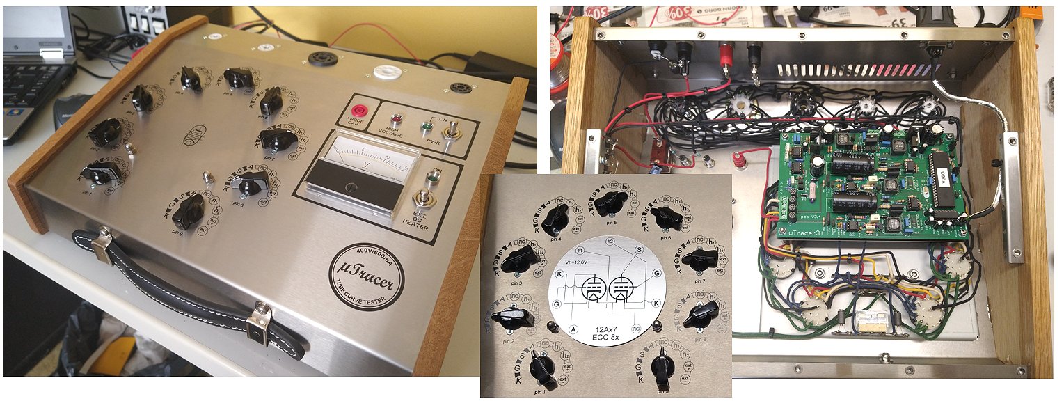
24th of May 2025, “Mr Q” from Finland sent me some pictures of his magnificent uTracer!
Hello Ronald!
Casing for uTracer is finally finished and I'd like to share these photos with you. My workmate Jani (who made those fine silk-screen printings) said this looks exactly like different "gadgets" in -50's -60's agent-/ science movies ?? I'm happy to see my goal to captive some aesthetics of that golden tube-era is succeeded!
As a "cherry at top of the cake" we are currently making changeable charts for most usual tube types to guide correct rotary switch positions. Jani makes them with laser engraving using 2mm plastic sign material with black body/aluminum top layer. Currently we have only this ECC- proto finished...
If you find my/our work any good, please feel free to use these photos anyway you like.
Happy summer to You & Your family!!!
Sincerely,
Mr. Q
British Intelligence Agenc...(ok, Simo from Finland)
9th of May 2025, Terry sent me a few pictures of his practical uTracer3
Hi,
I had snapped a couple of pictures of my uTracer3 build but I forgot to include them. I thought you might be interested.
I had an old Tektronix case to house the tester. I found a large supply of vintage, 12” banana jack cables (I think from a phone switchboard unit) to use for the interconnects and also constructed the external socket board for testing two tubes at once. It all works very well.
I tested a lot of tubes on this uTracer but drifted away from vacuum tubes for a number of years but am now back testing and selling a large stock of vacuum tubes that are stored in my garage!
Terry
25th of April 2025, António from Portugal sent me a few pictures of his magnificent uTracer!
Hi Ronald,
I hope you and your wife are in better health.
The uTracer arrived on April 14th.
I put it in its final box and it is "Alive & Kicking", after the repair, you so carefully done.
It works perfectly.
I added some features:
- A voltmeter to monitor Vg, Va and Vs, with two scales.
- Additional voltage source in series with Vg (0V, -30V and -60V)
- Separate power supply for the filament of the tube under test.
- A switch for Va and Vs voltages, pulsating or continuous.
- A switch for cathode with direct or indirect heating.
- Diodes/rectifiers test (D1/D2/R1/R2) “a la Metrix”
- Bluetooth connection.
It uses the AVO codes in the rotary switch to select the eletrodes in the pins, except the filament,
that it is connect via two banana cords, because I dont trust the rotary swicth to hold to much current.
Just added a few tube sockets the ones I use the most, but will use na add-on box with others sockets.
Thank you for your wonderful project and for your enormous patience and generosity.
Kind regards and best wishes for a speedy recovery,
António Gomes
25th of March 2025, Mariano finished his excellent uTracer!
He Ronald,
I have finished assembling the uTracer, which was delayed due to the flooding in Valencia.
I have assembled the uTracer separately from the valve sockets, which are in a separate box and can be used for both the uTracer and analog tracers.
I attach some photos of it in operation.
Thank you,
Mariano
21st of March 2025, Jordy reported his uTracer finished and working!

Yes, the Utracer has now been finished for about a month. I wanted to have one because of a broken Ampeg SVT amp, where I suspected the problem was with the power tubes. However, due to the amp’s construction, I couldn’t easily measure or test them as I did before owning the Utracer. At the same time, I was getting tired of testing tubes by ear, eye, DMM, and chopsticks, so it was about time to build a proper tube tester.
Building the Utracer, including soldering and calibration, went pretty smoothly, and I didn’t encounter any uncertainties thanks to the well-written construction manual. However, I did run into a very frustrating problem: the Utracer worked on an old PC with a COM port but not on my workshop laptop (where I was using a cheap adapter). I emailed Ronald about this, and he responded very quickly (absolutely great). Unfortunately, Ronald didn’t have the exact solution, so I decided to take the device to the ICT department of the school where I teach. The issue turned out to be that the header I used caused interference and/or bad connections. Important to mention: this was not the header provided in the kit, but rather an 8-pin IC socket with some poorly soldered wires.
Once I soldered the wires directly to the COM port, the problem was solved immediately and it worked with the 5euro’s adapter/converter. Once the PCB was finished and the COM port issue was resolved, I put everything in a housing. I used ferrite beads that were larger in diameter than the solder wire (since I couldn’t find the exact size I needed), but I solved this by looping the wires through them. So far, I haven’t encountered any issues like oscillation.
I installed four tube sockets, while I probably only going to use the 8-pin and 9-pin ones. I haven’t come across 4-pin and 7-pin tubes (yet?) when repairing guitar amps, but I included them anyway because otherwise, the panel looked too empty—and you never know what kind of tubes you might run into.
In hindsight, it might have been better to build it in a plastic enclosure instead of a metal one. The housing is grounded, and if a banana plug accidentally touches the case, something gets shorted an the adapter disconnects. At the same time, this was a housing I already had lying around, so it felt like a free enclosure.
Lastly, the housing clearly shows that I’m very impatient when it comes to using a drill. The plugs are not level, and if I need to drill anything other than a simple round hole with the right drill bit, I just start hacking into the metal.
All in all, I’m very happy with the Utracer.
21st of March 2025, Lucky from Australia got his uTracer working on a very full kitchen table!
Hi Ronald and Marie-Jose,
Even though my tools were locked away in another house I was able to get an enough tools to get the job done, just wanted to report I have 1 µTracer built and calibrated. I had no problems with Win 10 Home edition just need a case and how to arrange it, haven’t tested and tubes yet but hard bit is done.
Yes I know its a mess done on my kitchen dinning table but it worked
Regards Lucky from Australia
23rd of Januari 2025, Simo is very happy with his uTracer and managed to silence his wife!

Hello there!
I just finished soldering/ testing your 3+ kit. It works PERFECTLY because of your fine&detailed instructions. Building was a great fun, too shame this board is ready now. One of the finest aspects in your kit is having construction manual in a physical PAPER form! Please don't ever forget this nice handshake with these "old timers" like me.
You should have seen my wife's face when I tried to demonstrate uTracer in action for her.. She didn't say a word, but I could very clearly read: "How in heaven, a grown 58 year old guy is first sitting quiet for 15h of soldering, just to get so excited about three idiotic curved lines on laptop screen" Oh, man!
This old 12AT7 from junk-box is my first attempt to learning to use the tracer. I think I will be pretty ok after few more hours of training...
Nice to have some real data after 40 years of just GUESSING condition of tubes!
Close-up of EL34 is especially for you, I could not resist to warm up this beauty because of it's legendary brand (Yes, I have read about your work history!)
-simo
21st of Januari 2025, Matthieu from France has become a happy customer!
Hello Ronald and Marie-José,
I'm very pleased to announce that I've finished my STEP1 Temporary box µTracer 3+ :-))
I'm planning to build a nice chassis with rotoswitches like my Metrix 310B, but for the moment I'm okay with this little and compact enclosure made with my 5 years old boy!
No ferrites for the moment... and the results is quite good. I will add them when I receive the next components order. I put an external power supply for the heater.
I use WAGO interconnect for the matrix (cheap and effective for the moment).
The quick test is perfect for ... quick test! Great feature.
I like the works at boffin.nl for the load line tool.
I've reached the 200mA compliance limitation with the EL34 at VG=0 / -5, maybe a µTracer V6 one day...
It's a nice tool, the construction manual is perfect! (Maybe just put the two 10k/1% in the kit for the calibration)
Congratulations for this work, your skills are awesome!
You can follow the construction of the kit on my website:
https://www.projetg5.com/phpbb3/viewtopic.php?t=6577&start=15
Have a great week.
Best regards,
Matthieu (an happy customer)
13th of Januari 2025, Walter reports another uTracer3 in service in Italy!

Hi Ronald, how are you doing?
A few years have passed since the last email exchange!
Just to inform you that my uTracer3+ was actually completed a few weeks after I received the kit (April 2022). Four months later I relocated abroad, and I had no longer a chance to play with it... Recently I spent Christmas holidays in Italy, and I decided to take a couple of photos. As you can see, I recycled the metal case of an old UPS (very convenient to save space on my crowded bench!). Everything fits inside, including an extra PCB for the external filament power supply and its separated power brick.
I removed the MAX232 chip (parked on the black foam) and I connected a RN-42 module (it is not visible in the photo, since it is between the front side of the metal case and the plastic "panel". This way I connect to uTracer via BlueTooth.
The external filament power supply board sniffs the data sent to the PIC and automatically switches to a programmable DC-DC converter when a modified command is detected. This command is sent by a custom version of uTmax GUI, simply replacing the unused zeros in your protocol with FF (this modification is ignored by uTracer). In brief, I can choose between internal and external filament voltage source without the need for any mechanical switch!
Thank you for creating and supporting uTracers!
Have a nice day and ciao,
Walter
27th of October 2024 Andrew from New Zealand sent me a picture of his stunning uTracer with rotary switches!

Hi Ronald,
I thought I better send you some photos of the finished product!
It's a tight fit in a Nanuk 909 case with two laptop PSU's (one for the utracer and the other for the external supply).
I used ferrite beads liberally and everything is working well.
Kind Regards
Andrew Parsons
New Zealand
1st of October 2024 Jonathan from Holland sent me a few pictures and a testimonial (in Dutch) of beautiful and professional uTracer!

Beste Ronald,
Een tijdje geleden heb ik de Utracer 3+ kit bij je aangeschaft. Inmiddels zit hij in elkaar.
Het was een erg leuk project om hem in elkaar te zetten. De kwaliteit van de print en de onderdelen zijn erg goed. De handleiding is geweldig! Het solderen verliep perfect en alle tests heb ik succesvol doorlopen.
De behuizing maken was ook een leuke uitdaging. De bovenplaat heb ik met een lasersnijder laten uitsnijden via een collega, een koffertje (B&W type 3000) scoorde ik via Marktplaats en met een paar 3d prints kon ik alles netjes monteren.
Ik ben erg tevreden met he uiteindelijke resultaat. Zie bijlages. Erg leuk dat oude buizen techniek samen komt met moderne techniek zoals lasersnijden en 3d printen.
Als voorbeeld heb ik de behuizing van Nebojša gebruikt.
De buizentester werkt erg goed. Eindelijk heb ik goed zicht op welke buizen nog bruikbaar zijn of welke buizen echt op zijn.
Ik had al wel een Amerikaans buizen tester (Hickok 600), maar daar kon ik lang niet alle buizen op testen en die gaf lang niet zoveel informatie over de staat van de buis.
De Hickok mag dan ook met pensioen. (nee hij gaat niet weg) ??
Inmiddels werkt de uTracer ook via Bluetooth.
Mvg,
Jonathan
30th of July 2024 Erik from Holland sent me a few pictures and a testimonial (in Dutch) of his fine uTracer that one way or the other reminds me of the Enigma coding machine!

Dag Marie-José en Ronald,
Ik heb mijn u-Tracer 3+ in elkaar gezet en hij werkt prima!! (Teleurstellend te zien dat ik best veel zwakke buizen heb ? ??)
Ik heb een paar foto’s van mijn creatie bij gevoegd.
Ik heb gekozen voor een “stekker” optie die ik in principe kan afsluiten. Alleen wanner bv. Een externe voeding of dat er een weerstand gebruikt moet worden voor het testen van gelijkrichter kan ik die gebruiken. Ook zijn hier de Hoogspanning direct van de Elco’s naar buiten gebracht voor het testen van een “Magic-eye”.
In de andere gevallen gebruik ik de duimwiel optie die eronder zit. Ik heb voor elk type buis een 10-cijverige “code” die ik daar aangeef. Buis in de juiste socket en meten maar. Werkt super!
De stroom door de schakelaar gaat nog binnen spec, echter voor de hoogspanning niet. Wat ik hier heb gedaan is dat voor de hoogspanning aansluitingen ik altijd 1 contact heb overgeslagen tot de andere contacten en de het midden contact. Hierdoor is de kans op overslag minimaal. Niet schakelen onder spanning en tot nu toe geen problemen ondervonden.
15th of July 2024 Joe, “the tube amp guy” is very pleased with his uTracer3!

Hello,
I thought you might like to see another uTracer curve tracer completed and in service. I love this machine and really enjoyed the process of building it and learning how to use it.. I didn't try to reinvent the wheel and copied the idea for the chassis box and layout from another one of your customers that you had previously posted on your webpages.
It doesn't replace my Hickok 752 or EICO 667 for most amplifier service work. However, I think many of my clients will find this easier to relate to and understand rather than a 60 year old tube tester.
Thanks very much, enjoy your summer,
Joe
The Tube Amp Guy
www.thetubeampguy.rocks
1st of July 2024 Jim sent me a few pictures of his fine uTracer!

Hallo Ronald,
Eindelijk is m'n tracer volledig klaar. (wat een leuk project!) De inbouw heeft wat meer tijd gekost dan het bouwen van de kit zelf. Uiteindelijk gekozen voor een plastic fligtcase met een PCB frontplaat. Ik ben zeer tevreden met het resultaat.
Bijgevoegd enkele foto's.
Met vriendelijke groeten,
Jim Coun
10th of March 2024 Gianni finished his superb uTracer!!
Good morning Ronald,
I wanted to inform you that I have successfully completed the construction of the 'uTracer'. I am pleased to report that the entire process was enjoyable and smooth. The GUI worked flawlessly, and the assembly was carried out meticulously following the instructions provided in the manual. All tests were passed with satisfactory results.
I have already recommended this tool to numerous valve enthusiasts. Now, I will dedicate some time to thoroughly study the user manual in order to become familiar with the measurement procedures.
Thank you once again for your availability and support.
Best regards,
Gianni
24th of January 2024 Danny from Belgium is very satisfied with his very beautiful uTracer!
Beste Ronald,
Na een paar hickups ( BC559 in de grid defect ) is mijn uTracer3+ volledig klaar!
Ben er uiterst tevereden over , intussen een paar EL84 , 6V6 , 12AT7 , ECC82.
Ik had eerst problemen met oscillaties bij het testen van EL84 maar als je eigenlijk alles goed volgt bij het bouwen en de tips over o.a de ferriet buisjes enz… kan het niet fout lopen.
In bijlage een paar foto’s ;-)
Nogmaals dank !
Danny
2nd of January 2024 Mike from Tennessee was the first to finish his uTracer3+ in the new year!
Ronald, it’s a thing of beauty.
Let me get it into a proper enclosure and by Feb I should have an order in for the version 6 model.
Excuse the workstation. First two tubes tested following calibration. JJ 6sn7, first showed both halves literally dead matched up to 400v. Another showed a fair separation of the halves. It is awesome to see overlays of 4 triodes!
The only hiccup I had was I believe R45 had a deceptive hole, I mistook a via in line for the correct hole. While visual QC as I completed a module, found it. While reworking I broke the already installed BAT86 adjacent. Thankfully you supplied ONE Extra! Many thanks.
Additionally, was working on New Years Eve and (not drinking!) got tired early AM and installed t14 backwards and t9 correctly. Found dying a secondary visual, no harm, no power applied. I reworked the FET no issues.
It dialed in like it was factory assembled. Zero defects, the manual is stunningly complete and precise. I only wish I had a small percentage of your Solid State skills!
Happy New Year sir to you and yours. I have started 2024 with a uTtracer!
Mike in Tennessee
30th of December 2023 Roberto from Argentina sent me a fantastic report of his amazing uTracer!
Hello Ronald.
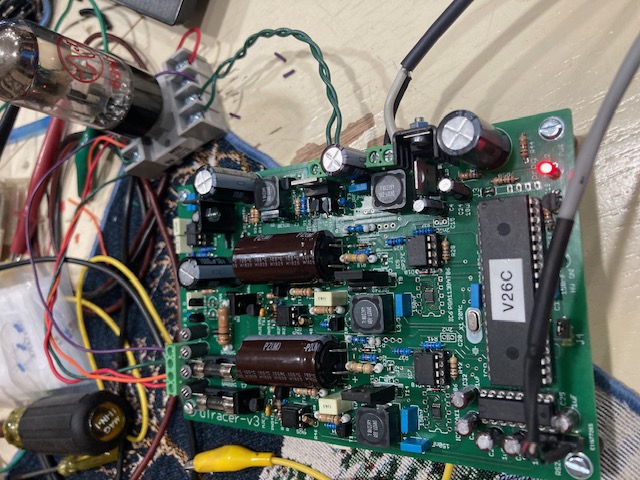
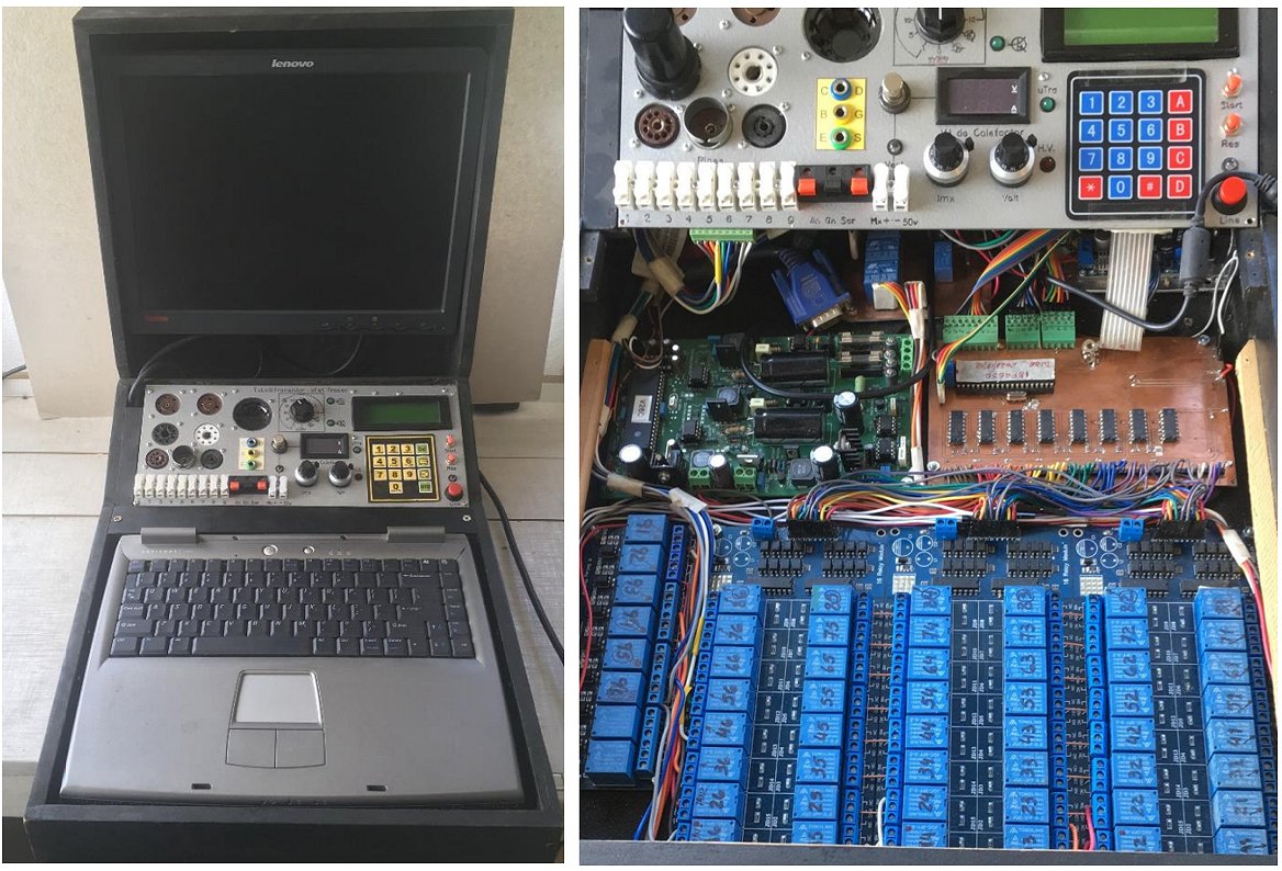
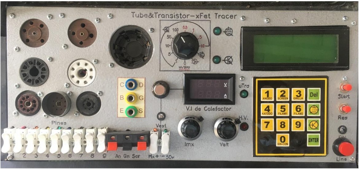
I was finally able to finish my tube tester-tracer. I integrated an old laptop, the uTracer, and an interface that I built based on a 18F4550 Microprocessor into a single equipment. This performs the function of assigning each of the pins to the uTracer buses. It is operated from a 4x4 keyboard, with a 16x4 display. The program starts by requiring the heater voltage to be reduced to a minimum to avoid possible damage to the next tube under test. Tubes and transistors can be tested. Everything is selected by keyboard. Once the type of measurement, tubes or transistors, has been chosen, we proceed to define the heater voltage and the pin assignment for tubes. Once this is done, it is passed to the uTracer function, which must be parameterized to start the measurement. I used a matrix of 54 relays for pin assignment, variable power supply for heater (I do not use the uTracer one), a 5 VDC supply for the relays and the interface Microprocessor. I have arranged several sockets for tubes and terminals for transistors. There are also terminals for the 9 pins if the tube under test does not have a socket on the equipment. The regulated and current-limiting heater power supply, with variable voltage from 1.1 VDC to 30 VDC. A central button allows you to use an external source. A rotary key is used to select Transistor tests.
The interface is in Spanish, I am from Buenos Aires Argentina. On YouTube there is a video about the operation of the equipment in tube testing. Everything done for this project is available to anyone interested.
Just have to write to my email rlopezsantoro@gmail.com
The video is in : Roberto Lopez Santoro, Buenos Aires Argentina https://www.youtube.com/watch?v=4tQHaiSvo3U
Roberto Lopez Santoro, Buenos Aires
Argentina
27th of November 2023 After a few hick ups with a faulty COM cable, Tim from Holland is happy to report his beautiful uTracer3 working !
10th of October 2023 Dave from Denmark, in all modesty, reports his uTracer working!
I am happy to report that there is yet another uTracer3+ in operation here in Denmark! It's working fine - although mine is not pretty it is very functional.
Many thanks for creating such a wonderful device.
Dave
6th of September 2023 Peter from the U.S.A sent me some pictures and an enthusiastic testimonial of his beautiful and compact uTracer!
Dear Ronald and Marie-José,
Your first-class µTracer 3+ kit and excellent manual arrived well packaged. I enjoy the "Greetings from Holland" card you enclosed. You have done such a great service for all of us by designing this amazing device! It was a pleasure to build, test and calibrate it. Everything tests as written in the manual. I used a case from an old 5-port VGA switch. It was just the right size to fit the PCB and tube sockets that I need. The box even had a stamped hole in the back made for a DB-9 connector (10 of them, actually!). I covered the front rotary switch hole with a decorative piece of IC perf board. A modification I made was to move the -40V IC regulator to mount on the back panel to help cool it since the box is so small.
The µTracer GUI program runs very well in my HP Chromebook computer using an FTDI USB serial converter. I used the dnschneid/crouton script from GitHub to make a chroot environment to install Linux, Debian 10.13 (Buster) i386 architecture (32-bit). Then I installed 32-bit wine 4.0 to run the µTracer 3+ (32-bit) GUI. I also tested it to run successfully on Windows 10 as a backup computer. My next step is to begin analyzing my collection of about 400 vacuum tubes.
Best wishes to you and Thank You!
25th of July 2023 Paul sent us a few pictures of his very nice uTracer!
Marie-Jose and Ronald,
I wanted to say thank you so much for this great tool.
I finally got mine together in an enclosure and started measuring/sorting some of the surplus tubes I have.
The uTracer works great and produces fast, quality results.
I've attached some images of the final build and a shot of an I-V test of a really nice 1958 RCA 6AK6.
Thanks again!
Paul
25th of May 2023 Milad sent me a few pictures of his truly amazing uTracer!
Hello Marie-José and Ronald,
it's been a while since I bought the utracer3+ but I finally finished my build. I decided to take inspiration from my Müter BMR 95 that I use to test CRTs. I bought a case and designed the rest around it. The skeleton that holds the PCB and the power supply is 3d printed and the top plate is acrylic that was laser cut and engraved. I'm really happy how it turned out, although I might exchange the acrylic for something else as it's a real fingerprint magnet.
I included a separate power supply for the heater that can be activated by a switch. It supports voltages up to 30V and should be able to go up to 1A.
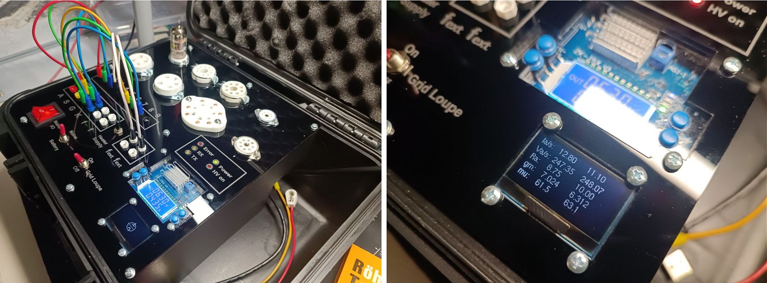
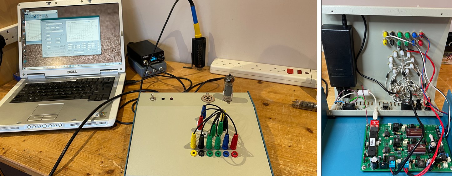
Instead of using the traditional utracer GUI I opted to use Ihor Smal's utracer ESP32 interface (can be found here: https://boffin.nl/wp/utracer-and-esp32/). It works well and also shows the measured values on the little OLED display. With that I don't need a laptop to do measurements as it can be done via any device that supports a web browser.
The idea was to take the whole tester with me to test tubes in the field (for example at conventions). Therefore I also added the option to supply the whole system with power via a USB-C power bank. This will supply 20 V and is plenty for the whole system to work.
There is enough space on the right side for the powerbank as well as all the necessary cables to make the connections to test tubes.
I also added a switch for the grid loupe but I haven't added it yet so it doesn't have any functionality.
Thank you for that awesome kit and the time you put into perfecting it!
Kind regards from Germany,
Milad
20th of May 2023 Ray sent me a set of pictures from his magnificent uTracer!
Hi Ronald,
I just finished the uTracer3+ project last night and started testing some tubes. So far, it seems to function as designed. going to put it to the test over the next few days! I also just ordered a uTracer6 now that it is available. Can't wait to get started on that one.
Thank you for the time and effort you put into this to make such a powerful tool available to hobbyist's at an affordable price. As a small scale amp designer/builder, this is a game changer!
Attached are some more pics of the progression.
Regards
Ray
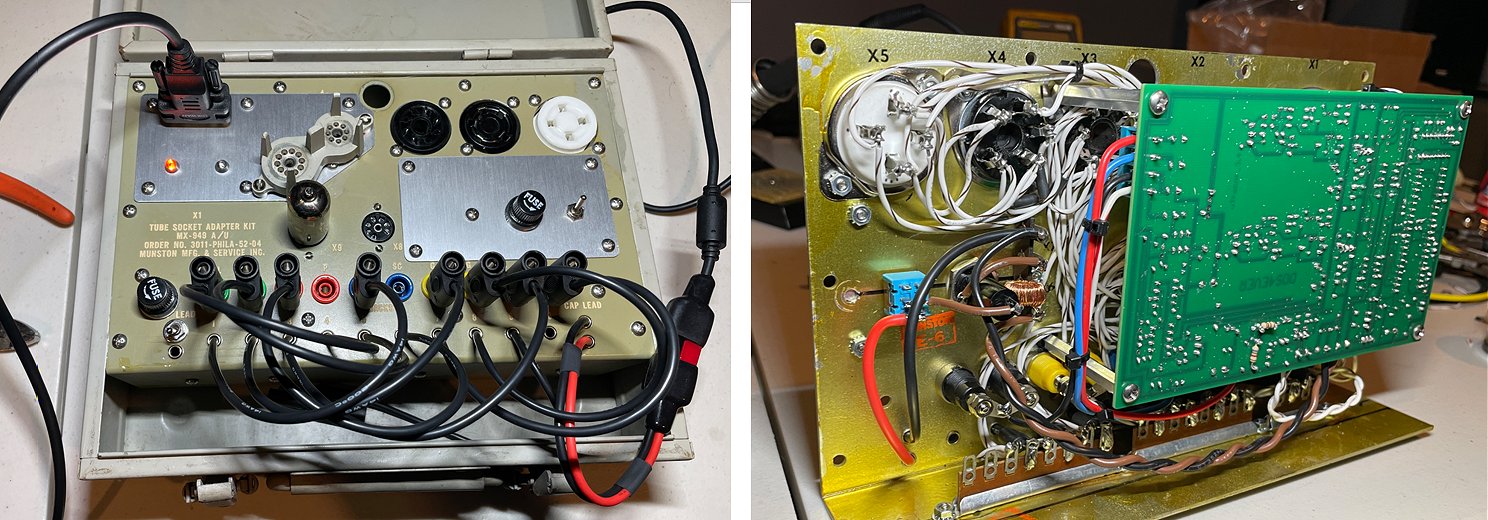
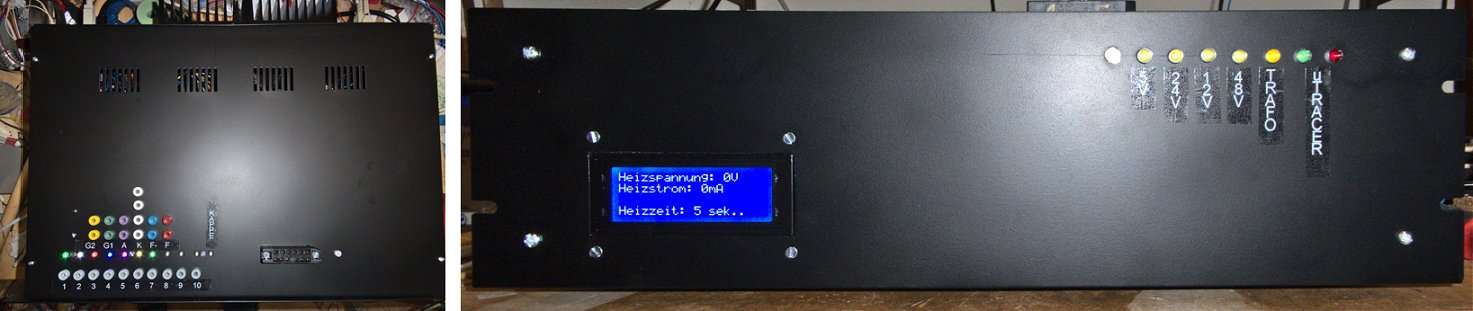
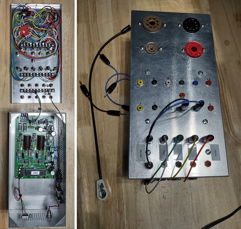
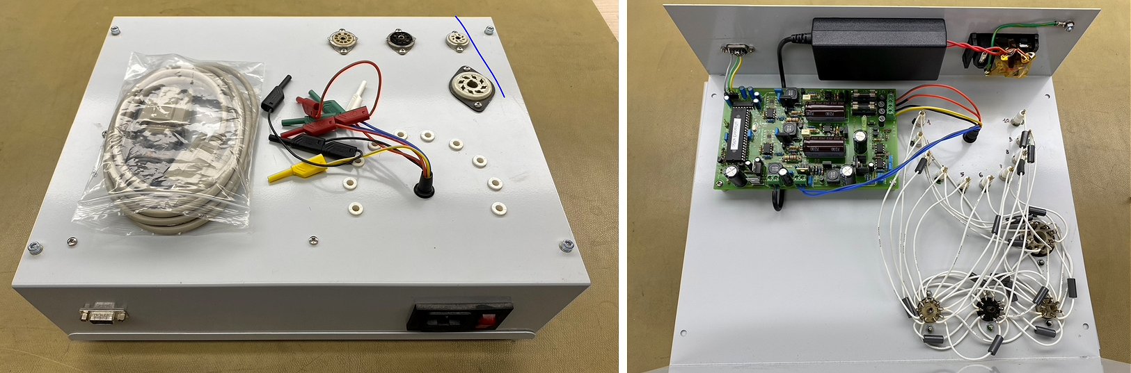
19th of May 2023 Martin sent me a few pictures of his enormous uTracer! Can you find the uTracer PCB?
Hello Ronald,
Originally I just wanted to build a suitable heating energy source for my already existing µTracer (built autumn 2019).
However, as I needed a larger enclosure than originally planned, I decided to order another µTracer 3+.
The housing is a 19" sheet steel housing with 3HE.
Since yesterday, the µTracer has been installed and in operation.
The attached picture 'Front.jpg' shows the finished unit from the front.
Inside are these assemblies:
- The µTracer itself
- A diode/rectifier measuring circuit
- 1 each heating current and heating voltage regulator
- A test circuit for checking the tubes for electrode connections
- Switching power supply units for the voltage supply of the individual assemblies.
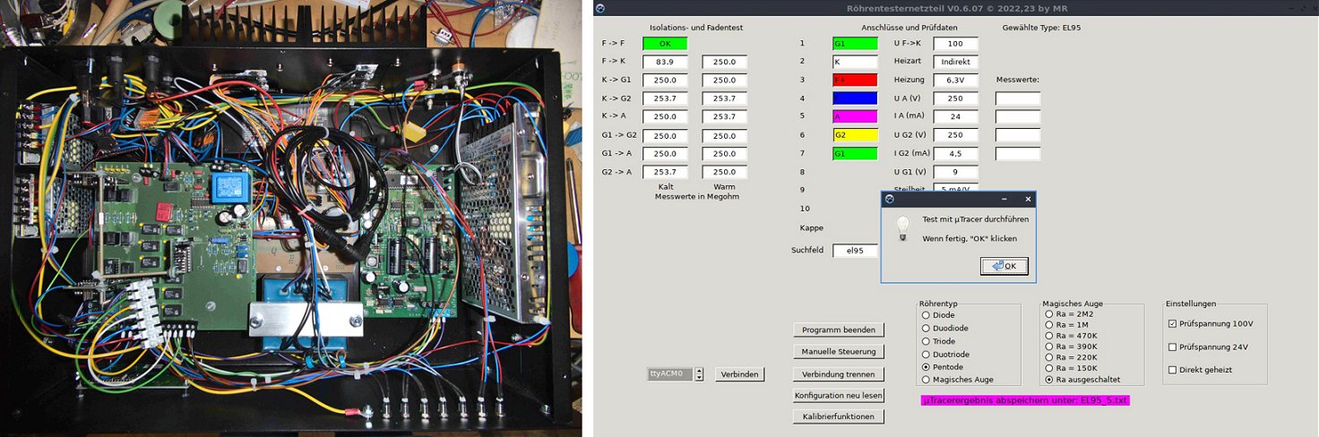
The pictures shows the construction:
Left side panel: Auxiliary power supplies, 12V for the relays and 5V for the NEOPIXELs.
Upper left PCB:
- Change-over relay for separating the µTracer from the electrode test circuitry
- Switching to test magic eyes, G2 (screen) is then connected to the boost converter Vs, anode to the boost converter Va.
Anode resistors for the control triode of the magic eyes are also connected in the anode line.
- Test voltage generation for the electrode test (24V/100V switchable)
- Reading back the leakage current as well as the test voltages with a PCF8591
- The electrode test circuit and the other relays are controlled by 3 driver-PCBs, each with 1 PCF8574 and ULN2803.
The I˛C bus is galvanically isolated from the control circuit.
Lower left PCB:
- One AC/DC module each 12V@0.9A and 48V@0.9A for power supply
- Linear regulated power supply 0 - 40V max, 0.2A for diode and rectifier testing
- Galvanically separated setpoint generation for the heating current and heating voltage controller.
- Change-over relay for switching between heating current and heating voltage.
- Relay matrix for diode and rectifier testing.
- An ARDUINO NANO-EVERY for controlling all functions as well as for setpoint output to the heating controllers by means of PWM, galvanically isolated via optocouplers and isolated DC/DC converters.
Middle from top to bottom:
- Laptop power supply for the µTracer
- PCB with the control electronics for the heating current and heating voltage regulator
- Transformer for the heating current regulator
Right:
- The µTracer
Right side panel: Switching power supply 24V@4.2A for the heating voltage regulator
Since I have some radios from the 1930s and also want to test tubes from the current series (e.g. U or P series), I use external power supplies.
Heating voltages: 0 - 12.6V max. 4A
Heating current: 0 - 300mA max. approx. 65V (approx. 105V at 50mA for the V-series)
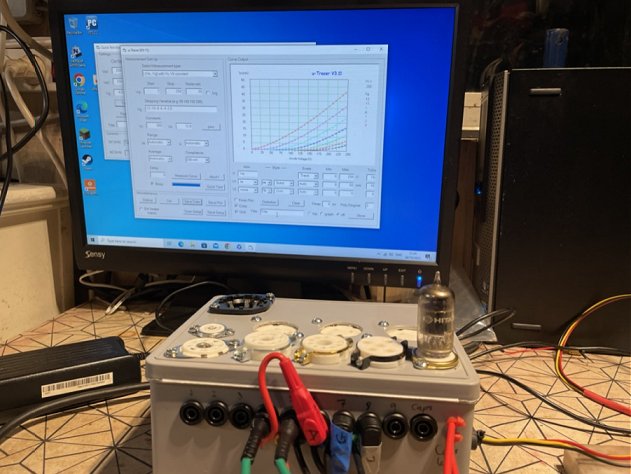
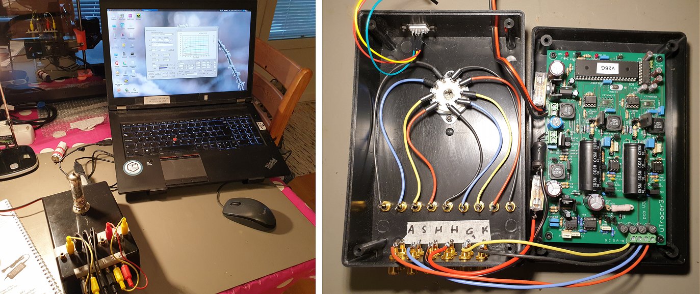
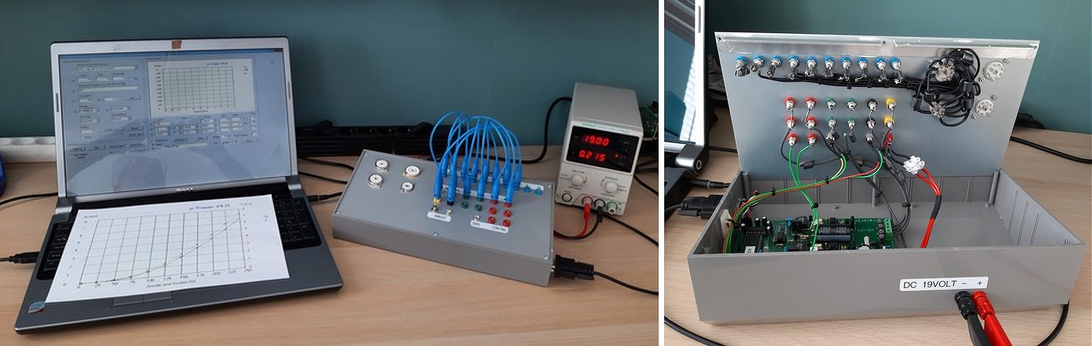
The image shows a screenshot of my control software (written with LAZARUS).
Above left, the results of the electrode test with the insulation resistances determined in megohms.
The test data of the selected tube (here an EL95) are displayed in the centre of the screen.
I get the data from a CSV file, which is then read column by column.
However, manual operation is also possible for types not included in the table.
On the top of the unit I indicate the cable colour to be plugged in with a total of 11 NEOPIXEL.
The connector to the right of the patch panel accepts the socket adapters.
In a further step, I would like to integrate the Quicktest routine with the commands described on your homepage into my control software.
But now that spring is hopefully starting, the realisation will certainly take until autumn or winter.
It's still quite cool here in south-west Germany!
Best regards from Germany
Martin
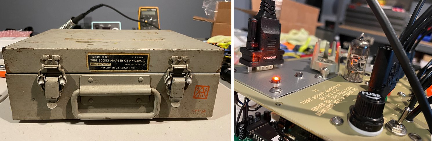
25th of April 2023 Have a look at Ray’s amazing amplifiers (and whisky collection)! In the future hopefully even better sounding thanks to his uTracer.
HI Ronald,
I was able to finish stuffing the board on Sunday as well as full calibration. I had no issues at all. Now onto the chassis. I attached a couple pics of an old military tube tester adapter that may be a good candidate after some socket changes and rewiring. Not sure if it's deep enough though. I like repurposing old gear like that when I can. I have a couple other military test equipment chassis that could also work, but the adapter was kind of "ready made" for this, so I hope I can make it work.
Question about PS and calibration? I calibrated with my CC,CV bench supply, but could only get 18.98 volts out of it. Will the calibration offsets track with input voltage changes, or do I need to re-calibrate if the laptop supply I have is slightly higher voltage?
I also attached a couple more pics of my latest SET amp inside and out, as well as a test amp chassis and PS that I use to test circuit ideas. It has all busbar connections for quick component changes, and removable saddles to change xfmrs.
I will update again when I have it in a chassis.
Regards,
RayL.
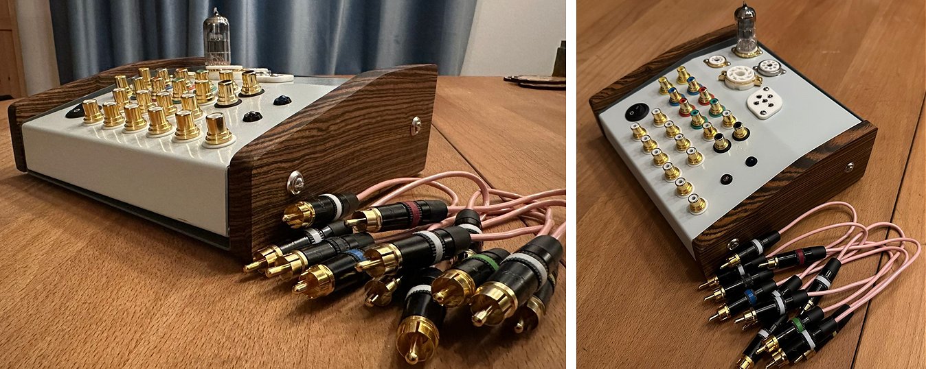
23rd of April 2023 Greg sent me a few pictures of his amazing uTracer (with rotary selectors)!
Hi Ronald,
Since everyone is showing off their build, I thought it’s time to share mine. Case is black walnut.
I do have a question however, how are people testing 6U5 tubes to show the function of the eye?
Cheers,
Greg Moore
14th of April 2023 Simon sent me a few pictures of his very neat uTracer!
Hallo Ronald,
Hier mal die ersten Bilder meines utracer3+
Die Änderung des neg. Power supply ist auch gemacht.
Bis jetzt läuft alles prima.
Grüsse aus der Schweiz
Simon
12th of April 2023 Way sent me a picture of his fine uTracer and an enthusiastic testimonial!
Hello Ronald,
I hope this communication finds you well. I made a couple of your suggested modifications for the grid voltage, as well as increasing the maximum current capability, and plopped it in a rather prosaic enclosure. I’ve thoroughly enjoyed using the uTracer 3+ over the last 6 weeks; it has been very entertaining being able to compare the quantitative measurements (especially with dual triodes displaying dissimilar I/V curves) and actually hearing differences in my amplifier designs (e.g. for cathode followers and cathodyne phase inverters, “rolling” different dual triodes based on the dissimilarity of their sections to “tune” them to higher gain vs. lower gain input channels, etc.). It has also been fun to match all the power tubes I have lying around. I am looking forward to using Derk’s Extract Model for all the tubes I have without existing LTSpice models.
Thank you again for creating such a wonderfully well thought out and useful instrument. Now that I have had more time to digest your lab notes blog, I especially have enjoyed seeing how you tackled all the challenges along the way. Kudos.
Sincerely,
Way
5th of April 2023 Joris sent me a few pictures and a testimonial of his magnificent uTracer!
Hi Ronald,
During the lunch breaks at work I had a nice little project for the past months. Assembly was a breeze (I must confess I did not follow the partial assembly, did it all at once) and it worked first time. After some testing and calibrating it was time for an enclosure. I wanted to make it compact and portable and at the same time make it with stuff I already had laying around. The enclosure is from an old GPS receiver development kit, the meters are from a TV pattern generator and the tube sockets from an LCR bridge. I opted for 4mm sockets to connect the tube to the tester, since I have a lot of 4mm banana plugs at hand. The 2mm version would have been nice as well, but I would have had to buy all. I included a small heater supply section based around a simple switching regulator. The potentiometers to set the voltage and current were wired to the front panel and I added the voltage and current meter. The accuracy of these is not great, but it gives an indication... I added a preset 6,3V switch as I use that most of the time. As I had a broken PCB with a USB C to serial converter on board I figured it would be a nice modern addition to include it, so I cut that piece off and added it to the rear panel. To keep the retro feel I used the Rotex to make labels. In the pictures I had not numbered the sockets for the tube sockets.
After the first assembly the uTracer broke unfortunately :) Since I made it so compact the pins protruding from the PCB punctured the insulation of the tube sockets' wiring. Ronald quickly shipped a repair kit, what a service! The second time it failed was the BD138 transistor in the negative supply. I replaced it with a BD140 and it has been fine ever since. (I had the ringing suppressor resistors installed from the beginning) When it broke I noticed that the voltage regulators got quite hot. Moving them to the enclosure eliminated any heating. So far I have tested a lot of my tubes and was able to rule out some faulty ones. It really is a nice piece of equipment to have!
I highly recommend building this. It is really nice to build something and not having to design everything yourself. You'll always arrive at a useful working product in the end!
Kind regards
Joris
26th of March 2023 Sylvain sent me a picture of his own version of the uTracer3 PCB including some of the extensions!
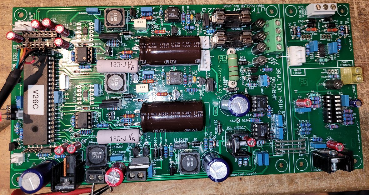
Hi. I know you like to see different versions of your great project.
Here my own version 3+ PCB. I redraw all the pcb, incorporated all the revisions, mods, and added a side section with the Grid Loop and Cap forming options.
So far the main section is all working perfectly.
Thanks again for sharing such great project.
Sylvain
22nd of March 2023 Jose from Argentine sent me some pictures of his uTracer that he completely recreated from stuff he had available! Fantastic! I take my hat off!
Dear Ronald :
My name is Jose Luis Fernandez from Buenos Aires Argentina. I have been reading the contents of your website , Dos4ever , since around 2020. In fact , I found it by luck during the pandemy. I am an enthusiast of both DOS and old technology as vacuum tubes and the like. In my youth years ( I am 62 now) , I began experimenting in radio and electronics and at sixteen , became a licensed amateur radio operator . Tubes where common in those days, specially in amateur radio, so I think someway I developed a deep interest in tube technology ,that is alive even today. Some of my friends think I am crazy because of this, but no problem , fortunately I was able to find your website as well as another ones with people as enthusiast as myself ( or as crazy as me!....who knows) . Now , with world wide web , we have access to a huge amount of literature about tube technology, that unfortunately I did not have when I was at school.
Since 1987, I became an electronics engineer ,and until now I am working in the factory automation field. specially in power electronics ( induction heating , drives, ect) usually trying to solve the problems that no one wants to do, because is not good business, old PLC systems and industrial computers and machines based for example in DOS not to mention induction heating and soldering using high power tube oscillators I was asked to design , several years ago , a numerical controlled machine for making keys , using servomotors (Indramat) for the various operations. I implemented it with a PC running VB 1.0 that is DOS based , not very beautiful Graphics but extremely stable . In fact , this machine ( we finally made two of them) is working since 2006 without any failure related to the PC or DOS program. It has a solid state disk , but the system never hanged up since it was put in operation.
This introduction is only to try to explain who I am , and to say that , I really fit your description of one of your crazy readers! But I am proud of it!. When I found the project of the Utracer in your site , it was shocking, finally an idea of how to make an instrument to see the actual curves of the tubes that until today were only available in those old manuals. Something extremely well designed, in my opinion and very well documented. As your design progressed I became more interested in making one for my own lab.
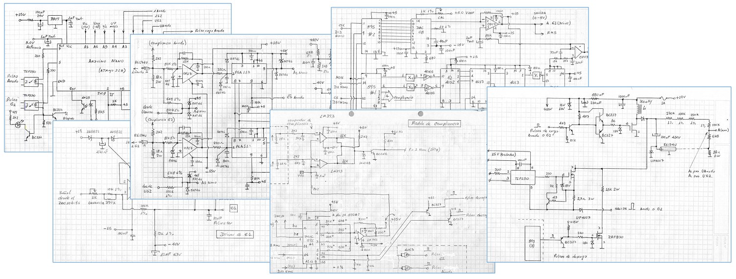
When finally you offered it as a kit, that was the opportunity to do it, but unfortunately, some health problems and money related ones, appeared. It was not possible to afford it. So I decided to try to implement another version of the hardware, but using your nice software.It was a personal challenge. It was necessary to build it section by section, following in general your ideas, but adapting them to the parts and processor that I had available. I have used other type of switch , borrowed from the industrial power world and another type of power supply. With both, there were many problems related to noise ,difficult to solve ,but very interesting to study in detail. In the diagrams, I apologize for the poor quality, handmade, ( very in the line of Bob Pease drawings) you will see some details, for example the power for the switches is taken from an isolation transformer( with low capacity) from the power transformer to decrease the capacitive coupling to the former, without it , high frequency energy appeared just over the measurement pulse.
All the parts , except the PGA´s and some precision resistors, came from junk, old TV sets, old instruments and discarded industrial equipment. I have used extensively material from Phillips because it was and is now very popular in our country. Phillips used to have in Argentina production facilities for tubes and transistors ( with the FAPESA name) so became very popular at the time ( early 70´s) The result is very good for me, it was beautiful to see it tracing caracteristics of my old tubes , and of course , it has the Utracer name because I think that IT IS your design!. I only adapted it to a different processor. I added the name AR because it was based in an Arduino Nano ( it has 8 analog inputs available) . I used several ones for industrial projects and have one still as a spare.
It took quite a lot of time to design and build the several parts , but finally is nearly finished and ready to be used. So I decided that you have to know about it , you have one more of your Utracer´s in this part of the world. I am sending you several pictures about the appearance , the schematics of the main sections and specially the result of the measurement of an ECL80 , in order that you can tell me your opinion about how it is working ( If you agree and have the time, of course). I would appreciate it a lot.
I have a profound debt of gratitude with you , and have to say that it was a pleasure ( as is still now) reading about your projects , histories about Phillips Research , and to see some pictures of your daily life and beautiful family. Working on this project have been a healing process, for myself. I hope , in the future ,I could became one of your customers Ronald.( Maybe with the BIG utracer) In the meanwhile , I will continue reading your web pages , and enjoying your ideas and comments. The orange colour in the interconnection cables for the elctrodes are , of course in your honour.
Finally an apology , for my English, it is not my native language so , is not easy for me to write these words . Thank you very much Ronald !!, and if any time, you need something , from this remote part of the world, please do not hesitate to ask me.
Sincerely : Jose
16th of March 2023 Mike finished his very nice uTracer!
I have now finished building my uTracer 3. I am attaching a couple of photos showing its internal construction and the end result. You will notice that I have opted to layout the 9 pin sockets for the patch panel in a circle. These are numbered 1 - 9 clockwise so that they are how I see a valve base from inside a chassis - and the same as many data sheets which show the pin connections from the underside of the valve. In the second photo you see one of my first tests - an EL84. I only have the octal and noval bases for now as these are pretty much the only types of valve base used in guitar amplifiers. If I ever want more, I could build an extension box just containing valve sockets and patch across to it. I have yet to add labels to the box, but will get around to that soon.
I am beginning to see the enormous potential of this valve tester, so my next task is to understand the full range of it's capabilities! Thanks for bringing this kit to us, and for your very clear instructions.
Mike
8th of March 2023 Bjřrner from Norway sent me a few pictures and a report of his fantastic uTracer and the amazing additions that he made to it!
Hi,
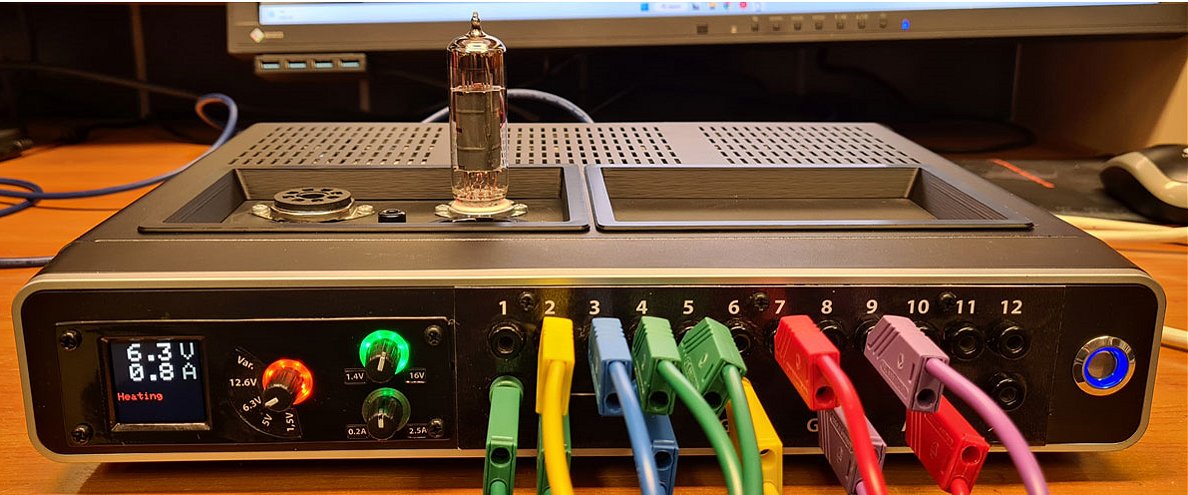
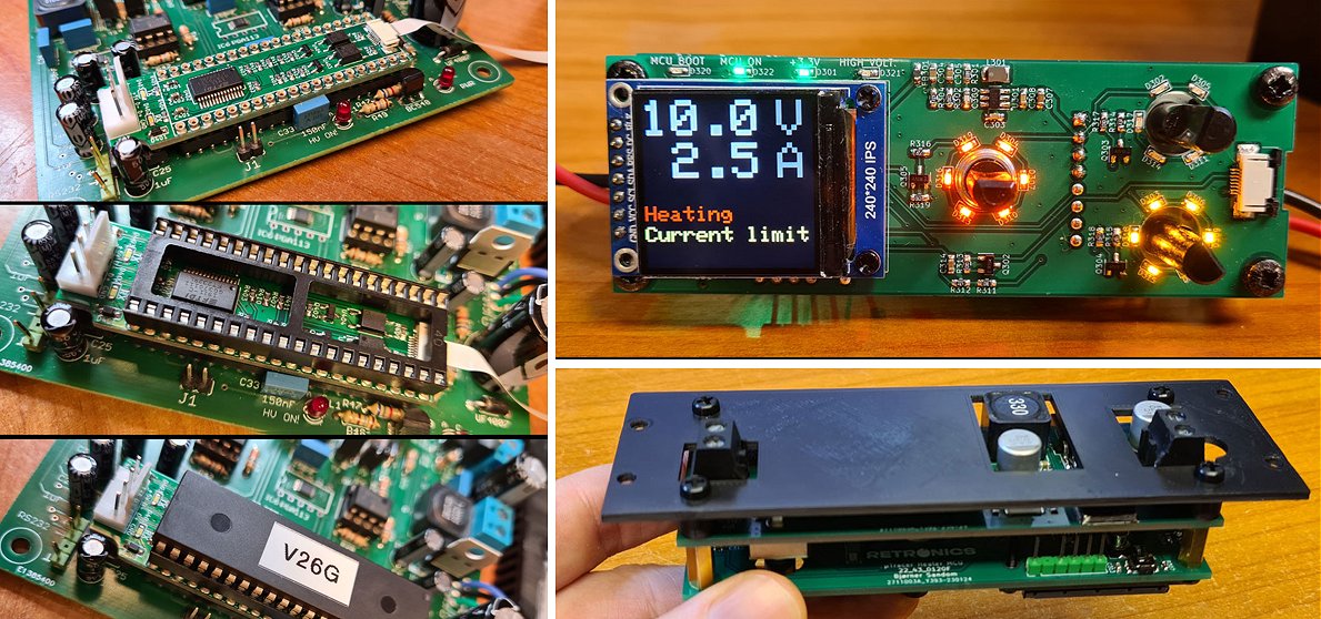
Thought I’d share a few pictures and description of my µTracer3+ implementation, for the testimonials page. It took me a while to build this thing, since I decided to make some addons/modifications, but now it’s up and running, and it works really well. One addon is a USB adapter board that can be installed between the PIC and its DIP40 socket, to eliminate the need for an adapter cable. I also made a custom switched regulator and measurement module for heater voltage/current, with selectable voltages of 1.5, 5, 6.3 and 12V, plus continuously variable voltage between 1.4 and 16V. This module also has an adjustable current limit up to 2.5A, which gives the filaments a soft start. Though being a separate module, the heater PSU output can be turned on and off from the µTracer software. The project is built in a reused enclosure from a scrapped TV-decoder. A short YouTube video shows the unit being used in practice: https://www.youtube.com/watch?v=7Mg959vXJqE. I also recently started a blog https://retronics.no, and detailed description about construction, addons, and schematics, plus a review of the µTracer can be found there. All the related blog posts are linked from the YouTube video. If someone wants to build the USB adapter or the heater PSU module themselves, I will gladly share Gerber files for PCB manufacturing.
Best regards,
Bjřrner
Norway
5th of March 2023 Scott reported his uTracer finished!
Hello Ronald and Marie-José,
I ordered my uTracer 3+ kit back in 2016 as you can probably see by the previous email. Wow, time is a fickle friend. Life kind of got in the way, and since then I've retired and moved back to my home state of Florida.
Finally built the tester, works great! The build manual is fantastic, all of my tests results along the way just as described. Thank you very much for a great device.
All the best,
Scott
www.naturecoastelectronics.com
23rd of February 2023 Way Yin finished his uTracer and he wrote me a very enthusiastic review!
Dear Ronald and Marie-José,
I just completed building, testing and calibration of your wonderful uTracer3+ kit.
After a slow start on my part (not being a Windows user, not being really familiar with some of the cool components on a PCB, and generally being an idiot) I've completed buildout, testing and calibration of the board.
I wanted to convey how much I truly appreciate the extensive work and great care you have devoted to creating such an incredible package that a hobbyist like myself can enjoy. Everything, from the meticulous and well segregated design of the PCB, the logical layout and construction with testing of each section, the excellent manual, the clever GUI, the thoughtful pre-population of the board with hard-to-mount components, and the precise and logical selection and packaging of all components, made this one of the most enjoyable projects in recent memory - and reminds me of the joy I had as a child building and flying model airplanes and rockets. The attention to detail on your part made for a flawless and uneventful buildout without a single hitch or moment of frustration.
I look forward to wiring my enclosure and enjoying your uTracer3+. The examples you have posted of other builds has been a great idea generator. Thank you again.
Wishing you the best,
Way Yin
8th of February 2023 Kari from Finland finished his simple but effective uTracer
I'm glad to report that I have now (finally) built my uTracer3+
With your excellent and detailed instructions the build process was very easy and enjoyable. Everything worked first time. ( Except for a stupid mistake I made all by myself )
Here is a picture of the tester before buttoning up the case.
For the first test subject I grabbed a dusty old EL84 pentode that once served as an audio amplifier for a radio from the 50's. No big loss if it blows up..
Not only did the tube not blow up but Quick Test revealed that it is in fact in good condition!
This picture shows measuring the curves from the same tube. I'm running the gui under Wine emulation on my Ubuntu 18.04 Linux computer.
Thank you very much for providing this great kit for us tube-lovers!
Wishing you all the best in the future.
Kari
4th of February 2023 Ryuji from Japan Finished his very fine uTracer !
2nd of February 2023 Hans from Holland sent me a few pictures of his beautiful uTracer!
Dag Marie-José en Ronald,
Hierbij twee foto’s van de uTrace3. Bij de bouw vond ik het telkens toch spannend of de tussentijdse testen volgens de uitstekende handleiding klopten. Alles ging naar verwachting. Van een oude plank en een aluminiumplaat die ik nog had liggen heb ik de ombouw gemaakt. Inmiddels heb ik diverse buizen doorgemeten waaronder 300B’s en KT88’s. Mooi om te zien dat 1 van die laatste buizen beduidend slechtere resultaten gaf dan de rest. Een verklaring voor het probleem bij de bias-instelling. Ik gebruik overigens een externe voeding voor de gloeispanning, dat geeft ook bij de wat minder dorstige buizen de beste resultaten. Ik heb de uTracer aangesloten op een laptop die ik eigenlijk al had afgeschreven en ook op een nieuwere computer via een usb aansluiting. Beide systemen werken perfect. Bedankt voor de mooie bouwset, de uitgebreide handleiding en de verzorgde site waarvan ik veel geleerd heb.
Met vriendelijke groeten,
Hans
14th of January 2023 Mario sent me a picture of his finished uTracer !

Hi Marie-José & Roland.
Thank you for your best new year wishes. First of all i'd like to wish you a very good year 2023 as well. Hope you had a good, loud transition with your family and friends.
A long time ago I ordered one uTracer3. The final assembly was pretty easy due to your fantastic guideline. Even the usage of the uTracer3 is pretty easy.
Thanks again.
As of now the uTracer3 helps my to check all the tubes from my tubes seller's all over the word before using the tubes in my devices. Of cause all of the tube seller's promising a perfect quality and a tight matching. The reality differs extremely. However. Your uTracer3 is a good value for money tool to separate the tubes as well as the tube seller's. Nowadays tubes are extremely expensive. So the uTracer3 helps me to save the electric devices and finally uTracer3 saves my money. Too ugly tubes are not used and will returned to the tube seller's.
I am happy, thank you and go on with your activities.
Greetings from Germany
Mario
3rd of January 2023 Paul sent me a few pictures of his very nice uTracer!
Hi Ronald,
Per your request, I'm attaching a couple of pictures of my version of the uTracer3+. This version uses 3d printed "personality modules" that plug into the unit--each one for a different tube. Since my primary use is for testing and sorting specific tubes, it seemed more robust to use these modules rather than patch cords or switches for connecting the tester to the tube elements. Any time I need a new module I simply 3d print a new box, and make the necessary connections on a small PCB that goes inside.
Best regards,
26th of December 2022 Auke sent me some pictures and an extensive account of his “three headed beast”!
Hi Ronald,
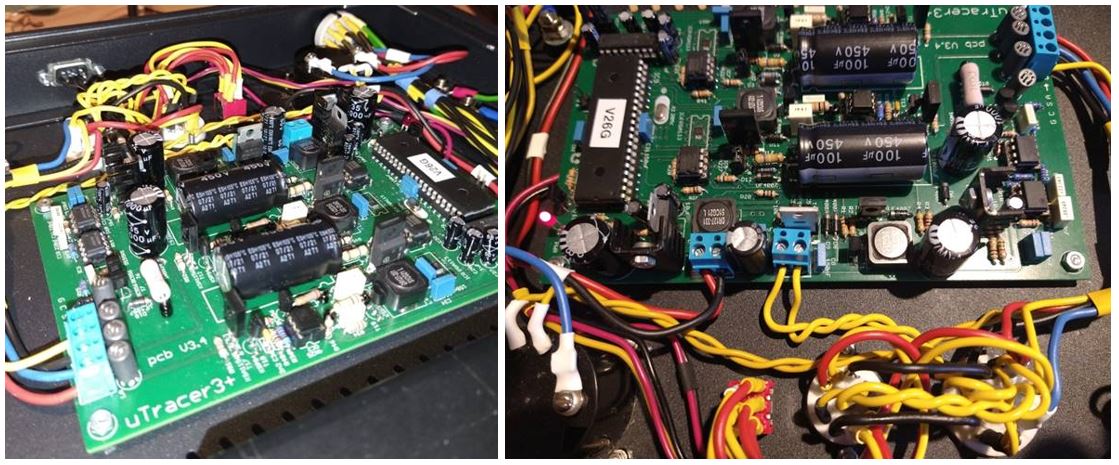
Hereby my version of the uTracer3+.
I think you might call it the uTracert3+ plus2
Now please keep in mind that my “three headed monster” is still “under construction”, work in rogress, It will change a lot… and is far from done…
First of my compliments to you.
The uTracer3+ is very easy to build, with a good step by step build and testing manual.
The KIT has all components, very well labeled and packed.
Although It took me a few months to build (due to the lack of time I could spend) the actual building time was less than 24 hours including calibration.
My needs from day to day repairing amps.
What I have done in my build is somewhat different than usual. In fact, it became a small 19 inch three headed beast! Tailored to my insights and needs.
My needs are just the most common tubes like the EL34, 6L6, ECC XX and sorts…
My main field of use is Guitar Amplification tubes. So, I set up with a fully wired 8 pins socket and a parallel wired 9 pin socket.
This left me with a problem being EL84 tubes… Luckily there are adapters that fit the 8 pin socket… Problem solved.
As time passes, I might feel the need to create some other adapters.
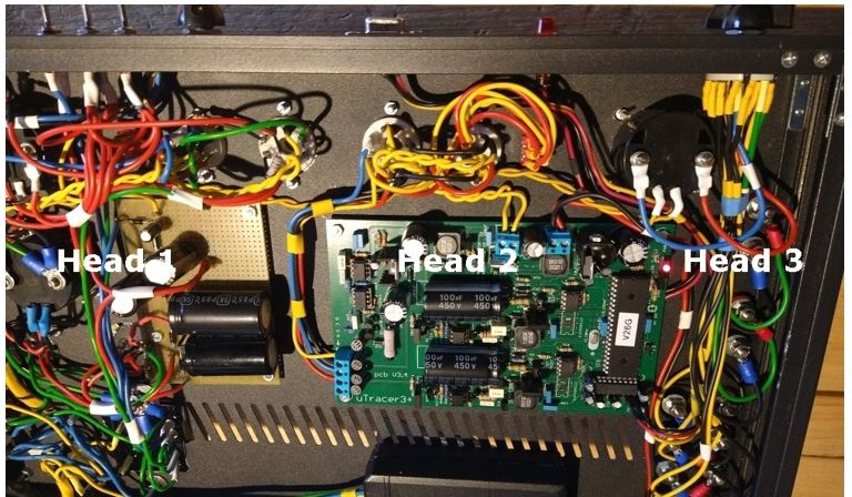
To my three head beast build, from left to right..
The 1st “head” is a simple DIY Emission tester, complete with Gas/Gasless test and tube short indicator and a measuring range from 90 volt up to 275 volts Very handy for quick testing of tubes of any age. This tester has no connection with the uTracer3+. It is fully analog, and results vary a bit with source feed wall outlet varying. It uses two supply transformers. One transformer 2x 6,3 volt for heating and illumination, and a 2 x 15 volts in series to create switchable 90 up to 275 volts using voltage pumps and minus 30 volt for bias. I’m planning for a digital voltmeter connection to be added to make it a bit more accurate.
The 2de “head” of the Beast is the uTracer3+. All hard wired, nothing special there. The only thing I changed was the High Voltage “on” Led placement. I mounted the LED in a small Neon Indicator fitting and mounted it on the front panel.
During mounting of the PCB, I probably bended the PCB a bit. One of the HSP Coils become loose and caused the Software to Hang during testing and getting no results. I broke my head around that problem and in the end, I contacted Ronald and he very quickly diagnosed the problem. Many thanks for that. I just did not see what was going on…and you did with all the knowledge you have on your brainchild.
As one can make up from the pictures, I used the “old school” heating wire twist mounting. Not only for the tubes but also for the useless Analog panel meter illumination. I know for the uTracer heating it has no extra value, but I might go for the external heating option. Then it will be a good idea to have the twist heating wires (and ground balance them) to eliminate hum and magnetic field dispersion. Since this 3 headed beast does not uses high gain amplification it is of no further use than easy recognizing heater wires. I used a slightly modified LENOVO 65 Watt laptop supply. It stripped it from its mains connector and wired the mains straight in. And I replaced the low voltage output lead for regular wires used throughout this build. This saved me lots of space inside my 19 inch housing. It is mounted using NANO tape on two sides.. Great stuff.
The 3th “head” is a fully passive “final” testing option. When an amp receives a new set off well matched tubes, I made it an issue to check if “surrounding components” don’t throw the set out of balance.. This is usually done by scoop and sinewave measurements at fairly high power, but I found that this not always tells the whole story. The 3rd head is capable of measuring mA per tube in the amp itself using extension adapters. A well matched set should deliver exact equal measurements per tube just running idle… If not… there is more work to do! It uses a 50 mA analog panel meter and it will get DVM connections options. It also can measure the idle ma balance of the phase shifter tube or any other double triode.
This concludes my uTracer3+ plus 2 build.
All what is left to do is getting the user manual printed and getting the hang of all measurements possible with the uTracer 3+
Thank you Ronald for providing such a great KIT.
Kind regards to you and your family
Auke Dost
18th of December 2022 Francisco used the casing of an old AVO CT160 to make a fantastic uTracer!

Greetings from Spain,
With almost 3 years of delay I present my U-tracer 3, it is working perfectly since its assembly in 2020, (I think I bought it in 2019), but I took its construction slowly, now I am going to start the assembly of the U-tracer 6 version which I purchased from you a few months ago. I have used the remains of a magnificent Avo ct160 for the connection board (the Avo was rescued from a metal crusher about to be totally swallowed) fortunately I was able to recover many parts, although it was impossible to fully recover it, Avo ct160 and U -tracer are made for each other, in fact I am using Avo's configuration data for U-tracer. U-tracer 6 will surely be assembled using the board and cards from a Funke W19.
Greetings again and thanks for your great work at U-tracer.
Paco Perez.
Saludos desde Espańa,
Con casi 3 ańos de demora presento mi U-tracer 3, está funcionando perfectamente desde su montaje en 2020, ( creo que lo compré en 2019), pero tomé su construcción lentamente, ahora voy a empezar el montaje de la versión U-tracer 6 que adquirí a ustedes hace unos meses. He aprovechado los restos de un magnífico Avo ct160 para el tablero de conexiones ( el Avo fue rescatado de una trituradora de metales a punto de ser engullido totalmente) afortunadamente me fue posible recuperar bastantes partes, aunque fue imposible su recuperación total, Avo ct160 y U-tracer están hechos uno para el otro, de hecho estoy usando los datos de configuración de Avo para U-tracer. U-tracer 6 será montado seguramente usando el tablero y las tarjetas de un Funke W19.
Saludos de nuevo y gracias por vuestro gran trabajo en U-tracer,
Paco Pérez.
13th of November 2022 Alan reported his fine uTracer3+ up and running!
Hi Marie-José,
Received the utracer3+, assembled it, and all is working great! Thank you and Ronald for this wonderful project.
Alan
30th of October 2022 Have a look at Wouter’s amazing uTracer3+!
Goedemiddag Ronald en Marie-José,
I promised to share the final result of my uTracer3+, which i have been using for over a year now.
The build went without trouble, thanks to the great manual.
I mainly use ecc82 and 83’s, so i made a dedicated section.
For housing i chose a petanque-case with active cooling.
My girlfriend has a cutting-plotter, so designing the front panel decals was fun, cheap and easy.
Ronald, i still don’t get how you came up with this fantastic device, but i’m glad you did! Thanks!
Kind Regards,
Wouter Freeman
9th of October 2022 Auke from Holland reports his uTracer3+ working!
Dag Ronald en Marie-José,
Ik wil jullie even laten weten dat er een nieuwe uTracer 3+ het gloeiende levenslicht heeft gezien! Compliment voor de super bouw beschrijving. Klopt van A tot Z.
De test en calibratie moet je even inkomen .. soms miste ik even de haak en lijn waar ik moest kijken voor de juiste waardes maar het is goed gekomen.
Binnenkort stuur ik jullie wat foto's van de voortgang en het uiteindelijke resultaat.
Groet en dank voor dit mooie product.
Groet,
Auke
10th of september 2022 Norbert from Austria realized a beautiful uTracer3+!
Dear Ronald,
I hope this email finds you and your family well.
I finally and happily can report that I finished my uTracer 3+ build a week ago. :-)
Thank you for all your time, expertise and efforts to develop such a cool tube curve tracer & tester and offer it as kit version to the interested DIY community.
After I ordered and built a uTracer 3+ kit end 2015 / early 2016 - the finished board has worked fine from spring 2016 as your construction manual is excellent - it took me until end Aug. 2022 (including a long break due to my work load in my job for some of these years) to complete my uTracer build. To explain this, to select and build a proper case and finish the mechanical work is always the most time consuming and hardest part for me, especially when the job is demanding. So, finally after my retirement on June 1, 2022, there was the time to finish my build. And it worked out :-)
Enclosed please find some photos of my completed uTracer 3+. A nice badge stating something like "uTracer 3+ by Ronald Dekker (400V version)" has still to be made and will be put on the uTracer top plate in the right upper corner. :-)
For DHT triode power tubes (45 and 2A3 in my case) I use an external heater (ie a laboratory DC power supply, I bought some years ago).
Thank you once again for bringing the uTracer project to the DIY community! :-)
Best wishes,
Norbert
8th of July 2022 Preben from Denmark (OZ1PDE) built a beautiful uTracer for the Sřnderjyllands Radiomuseum
16th of July 2022 Preben sent me an update of the construction
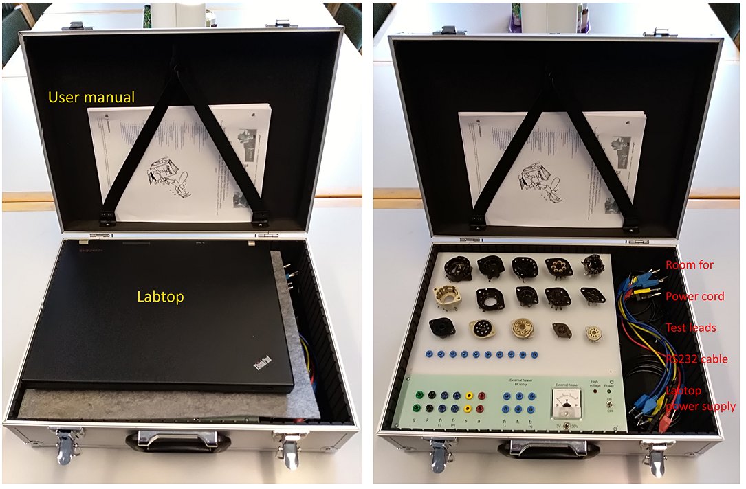
Hi Ronald
Thank you for posting pictures of our edition of the uTester on your website, and special thanks for your reference to the Radiomuseums website.
Our version of the uTester is still under construction, so I would like to attach some comments to the pictures and have also sent a few new pictures.
The idea of our uTester is to have everything you need in one suitcase. 15 different tube sockets are mounted on the top plate. In the compartment on the right side, the power cord and RS232 cable come out, so there is no need for connectors on the outside of the suitcase. At the same time, it is used for storing test leads and power supply for the laptop. In the lid, space has been made for the user manual. In addition, there is room for the laptop.
Best regards
Preben
26th of June 2022 Have a look at Peter’s magnificent uTracer!
24th of June 2022 Randy send me a few pictures of his finished “military style” uTracer!
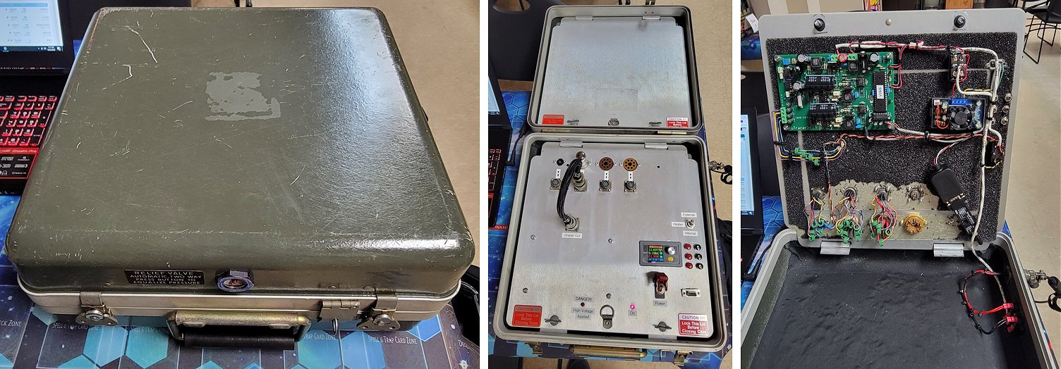
Greetings!
I've spent quite a bit of time over the last few weeks on finishing up my Utracer build.
I chose an old US military case...pre Pelican style. It perfectly matched the "theme" I was shooting for. I tried my best to make it look at home with other 1960's-1970's military tube testers.
For the tube wiring portion, I went with cannon plug cables. Each socket has designated cables to use according to the tube pinout. I chose this method over the open jumpers for a couple different reasons. No accidental touching high voltage test points and a cleaner look. As much as I love rotary switches, the associated wiring is rather difficult, time consuming, and not as clean looking. This also allows me endless expansion capabilities, and I have already 3D printed some external socket enclosures.
For communication, I went the Bluetooth transceiver route. Model is a Parani SD1000. It's a direct serial RS232 to Bluetooth adapter. That way I don't have to drag around a serial to USB adapter and a serial cable. So far it has worked flawlessly with 2 laptops, a 10" Windows tablet, my Android based phone(with the app), and a 10" Android based tablet. My goal is to mount the 10" Windows tablet in the lid of the case, so it can truly be an all in one solution.
This was quite a fun project! Thank you for designing the Utracer and making it available to the masses.
Feel free to post my photos if you would like.
Randy.
20th of June 2022 François sent me a few pictures of his fine uTracer3 !
By the way,
I never took the time to send you pictures the first version.
Nothing fancy, just plug the AC and a serial/usb adapter and you’re tracing.
It works flawlessly since I built it. All cables are silicone for security.
Thanks again to both of you for your dedication.
Best Regards,
François
14th of May 2022 Theo sent me a few pictures of his fine uTracer (in Dutch)!
Hallo Ronald,
Bijgaand een update berichtje omtrent mijn uTracer.
Na de omissie bij hoofdstuk 8 is de verdere opbouw van de uTracer probleemloos verlopen. Hij werkt inmiddels naar tevredenheid en ik heb het geheel ingebouwd in een simpel kastje. Voeding wordt verzorgd door mijn labvoeding goed beveiligd en mooi stabiel. Ik heb vooralsnog een tweetal type buisvoeten (Noval 9p en mini 7p) aangesloten om de kans op oscillatie zo klein mogelijk te houden en heb besloten om, wanneer ik in de toekomst andere typen buisvoeten benodigd ben, deze onder te brengen in een separaat kastje van ook weer max. 2 stuks. Ik ben reuzeblij met m’n UTracer en beveel jouw briljante set dan ook in heel mijn kennissenkring aan!
In de bijlage zend ik je nog enige foto’s van m’n creatie.
Dank voor alle goede zorgen het snelle advies wat ik tijdens de bouw mocht ontvangen!
Fijn weekeinde toegewenst en groet ook aan Marie José.
Theo
8th of May 2022 Andre in Berlin shared a few snapshots of his finished uTracer!
1st of May 2022 Hartmut announces the birth of a new uTracer!
Hallo Marie-José en Ronald,
It`s finished.
Date of birth: 05/30/2022, weight: 3 kg, length: 28.50 cm
Thank you for your time developing the kit and for selling it at a more than fair price.
And above all, a big compliment for the really perfect assembly instructions, which also enable someone without much technical knowledge to assemble the device.
I still have to practice measuring myself. So I measured an old, used EL84 with 110% and immediately afterwards a new JJ Electronic EL84 bought from a specialist dealer with 51%. Of course it can be true. An EABC80, for example, seems to be a particular challenge in terms of measurement technology. since I have been working with tube technology for about three months, it could be possible, that I still have to learn a little. :-)
Hartelijke groet,
Hartmut
12th of February 2022 Dirk from Germany finished his uTracer3+ and is already planning a suitable housing for it!
Hello Marie-José, hello Ronald
the Kit ist build and testet. Everything seems to be fine. The construction manual is very well made!
The next step is to build the housing, I am still thinking about an upgrade of the heating and the sockets...
All the best
D.D.
2nd of February 2022 Hans-Jürgen from Austria sent me some pictures of his excellent uTracer!
Lieber Ronald,
ich habe vor einigen Jahren den uTracer gebaut und vor Kurzem einige Funkamateur-Freunde animieren können, dieses Gerät ebenfalls zu bauen. Einige dieser Geräte funktionieren schon erfolgreich. Anbei einige Fotos meines Gerätes zur freien Verfügung.
Liebe Grüße
27th of December 2021 Geri sent me a few pictures of his very fine uTracer!
Dag Ronald
Mijn uTracer 3+ is al een tijdje klaar en ik ben er dik tevreden mee. Ik heb er wel intern een separate voeding voor de print in gebouwd en twee gloeispanningsvoedingen van 6,3V en 4V. Dat zijn voor mij de meest voorkomende gloeispanningen en de overige kan ik eenvoudig extern invoeden. Dat zijn er zoveel, ook meer dan 19V voor U-(eind)buizen. Door voldoende ferrietkraaltjes in de bedrading naar de buisvoeten op te nemen, heb ik nooit last gehad van oscillaties. Ik heb ook eindelijk een goed USB-RS232 snoer op de kop kunnen tikken (van DSD-Tech type SH-RS232AUSB met FTDI chip DB9) en nu werkt de communicatie met de laptop ook probleemloos. Het enige wat ik nog wil toevoegen is een Volt en Ampčremetertje voor de gloeispanning en stroom, m.n. voor dat laatste. Ik heb gemerkt hoe prettig dat dat is als ik een externe gloeispanningsvoeding (met V-A meter) gebruik. Dat metertje loopt in bestelling. Ik stuur je wat foto’s van mijn uitvoering. Misschien kun je er wat mee.
Hartelijke groeten en een fijne jaarwisseling, Geri
15th of December 2021 Thomas sent me some pictures picture and an extensive testimonial because he is very pleased with his uTracer!
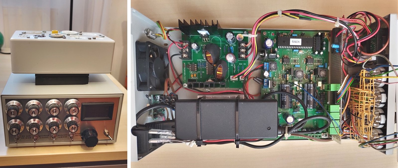
Dear Ronald,
When I started to clean my father’s storage, I found thousands of vacuum tubes. I remember well that my experience with this technology was limited to my teenage years and quicky phasing out the years following. But I started to investigate in this technology again and as well browsed for methods to verify the function of tubes. That was the time when I stumbled on night over your home page and after a few days and testing the software I decided to go for it to make myself a birthday present.
Thanks a lot for your excellent project µtracer3+! The kit was perfectly prepared and following the instructions it took me just like 5 hours to complete the main part. The time I spent after that was more something like ten-fold ??. In the following I present my interpretation of this great project.
The base case is a complete set intended for a laboratory power supply kit. The front is a simple aluminium plate I folded and fitted. On the top a 20pin connector interfaces to the socket adapter, currently only one adapter for post-war tubes is existing.
After browsing through discussion threads, FAQs and testimonials I set my personal goal to squeeze almost all ideas I found into my setup. The look into the inside shows that the gear is quite packed and there is not much space left. The fan including fan control on the left (back) side was already part of the case. Underneath the laptop power supply there is a second independent power supply which is providing the 15V for the auxiliary heating source – a combined step up / step down converter offering all ratings between 1.4V to 14V and 14V to 60V.
My personal goal was to go for a compact solution using rotary switches to assign the measurement ports to the pins.
As said before, the intention is to pack into as many use cases as possible. That is why I added an additional grid port “X” which function is dependent on the mode selector “M”. The first three modes connect “X” to “C”, “G” or “A”. However, the other three modes are foreseen for magic eye setup and influence both the “S” and the “X” port. I admit I did not test all modes yet.
The density on the front turned out as a special challenge and the third wiring attempt of the switching matrix succeed by utilizing 0.9mm coated copper wire for the bus connections. My first socket adapter is offering the most typical sockets for post war tubes. For the wiring I followed the hints and tips provided on your web site. So the inside looks messy as it should but it seems working.
Up to now I tested something like a dozen of tubes and I am totally happy with the gear so far. The measurements look quite reasonable. The plan is now to collect experience with many more measurements before open the box again to deploy the missing wiring options for the magic eyes. In addition, I have another couple of hundred tubes on older sockets, hence another adapter to suite “pre 50ties” is foreseen To be continued …
Again, thanks a lot for sharing this excellent project!
Best regards, Thomas.
10th of November 2021 After Luis pressed the PIC processor deep into the socket, his uTracer is working perfectly (again)!
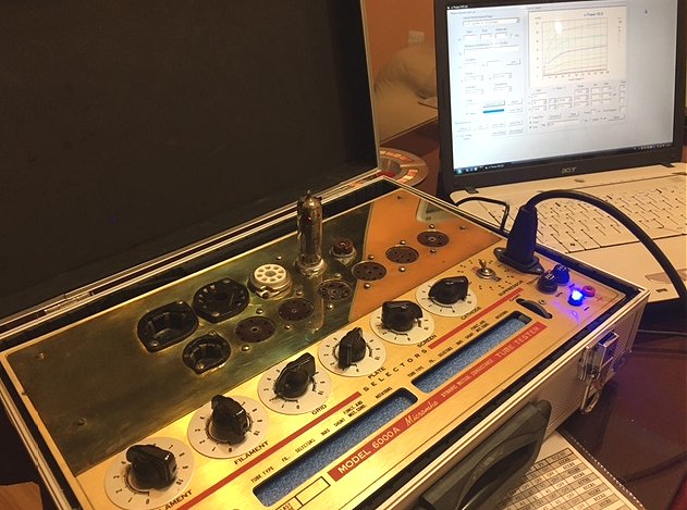
Mr. Dekker, you were right.
The pic was not tight, I don't know how it happened but it has loosened from its socket and that was the problem.
Now everything works fine, thank you very much for the help
6th of November 2021 Dominic from Australia made a beautiful 3D printed case for his uTracer! The design files are available for download!
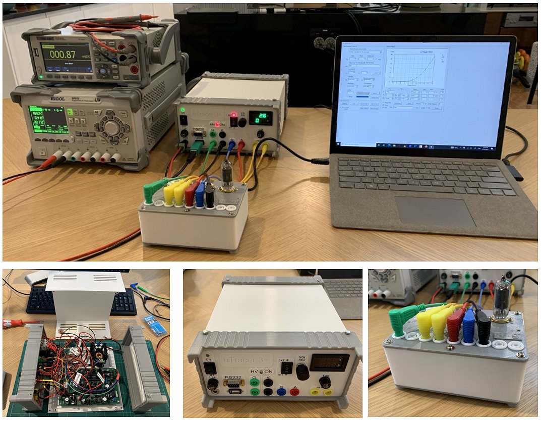
Hi Ronald,
It's Dominic O'Kelly here from Sydney, Australia. How are you?!
I just wanted to say thanks for giving me the pleasure of a terrific project with your uTracer 3+.
I thoroughly enjoyed putting it together- and the instructions were fantastic.
I also designed a simple enclosure that can be 3D printed- and I've uploaded the files to thingiverse.com in case anyone else wants to make the same build.
The links are below and I've also included a few photos for reference.
Many thanks and kind regards,
Dom
uTracer Enclosure: https://www.thingiverse.com/thing:5094091
Tube holder:
https://www.thingiverse.com/thing:5094138
23rd of October 2021 Francisco sent a beautiful picture of his uTracer that could have come straight from an interior decorator’s website!
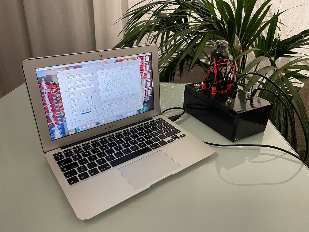
Dear Ronald and Marie Jose,
It worked!!! I had a faulty connection caused by a bad solder joint in L2.
I was able to test my first 6L6G tube with success!
Thank you very much for your support, it’s been a real pleasure to build this kit, I can only but recommend it to everyone looking for a modern tube tester.
Here’s a picture of my unit. All the best,
Fran
27th of September 2021 Johan used an old wine case for the construction of his uTracer! In his own words: “Now it not only looks good, it also smells good!”
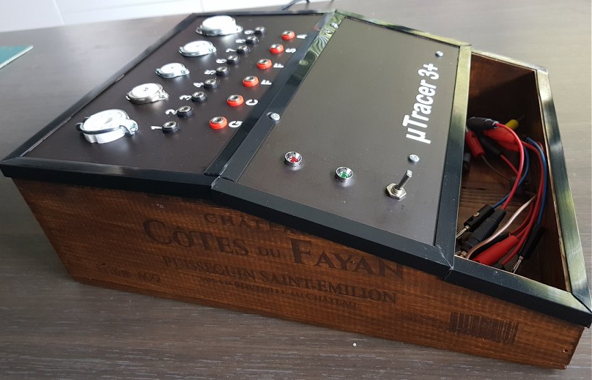
Beste Ronald en Marie-José,
Het heeft eventjes geduurd, maar mijn µTracer3+ is nu helemaal af!
In alle eerlijkheid, ik ben helemaal niet zo'n ace op gebied van electronica.
Ik heb dan ook getwijfeld of dit wel iets voor mij was: zo'n gecompliceerd project had ik nog nooit in elkaar gesoldeerd. Maar kijk: dank zij uw fantastische handleiding ben ik zonder brokken te maken aan de eindmeet geraakt. En vooral: het werkt perfect.
Een geschikt kastje ervoor vinden was ook niet evident: ik zat erover te dubben met een goed glas wijn in de hand en toen had ik het: een wijnkistje! 6 flessen Saint Emilion later werkt mijn µTracer niet alleen perfect: hij ruikt ook erg lekker.
Hartelijk, hartelijk dank vanuit Vlaanderen! (hik)
Johan
26th of August 2021 Feliciano uses the uTracer to trace the tubes he uses in the beautiful amplifiers he designs and sells (Link)!
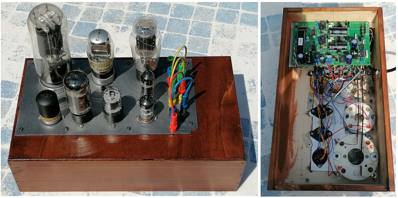
Dear Ronald and Maria Jose,
I have just finished assembling the uTracer3 + and am happy to share some photos with you.
I added an external power supply to power the filaments of tubes like 845, 300B, 211 .... which I use in my amplifiers that you can see on the web at www.ferrettifeliciano.it.
For the moment I will not replace it with uTracer6, for which you I will send a new request.
Thanks for your valuable help, best regards
Feliciano Ferretti
16th of August 2021 Michel from France is very pleased with his uTracer!
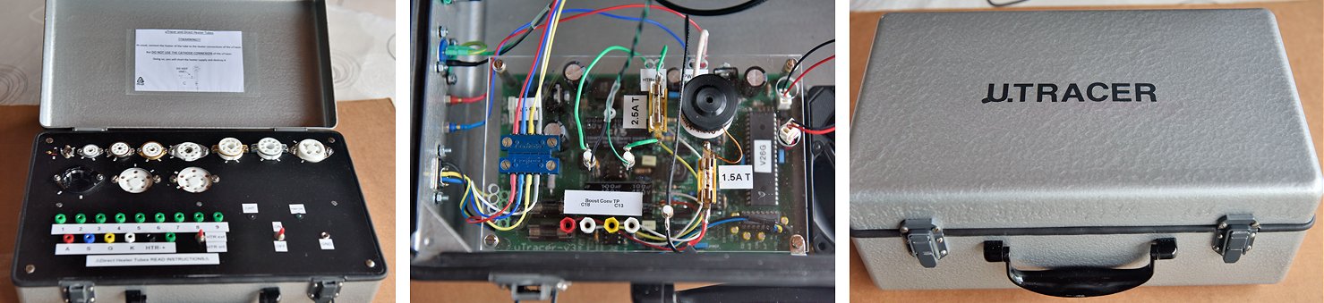
Dear Ronald and Marie José,
I did not want to send pictures of my uTracer before completion, and moreover after testing a few tubes.
Building and testing the heart of uTracer (your baby!) was a true pleasure with such a manual.
More job to refurbish the salvaged box (and old equipment for geologists, salvaged from trash!), and to build the sockets panel then cabling.
I am pretty sure I will get a uTracer6 to test more powerful transmitting tubes in a near future.
Thank you very much from a retired physicist, educated in tubes :-)
Michel
4th of August 2021 Jimmy sent me a picture of his beautiful transparent uTracer and he also made a very nice video (in Indonesian)!
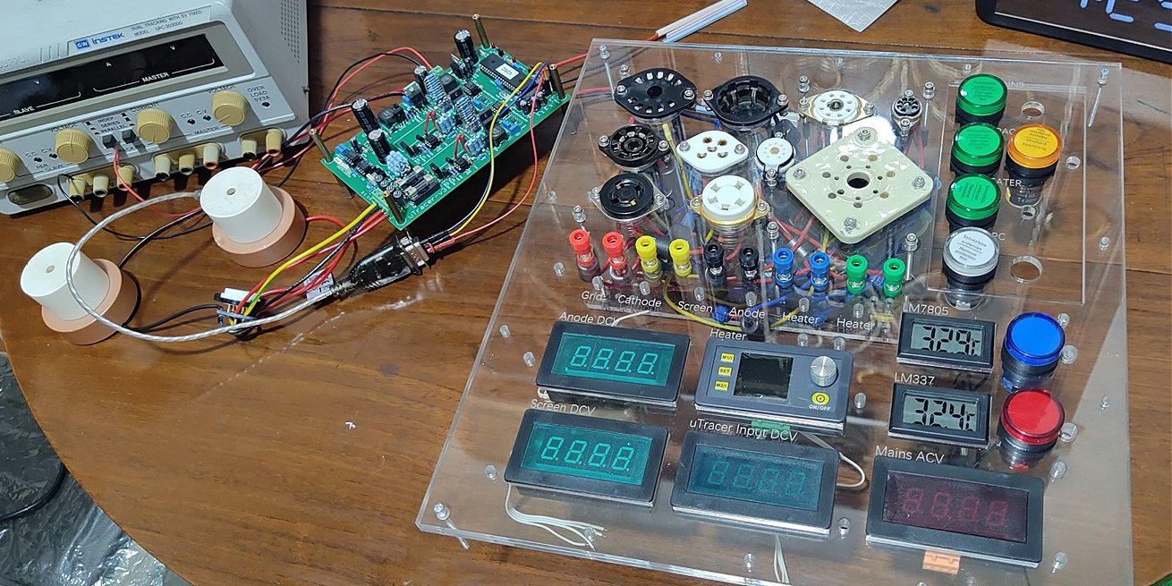
23rd of July 2021 Giampaolo sent me a few pictures of his uTracer3 and started the construction of the uTracer6!
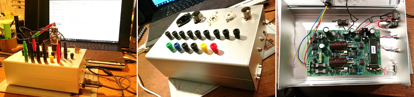
The new uTracer6 arrived safe and sound! Thank you, as always, for your availability and kindness and for your dedication in carrying out the project!
I hope to find the time to mount it and not let two years pass. I'm sending you some photos of the uTracer3 finished assembling a few months ago ... of course, compared to the beautiful creations of other users, mine is not particularly well-finished and quite anonymous. Following your instructions step by step it worked the first time!
Thanks so much again.
Best regards
Giampaolo
23rd of July 2021 Giuseppe finished his wonderful uTracer!
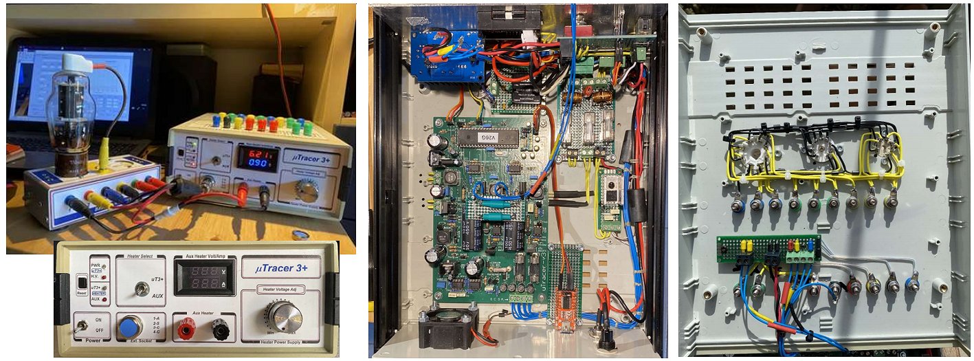
The uTracer kit is really a great project and the documentation you have made is perfect!
I assembled the circuit respecting the suggested testing steps and everything worked immediately and correctly to my great satisfaction.
Of course, after the first tests with tubes connected directly to the board to familiarize yourself with the "GUI" I disassembled an old tool to use the case.
The circuit was implemented with additional elements:
- A Step Down Converter for auxiliary filament feeding;
- A FT232RL USB - TTL Adapters for using USB connections;
- A Voltmeter-Ammeter Module connected to the auxiliary power supply;
- An Isolated DC-DC Converter Module to separate the voltamperometric power supply;
- I also consider it useful to use a fan on the line of components that are subject to increased heating.
Now I have finally completed the curves track customizing it to my needs by inserting on the top three sockets that I consider essential.
Any other socket will be connected externally through the front connector.
Thank you very much and best regards from Genoa (Italy),
Giuseppe Suanno
27th of June 2021 Ahmed reported the successful completion of his uTracer.
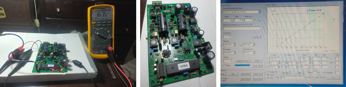
My thanks Ronald and Marie José for this wonderful tube tester.
Today I have completed the assembly of my utracer3 and all the tests without any problem.
I really enjoyed building this device.
All are clear on the manual you did a great job I appreciate your great effort.
Best regards.
7th of June 2021 Soon-Mo from Korea organized a group build of more than 15 uTracers by a group of tube amplifier enthusiasts! Read the story of their activities in his own words.
I live in Korea and am one of the staff of an internet online community called AMPMANSA (people who makes amps).
https://cafe.naver.com/kosskid
This community was created in 2012 and has approximately 3,300 members. Members are mainly people who make vacuum tube amplifiers as a hobby.
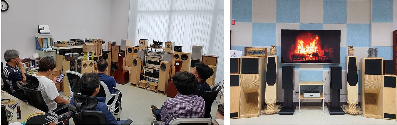
Left: evaluating speakers. Right: listing room
From an early age, I was interested in making my own electronic devices. I joined this community about 3 years ago. Because I am working in IT field, so I don't have much expertise in electronics fields.
Members share information with each other and freely engage in technical discussions online. We also continue to work on projects to design and measure circuits and build amplifiers. Basically, all circuits design and measurement information be shared by online. Anyone can use it for personal, not commercial use.
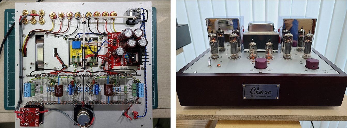
EL84paraSE
Recently, we are working on a project to produce uTracer. It is because if we want to design an amplifier using preferred tube, we have to tune circuits by measuring the tube directly with uTracer.
A few months ago someone asked me to build a low power single tube amplifier using EL95 tubes. There was no information on the triode connection in the datasheet, but I successfully built an amplifier by getting loadline of the triode connection from uTracer3.
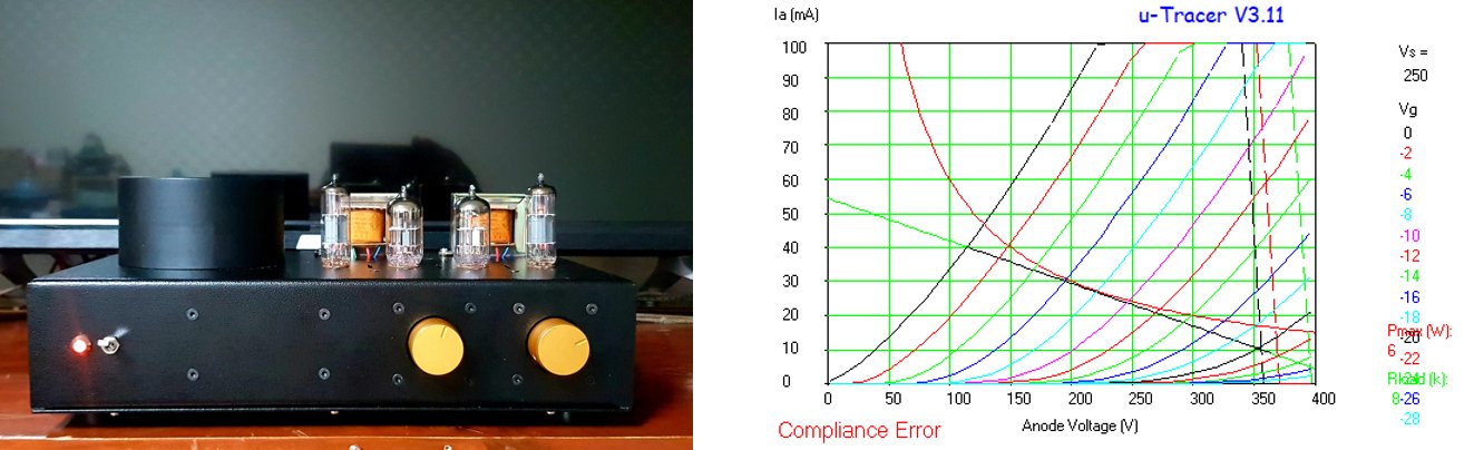
Left: EL95SE with Telefunken OPT. Right: EL95 loadline
We made an amplifier uTracer enclosure utilize wood base (the standard case in our community) and the aluminum top plate is designed by CAD.
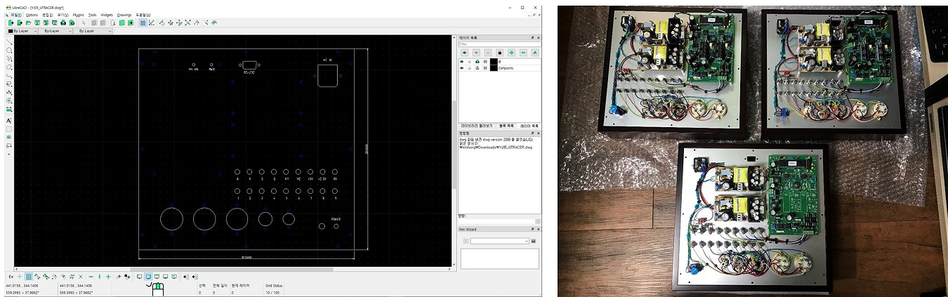
Left: uTracer top plate design. Right: uTracer serial production
For members with poor eyesight or those who are not confident in soldering, I did the work for them, and I made a production guide including photos and posted it on the Internet.
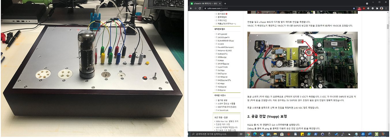
Left: measuring KT77. Right: Step-by-step online guide.
The first thing I did after completion was to verify the load line of the EF6 tube of the amplifier I made recently.
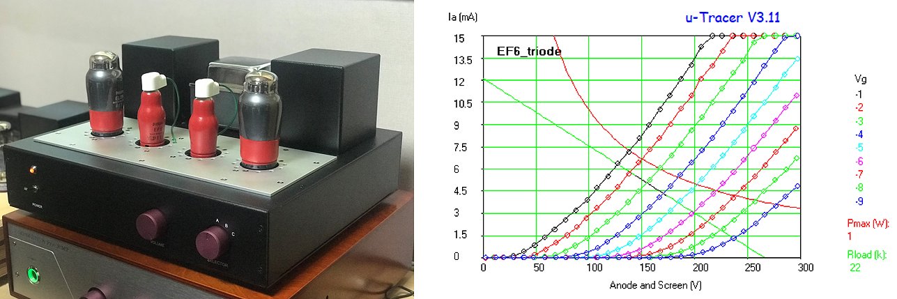
Left: EL3nSE. Right: EF6 loadline
There are so many good resources on your website and especially the well-written manuals that made our project easy. Also, I am very grateful that uTracer will be a great help in the development of our online community.
Kindest Regards,
Soon-Mo
15th of May 2021 Tom finished his uTracer and is making first tests.
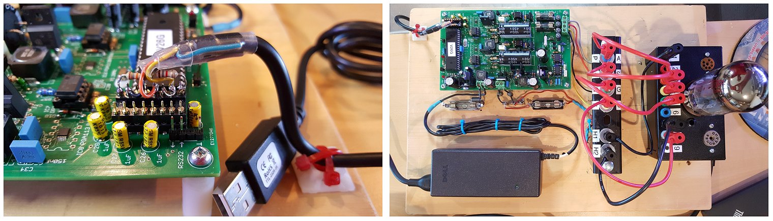
The parts you sent to me for repair arrived, thank you. I liked the postage stamp used on the packet!
And more Pics.
The first picture "uTracer3+ Temp Assy.jpg" is how I have mounted the uTracer on a board for use until my enclosure arrives from China - July or so. When I am permitted to purchase the uTracer 6, I will use the same temporary board to initially test the model 6!
The second picture, "uTracer3+ Comm Header Mod.jpg" you may find interesting. I built the uTracer using the RS-232 interface and tested the uTracer for proper behavior, as you suggested, before I tried the TTL-232-5V USB cable. At this point, I looked at your elegant implementation of the USB cable and thought I would simply use a 16 pin header placing the components on the header. I am now able to easily switch back and forth between the RS-232 and USB ports. I thought this might be useful for future troubleshooting, and I did not want to remove all the unused parts for concern of damaging the PCB. I rather like it.
Some comments.
- Curiously, the USB interface was not dependable using GUI version 3.11. I would get Error 6 - Overflow on the quick test. When I put the RS-232 chip back in, the software operated flawlessly.
I was a bit discouraged thinking my mod was at fault. But then I thought I would update the GUI to 3.12 and see if that helped. It did! All the GUI functions worked perfectly as designed.
- And YES, copy down the calibration values before updating the GUI........ At least it gave me the chance to calibrate again with increased familiarity.
- Out of an abundance of caution, I added a heat sink to T2. I notice that this heat sink gets slightly warmer than ambient. I will leave the heat sink in place.
The tube being tested is a Valve Art - 6550A. Yeah, I got a "Compliance Error". So now I am off to build the 1 Amp upgrade for the uTracer3+ and I will use the inductor you sent to me for the boost converter speedup. Do you think the addition of a heat sink to T14, T9 and/or t17, T12 would be of benefit after the 1 amp modification?
Cheers,
Tom
4th of April 2021 John added another beautiful uTracer to Poland!
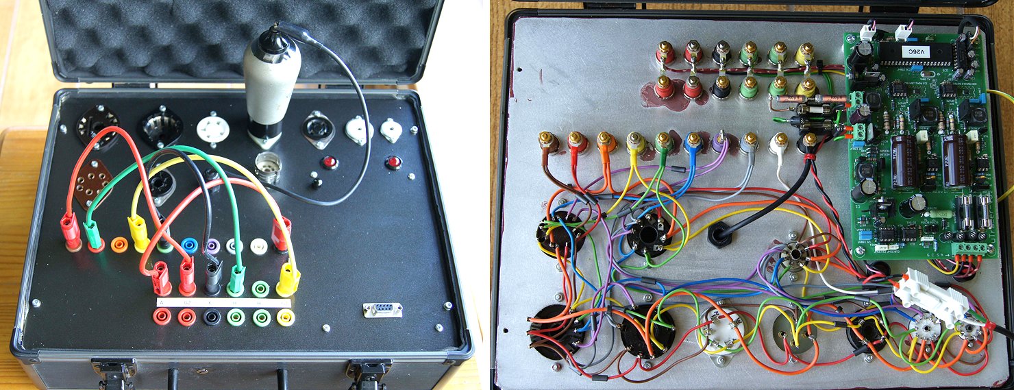
It's been ages since I built this excellent kit and, like a few other people, I only just got round to putting it in a box. My enclosure is nowhere near as pretty as some folks' but since it's just for me and it lives in my workshop I think that's OK (ish). It is built on a thick aluminium plate, painted with Hammerite (what else) and mounted in an old Jessops camera accessory case.
I used your suggestion of "telephone exchange" plugs and sockets, colour coded 1 - 9 so I don't have to count, and for the uTracer connections I used the safety-first idea of red for danger, green for safe etc, It works well and is simple to use.
Ronald, this is a beautifully produced kit and is really useful (even before the box).. Sorry it took me 4 years to send the testimonial. So you have another completed unit up and running in Poland!
Please add this email address to your mailing list as the one you have if not valid anymore.
Best regards
John
28th of March 2021 Ihor finished his uTracer3 with his ESP32 based webinterface! Click here to check out his project!
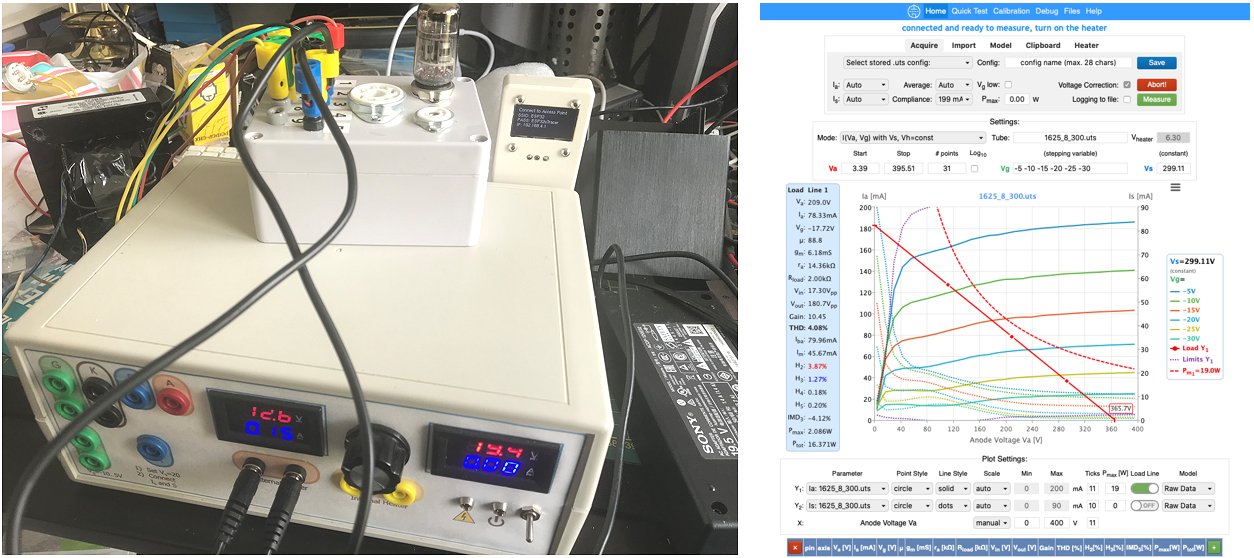
I hope you are doing well!
I just wanted to update you that the ESP32 project works great for many users that send me emails. After many communications I incorporated many suggestions and polished the interface quite a bit. Lately there are not so many messages because things just work :)
But, most importantly, I just wanted to share a few photos with my *finally* finished uTracer :) Long time ago you mentioned that you could post them on your website with some short story.
I bought and assembled it about 1.5 year ago. Since then it was always in use but it was never finished. I really enjoyed building and using it and in parallel, I also read, I believe, all the posts and explanations on your website and asked you a number of questions over time. The clear descriptions in your weblogs trigged me to add an external power supply and then build the Grid Loupe. While replicating the grid loupe that you described, I learned how to design and print PCBs and the resulting add-on is working great for me. Later I explored the possibilities to communicate with uTracer not only from Windows and RS232 cable but also bluetooth. I was not happy with that, so I decided to play with WiFI-capable ESP32 modules. As a results, I went into programming the webinterface for uTracer, based on ESP32. It took quite some time but now it is working and quite a number of people using it right now. Additionally to just driving the uTracer from the webinterface I also went to tube modeling and added to the functionality of that ESP32 module all the method that Derk Reefman described on your website. Last week, I finally placed my ESP32 module into the case of uTracer and screwed all the screws. Now it is time to focus on measurements and building amplifiers!
Cheers,
Ihor
The ESP32 webinterface in Ihor’s project site: http://boffin.nl/wp/utracer-and-esp32/
An item on the interface on my Lab Notebook page: https://www.dos4ever.com/uTracerNotebook/Notebook.html#ESP32
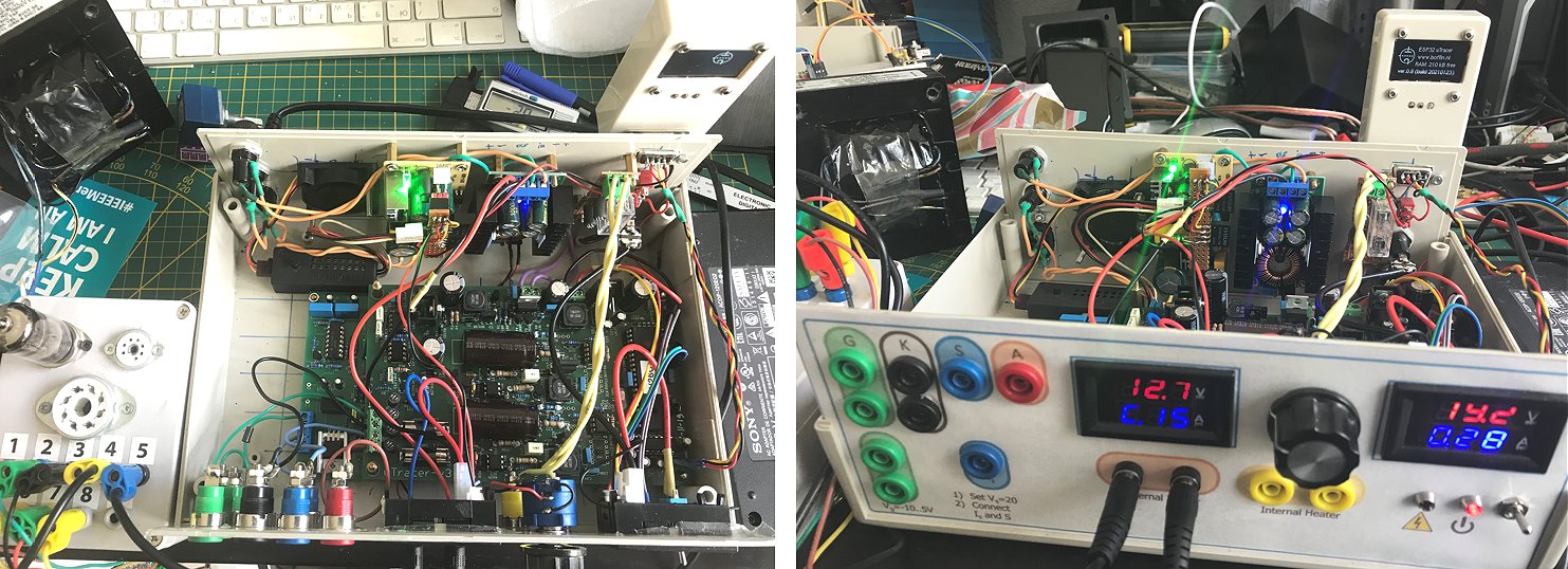
10th of March 2021 An enthusiastic uTracer user near Lyon in France constructed his uTracer in a tea box!
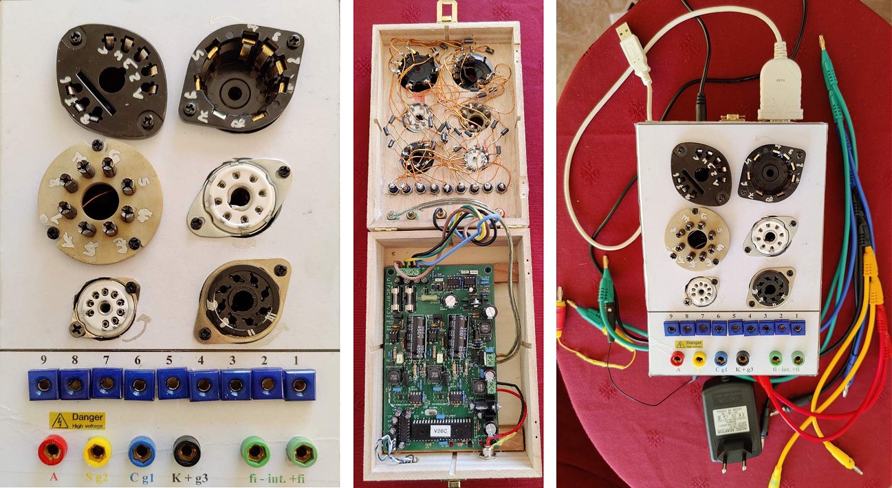
I’ve finally finished wood, plastic, work to have uTracer on a small box. This is a Tea Box quite compact with some additional plexiglass to have a stronger cover. I’ve used galva (http://www.f5bu.fr/galva-download/) software to print the top hole position and then labelling.
Find enclosed pictures and then some curves.
This is a real fun, to measure tubes check with datasheet and see how it behave col, hot, …….
I just miss multiple step definition (va,vg both defined with start stop and increment or steps ) on the software.
Many thanks for your support.
8th of March 2021 Luigi A. Bocca from LAB Audio Technology finally finished his uTracer, and it compares well to commercial tube testers!
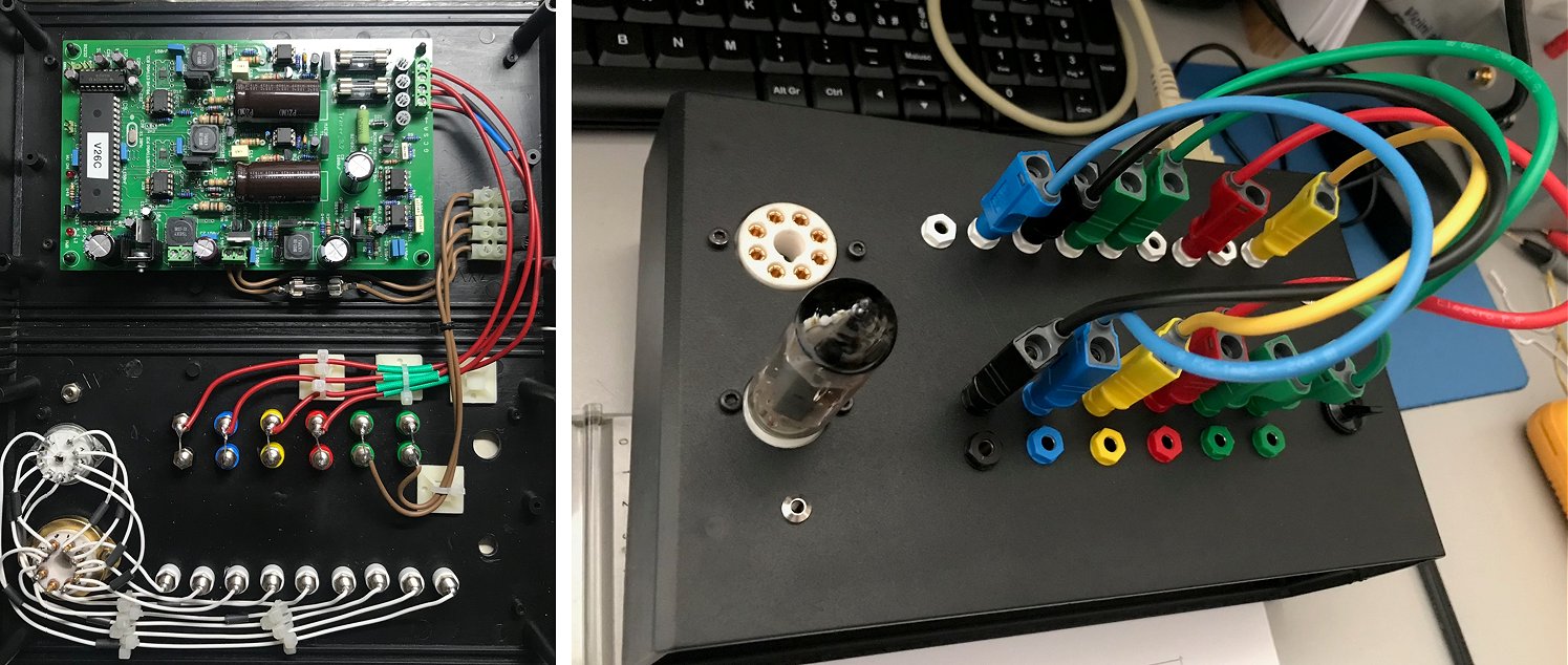
Greetings form Italy!
Almost 5 years have passed since the purchase of the utracer and I finally found the time to finish your excellent project.
I preferred the use of pins instead of rotary switches, the use is extremely quick and simple.
The utracer joins a TV-7 and a modern maxipreamp2, but the utracer is certainly the best for profound analysis of the characteristics of a tube.
Thanks again for your work.
Yours sincerely
Luigi A. Bocca
www.labaudiotech.com
www.labaudiocables.com
www.valvoleaudio.com
7th of March 2021 Markus Wolschek finished his uTracer3+ and he is very happy with it!
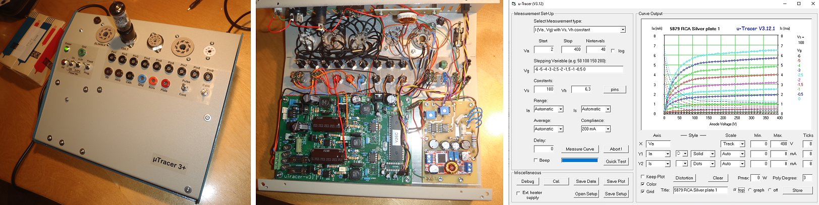
As promised a few images.
For ECC83-type and 6L6/EL34 I've hard-wired sockets since these are the tubes I play around with most.
I've added a regulated heater supply that can be switched to 6.3V or 5.67V (90%).
Also I included plots from a nice 1971 Heerlen CV492/ECC83, a Mullard EL95 (most likely from 1975), a RFT EL34 and also a RCA 5879 :-)
Thanks again for developing such a fantastic device!
Have a nice Sunday evening!
Best regards,
Markus
3rd of March 2021 Have a look at Matthias Stolpe’s fantastic uTracer! With rotary switches!
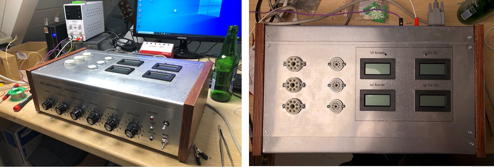
Hallo Ronald,
Anbei die Bilder meines fertigen uTracer3+.
Vielen Dank für alles.
Liebe Grüße aus Berlin
Matthias Stolpe
28th of February 2021 More or less by accident I discovered that there quite an active uTracer community in Japan! Below some impressions and links.
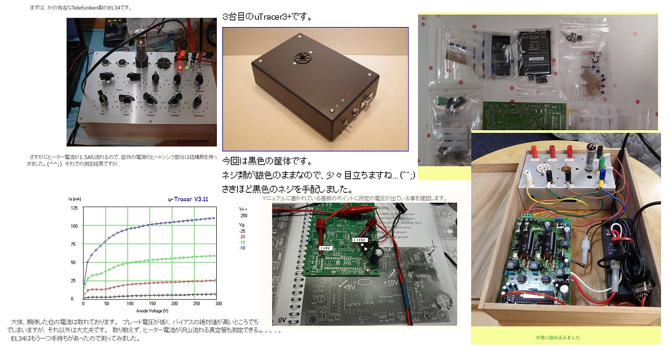
https://jf1kmc.blog.fc2.com/blog-entry-2113.html
https://community.phileweb.com/mypage/entry/3311/20201003/66135/
http://www2s.biglobe.ne.jp/~ja3wzt/uTracer-Kit.html
https://ameblo.jp/lavie60/entry-12468043364.html
13th of February 2021 Bert Proeme sent me an account of his very nice uTracer (in Dutch)!
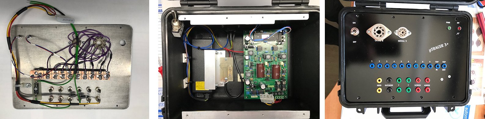
Beste Ronald,
Ik had beloofd wat foto's te sturen als mijn uTracer 3+ klaar was.
De print is met voeding ingebouwd in een klein kunststof koffertje waarop bij openklappen de frontplaat te zien is.
Enkele verbindingen met de print heb ik met connectoren gedaan om de frontplaat makkelijk te kunnen demonteren.
Om de frontplaat te bevestigen gebruik ik M3 boutjes met verzonken kop maar die zie je nog niet op de foto's omdat ik die net gelakt heb.
De manipulatie stekkerbusjes zijn vrij universeel opgesteld waarbij ik wel een TOP in en uit heb gemaakt want een collega heeft buizen met een top aansluiting zodat ik die ook kan testen. Tussen TOP in en uit heb ik een smoorspoel gemonteerd en over de draadjes naar de voeten heb ik ook de RFI busjes geschoven.
Omdat ik buizen gitaarversterkers maak heb ik genoeg aan de twee voeten die nu gemonteerd zijn voor de gebruikte buizen in dat soort versterkers.
m.v.g.
Bert Proeme
9th of February 2021 Tae very much enjoyed constructing his uTracer!
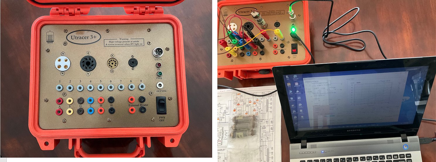
Ronald and Marie-
Thank you very much for your dedication of sharing and providing good project (uTracer 3+).
Last year, our Gulfstream Aerospace Long Beach had financial crisis due to pandemic, our department and our branch were closed forever, it was a kind of the bad part of moment in my life.
But, when I was building and troubleshooting minor issue, I enjoyed full of happiness and it seemed like I rode and /or traveled time-capsule into my young age, elementary school times.
That time, I was shocked when I could listen radio station with crystal radio I made.
I was happier than my big promotion during my career, when Utracer drew the lines on my computer.
It was so valuable and good time in my life, thank you again.
God bless on your family!
Best Regards
24th of January 2021 Robert Johnston finished his very fine uTracer!
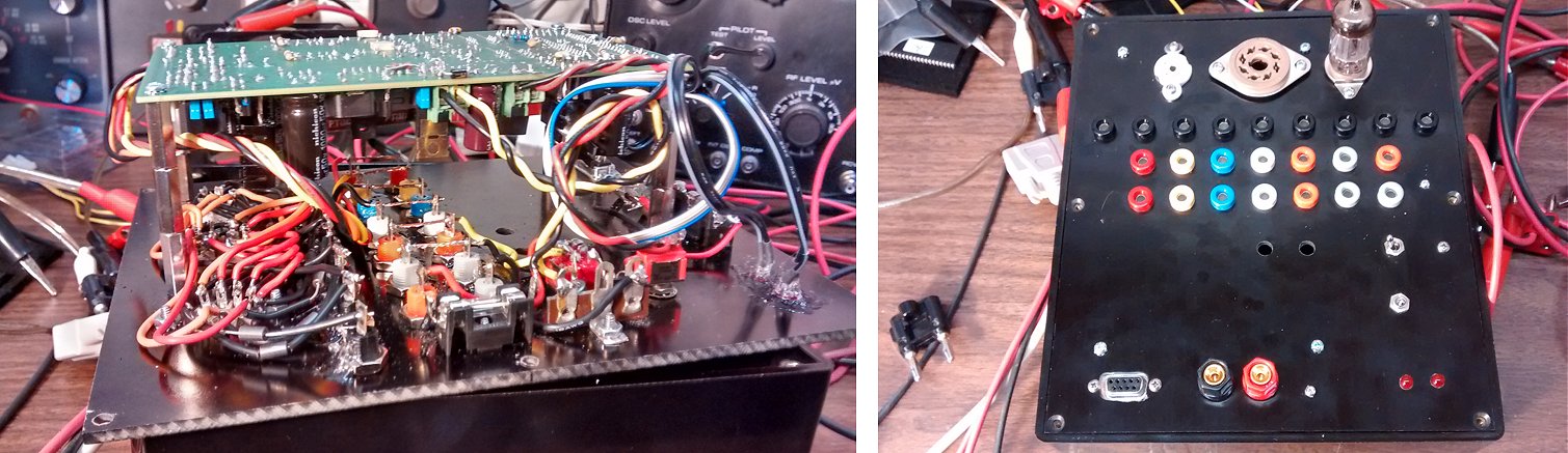
Ronald
Having just competed my uTracer I have been testing my unit.
Let me first express the fun I am having with your creation.
The quality and creativity that has gone into this design is most enjoyable to explore.
Take care
Robert G Johnston.
21st of January 2021 Bernie Dator from the Philippines(!) finished his beautiful uTracer!
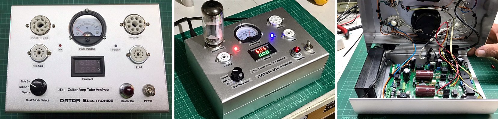
Hello Marie Josié and Ronald,
Happy New Year to both of you. I just want to report that my tube tester was finally completed. Everything working fine as well as the software. I really love this tool to analyze the characteristic of the valve tubes more better and to re-bias to its most optimal performance. More power to your team and best regards.
Bernie Dator
Manila Philippines
10th of January 2021 Petr sent me a few pictures of his very nice, non-nonsense uTracer!
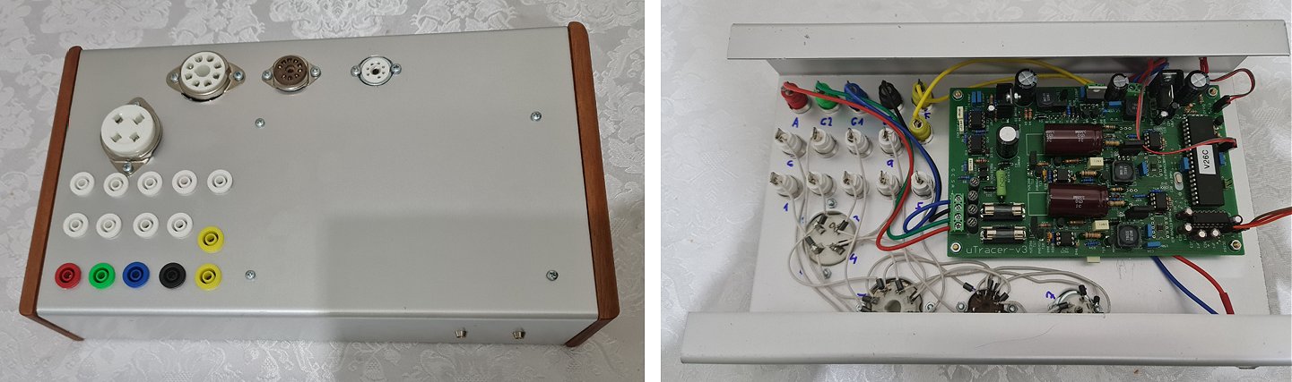
I have almost completed my uTracer (I finished the pcb and calibration long time ago but I was too busy to complete it then) and it is working nicely! (attaching some pictures of my build)
Thanks again for the kit and happy and healthy 2021 !
Petr
9th of January 2021 Róbert Juhász is the first this year to send me some pictures of his splendid uTracer!
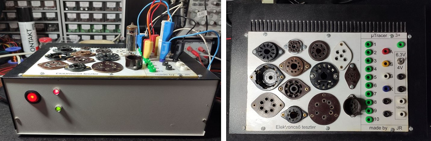
Dear Ronald & Marie-José,
This is very good news. I have been using uTracet3+ for years and I am very happy with it. I would also like to buy the uTracer6 kit. I am sending two pictures of my own uTracet3 +.
Best regards and happy new year,
Róbert Juhász
30th of December 2020 On almost the last day of the year Patrick Schaefer sent me a few pictures and a testimonial of his extremely compact uTracer!
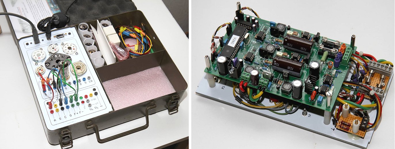
Dear Marie-José,
Dear Ronald,
hopefully you are well and you and your family have survived the epidemic so far unharmed?
Today I finally found the time to take some photos of my µTracer and send them to you for your gallery. Please feel free to use them on your website if you like.
I built this device in the summer of 2019. As housing I used the accessory case of an old army radio. I got it cheap at a ham radio market and immediately had the idea to use it for a tube tester. So everything stays together and the accessories do not get lost.
The front panel is a printed circuit board. Full Copper, white solder mask, black silkscreen. The tube sockets are wired in the recommended way and fitted with ferrites. Besides the RS-232 port I also provided USB. Both inputs hang in parallel, i.e. TxD outputs connected together and RxD inputs ORed via diodes.
Between the words "µTracer" and "3+" is a small hole where you can pin a note. Here info cards can be attached, with the setting and wiring instructions for the tubes. However, I have not used this feature yet. Your GUI is able to remember the tube pinouts and settings -- this is sufficient.
Best regards
Patrick
BTW: I still have two of these front panels left. If someone should ask,
please refer him/her to me.
29th of December 2020 Teemu Rajala sent a few pictures of his compact and beautiful uTracer. It is a true tribute to Pentti Pelto!
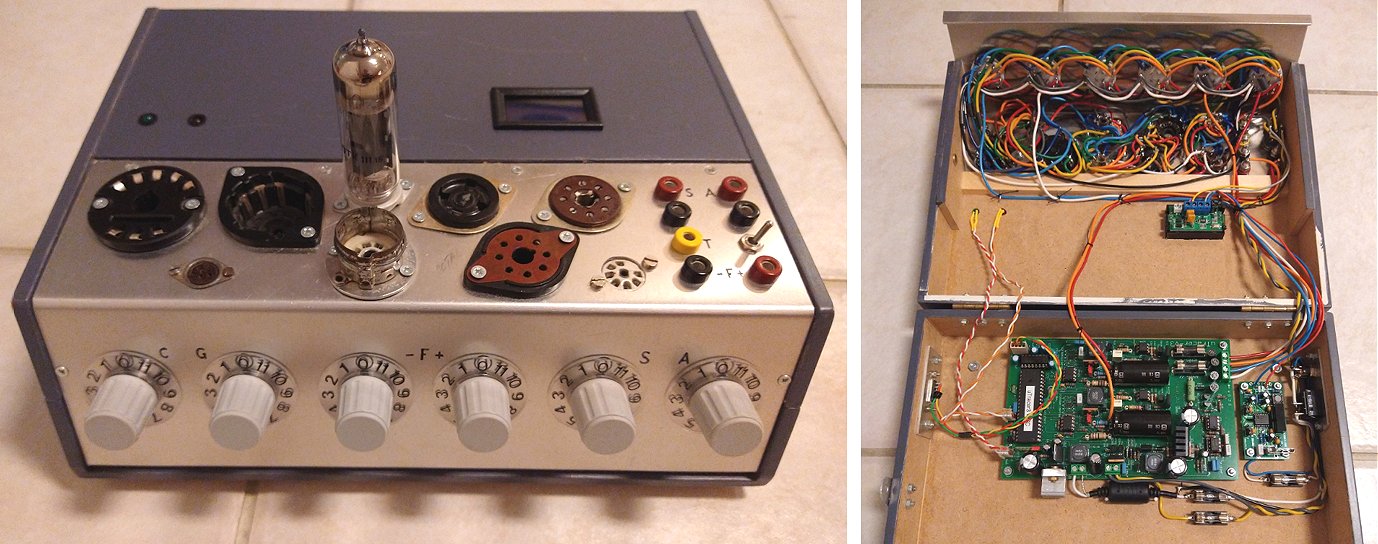
Hi Ronald,
Pentti Pelto wrote to you on 17th/Dec/2017 and gave an update concerning his and Salasmaa's uTracers. You have included this great piece of information in the uTracer Testimonials web page.
As Pentti wrote, he didn't have enough strength to complete the tube tester, and he passed away only four months later. I bought Pentti's unfinished tube tester from the local radio amateur club summer camp in 2018 and decided to continue his work.
Now two years later the tester is finally wired and it seems to work perfectly without oscillations. I'm amazed how accurate results I'm able to get also for low voltage, direct heated battery tubes with the original unmodified uTracer circuit.
Wiring of the tester wasn't too easy, because of a quite dense area reserved for the tube sockets and rotary switches. I have added two extra features to the tester. One is a possibility to supply external voltages to the heaters, because I have lots of direct heated tubes to be tested. I added also a voltmeter for external heater voltages, but it took some time to figure out how to power the meter without messing up voltage levels on the cathode. Finally, I decided to power the meter from the 19 volt main supply via a 5 volt regulator and a USB voltage isolator.
Unfortunately I don't have any information about Salasmaa's uTracer.
Best Regards and Happy New Year 2021!
Teemu Rajala, OH3KUN
26th of December 2020 Jon Hoover sent me a few pictures of his very nice uTracer construction!
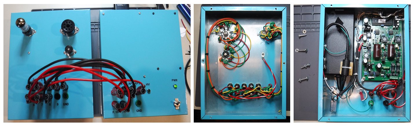
Hi Ronald and Marie-Jose,
What a cool kit you have! I feel very proud to own such a nice piece of test equipment. Especially since I built it! I have included some pictures of my completed uTracer. It works great. I used stacking banana plugs on my jumper wires so I wouldn’t have to drill so many holes in the chassis. I installed 7, 8 and 9 pin tube sockets as this is all I really ever see. I tried to find a Tektronix Teal paint color for the box. This is as close as I could get. Thanks again for making such a cool item available for us tube enthusiasts and for all the hard work on the construction manual and the packaging. Top notch!
Regards
Jon Hoover
12th of December 2020 Tomas Lannestedt sent me a few pictures of his amazing wireless ESP32 based interface (read also here)!
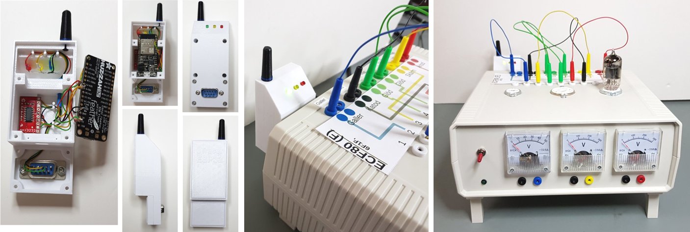
Hi Ronald,
Thanks for the newsletter. I always read them.
And thanks for the tips on the ESP32 software from Ihor. I tried it and it works really nice. I have built in my ESP32 in to a "police scanner" like case attached to the DSUB on the back on my uTracer. I have described it here, in Swedish but I think you get most of it from the pictures. https://elektronikforumet.com/forum/viewtopic.php?p=1576073#p1576073
I attached some of the pictures as well
VBR
/Tomas Lannestedt
28th of November 2020 David Holland sent me a few pictures of his elaborate uTracer!
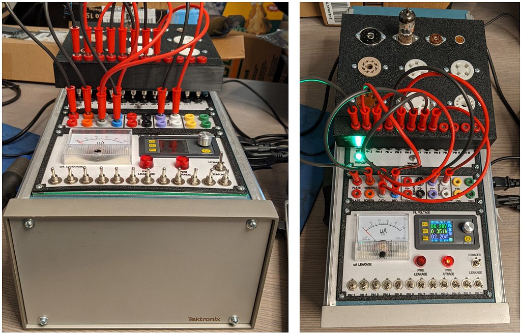
FWIW,
Attached are a couple of pictures of my UT3+ build. External filament supply, leakage testing, removable socket panel. Seems to work pretty well, and is completed just in time for the UT6. All in a very stylish, and sheek Tektronix box.
You recently said to send in pictures of our completed UT3's, so I am...
Hope everyone is doing well, and is safe,
Cheers
David
27th of November 2020 Dieter Declercq reports his uTracer working!
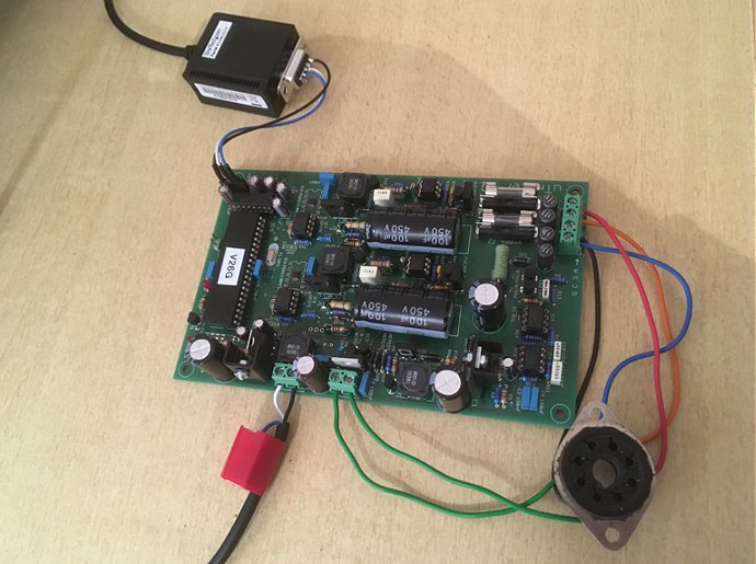
Dag Marie-José
Kort even melden dat de utracer gebouwd en succesvol getest is. Nu op zoek naar een gepaste behuizing...
Ik heb nog een aantal componenten op overschot, vooral weerstanden, waarvoor dienen die?
Alles was prima verpakt, niets tekort en de handleiding is heel duidelijk.
Alvast bedankt & vriendelijke groeten
Dieter
21th of November 2020 Aart van de Water enjoyed building his uTracer!
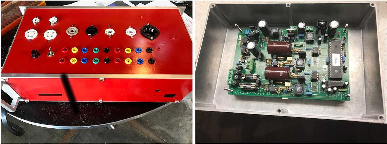
16th of November 2020 Egil Hansen sent me a few pictures of his very nice uTracer!
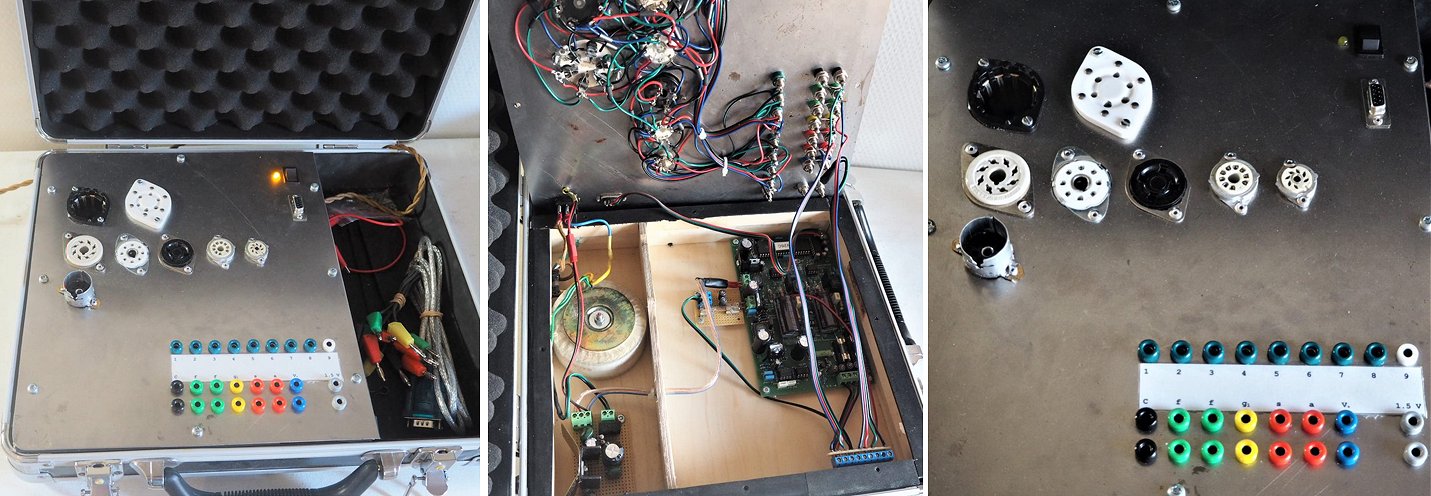
Hi Ronald!
Thank you for the progress report. I will certainly order the new version of the uTracer when it becomes available.
Please enjoy a few photos of my own build of the uTracer 3+.
Best regards
Egil
15th of November 2020 Kenneth Hutchinson rewired an old Heathkit tube tester to house his uTracer! (Did I even mention how much I love rotary switches?)
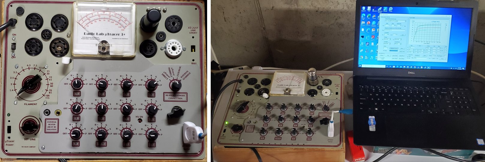
Hi Ronald,
Some time ago, two or maybe three years, I bought and assembled a uTracer kit. When it was finished I tested it out briefly using clip leads to a spare tube socket as so many have done before me. And then I set it aside to work on other things. Well, now that version 6 is nearing release I have finally put my 3+ in a housing so that I can use it. There are still a few final details to tie down but at long last it is in operation!
I've attached a few photos. I built it into an old Heathkit TC-2 tube tester housing. A tube tester has a nice array of tube sockets and it has a transformer that can be used to power filaments. Like many others the Heathkit tester's setup switches do not lend themselves easily to performing the switching the uTracer needs so I had to replace them with rotary switches. The result is a real rat's nest of wiring that I tried to tame with copious amounts of ferrite beads. In my testing so far that seems to be working but a tube tester with a more elegant and capable switching arrangement might have made a better host. I repurposed the meter to measure the filament voltage and added a custom face design to it for that use. In a few brief tests using an AC filament supply with indirectly heated tubes does not seem to cause an issue with the uTracer. There is a switch to select the heater source and it also disconnects the uTracer cathode in the direct position but of course if you don't remember to set the switch to the direct position you can still connect the cathode and heater signals together.
There is also a picture of the uTracer in action testing a 12SK7 that was pulled from an old Hallicrafters S-38 receiver that is next on the list for restoration. The closeup of the test screen indicates that the old RF pentode still has a lot of life left in it!
Anyway I hope you enjoy my humble efforts at giving my uTracer a proper home. I think I will make a lot of use of it now that it can easily be used with the tubes I will want to test.
Thanks for all your efforts to make this available to the rest of us.
Kenneth S. Hutchinson
11th of November 2020 Igor Bardashev just finished his very neat uTracer!
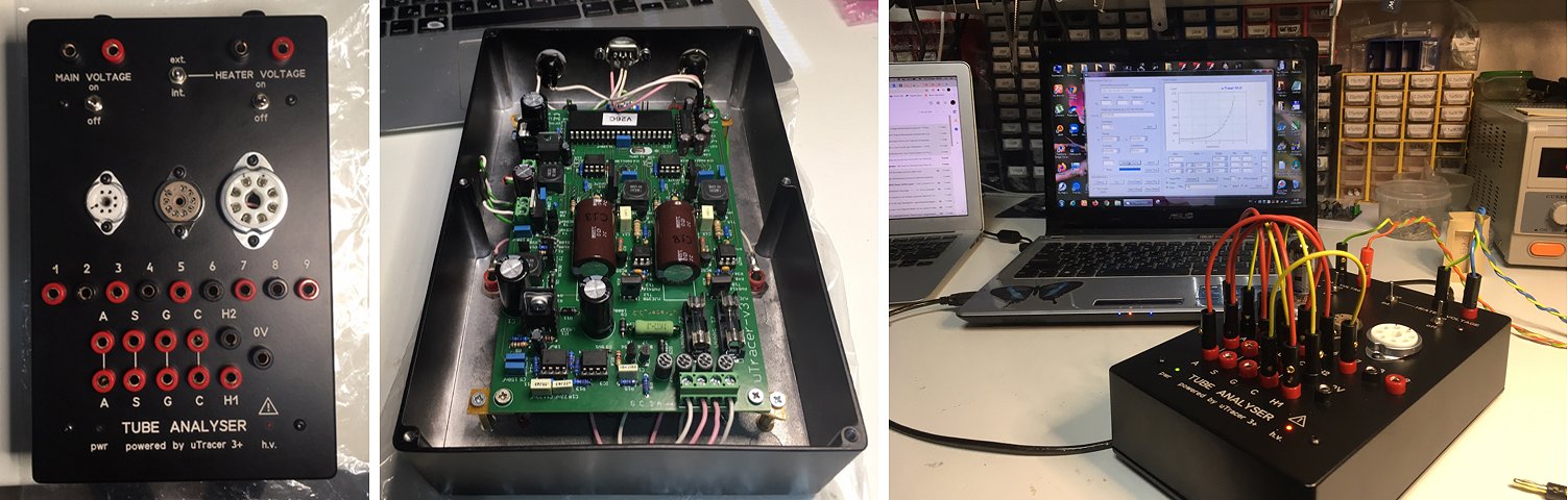
Hi Ronald,
Today I finished the final test procedures and made my first test on a real tube.
Thank you for such cool and powerful equipment!
I've attached a couple images of my finished tester.
If you want feel free to post it on your site.
Cheers,
Igor
5th of November 2020 Tom Coates sent me a picture of his very nice uTracer housed in an old Vidor battery portable radio case!
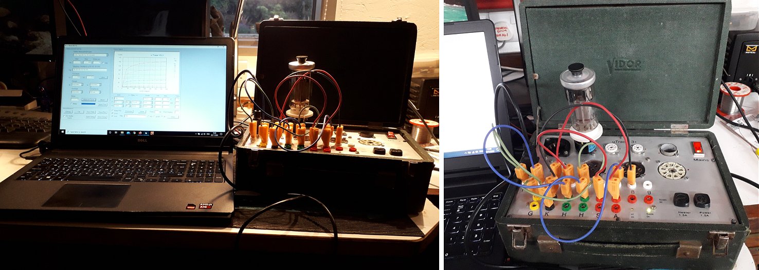
Hello Ronald,
I hope you and your family are well and surviving these difficult times.
I have been been finding my uTracer 3+ very useful and great to use but find it could do with more voltage and current capability. Looking at your website, I noticed you have made a uTracer 6 which would be very nice for testing my Russian GU50s! Are you selling the '6' kits yet? I would be interested in buying one soon since our imminent departure from the EU will probably make them more expensive here in UK.
In case you were wondering, I housed my 3+ in a case that originally belonged to a Vidor battery portable radio which stores easily and having a lid, keeps the valve sockets clean. The valve under test is a GU50 plugged into an adaptor which fits an octal socket.
Best Regards,
Tim Coates
21st of October 2020 Evert-Jan sent me a picture and a very nice testimonial!
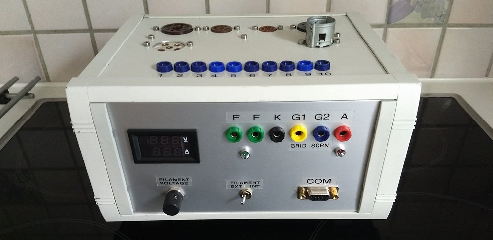
The tubetester kit developed by Ronald is the no.1 tool for me.
It’s used by me for testing the quality of the tube’s i need for restoring old radio sets and also building audio amplifiers.
A huge’thank you’to Ronald and Marie-Jose for providing so much info on the website all for free! This is usuful stuff. Great to learn more about tube’s and electronics, all explained in normal words and with common sense.
When my tester died… they were verry helpful by mail to get it up and running again. Thats so nice.
Stay well to you all!
Evert-Jan
10th of October 2020 Rijk Jacobs sent me a few picters of his very fine uTracer with a row of beautiful rotary switches!
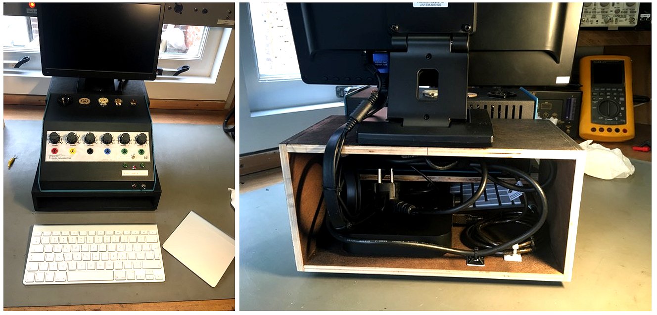
Hallo Ronald,
Na wat aanloop perikelen werkt de uTracer nu goed en inmiddels ingebouwd met NUC en LCD scherm samen zoals te zien in beide foto’s. Gister toch nog externe gloeispanning mogelijkheid toegevoegd, wilde nog wat NOS Philips 4699 testen maar dat trekt de uTracer gloeispanning niet( 4V-2.1A). Voeding voor de NUC en LCD haal ik via twee instelbare DC-DC converters(beide 12V) ook nog uit Laptopvoeding kan alles handig via 1 220V~ stekker. Apple keyboard en trackpad via bluetooth op de NUC passen onderin kastje handig om op te pakken zo.
Dank voor de snelle service zover en deze fijne buizentester
5th of September 2020 Thomas Unger reports his very fine utracer finished!
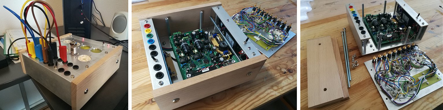
3rd of September 2020 Have a look at Jay’s Tube Analyzer! (powered by uTracer3+)
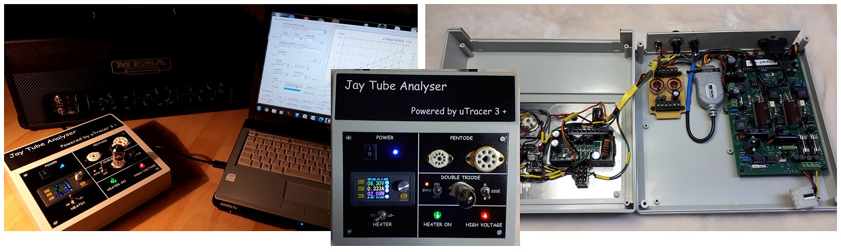
22nd of August 2020 Bogdan Siwanowicz finshed his nce and compact uTracer with horizontal tube assembly!
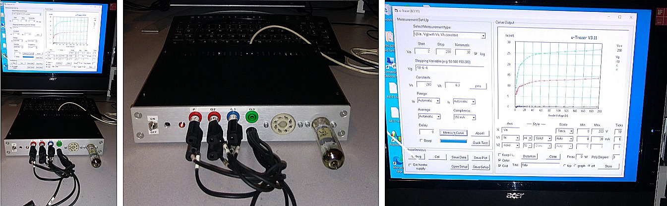
19th of August 2020 Jorma Pylkko from Finland finished his very nice uTracer with the high current option!
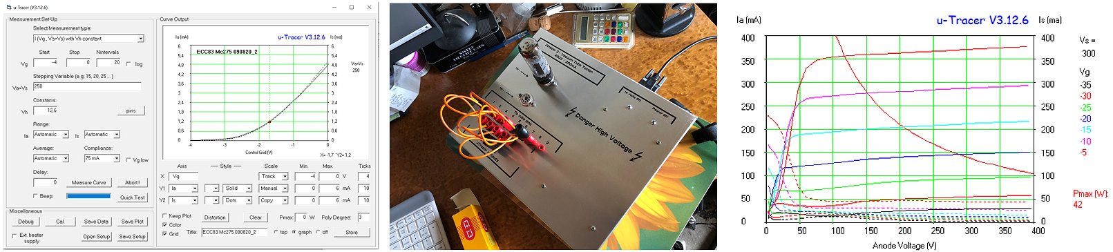
Dear uTracer Team - Marie-José, Ronald and family members,
Good things take time to mature, especially this is the case with my uTracer project.
Initially started in 2016 and used a in bare PCB form for some years, I finally managed to finish the project i.e. build it in a Hammond aluminum housing with all connectors, sockets etc. included.
Please find a photo of the finished uTracer. On the contrary what the front panel says, I have already upgraded my unit to HC (High Current) version. It works brilliantly when characterizing high power output tubes e.g. EL34 and KT88 and still the readings from low current tubes such as ECC83 are totally stable and noise free. Another attachment is a ECC83 measurement (left), you see that even at low currents this HC version is stable and noise free. The second measurement is from KT88 output tube (right) showing the high current capability of uTracer.
There are still some finishing touches I want to do e.g. add wooden end covers to make the box less industrial looking.
Thank you again for this brilliant device for valve/tube enthusiasts and hobbyists!
Best Regards
Jorma
12th of July 2020 Eric Bots finished his uTracer and his son Joris made a beautiful 3D printed enclosure for it!
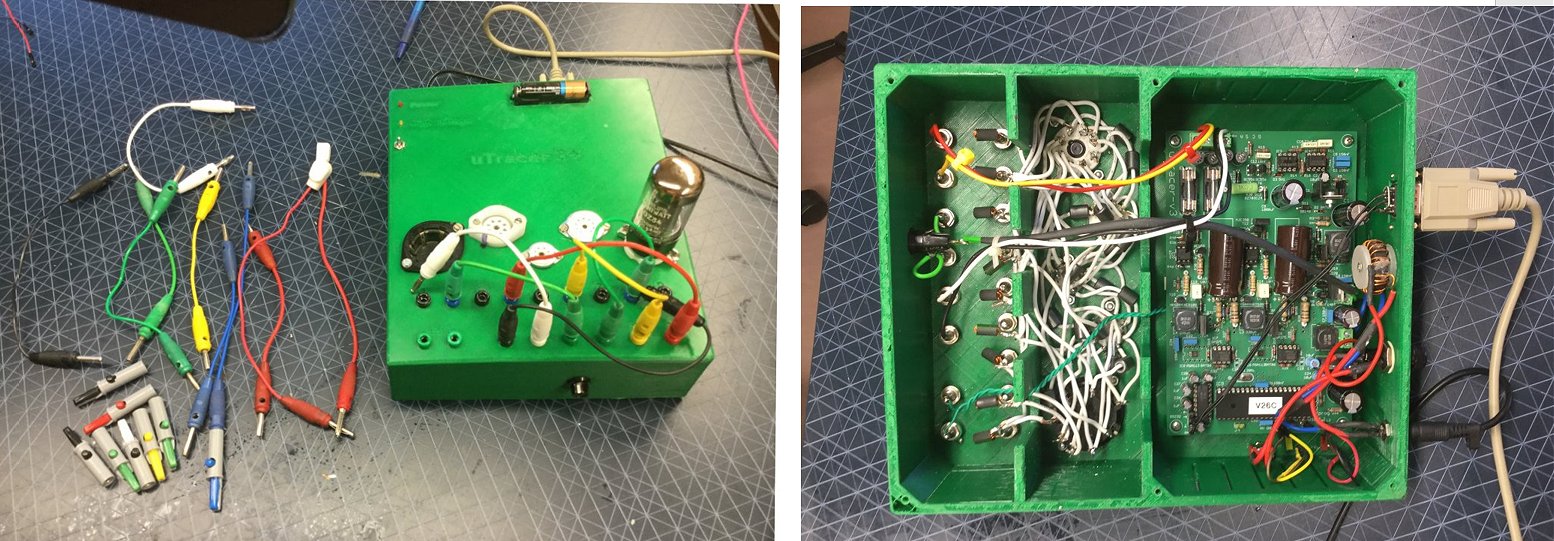
You can print one yourself!
Please find the STL files here https://www.thingiverse.com/thing:4542921
11th of June 2020 Kai finished his uTracer and he uses clips to contact the tubes, not a bad idea at all!
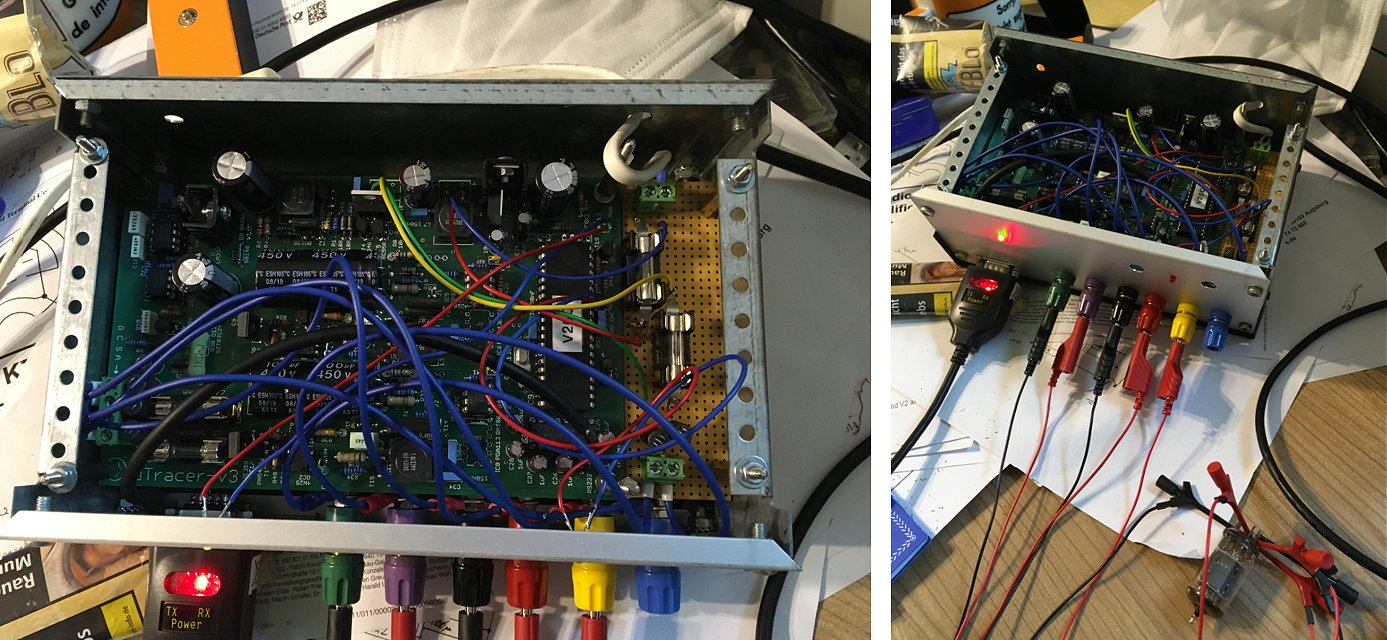
Moin!
Because I'm not the mechanic, it take a little to assemble a real device.
The pcb was finished in three days, in slowmode and enyoing it.
As you can see, I decided to do it with clamps instead of sockets.
And this is my first curve of the second half of an ECC83.
Also I attached two pictures, how I created the tracer.
With many thanks for that fantastic tool.
I'm going have new advantures with tubes.
Sincerely
Kai
8th of June 2020 Mark sent me a few picture of his finished uTracer!
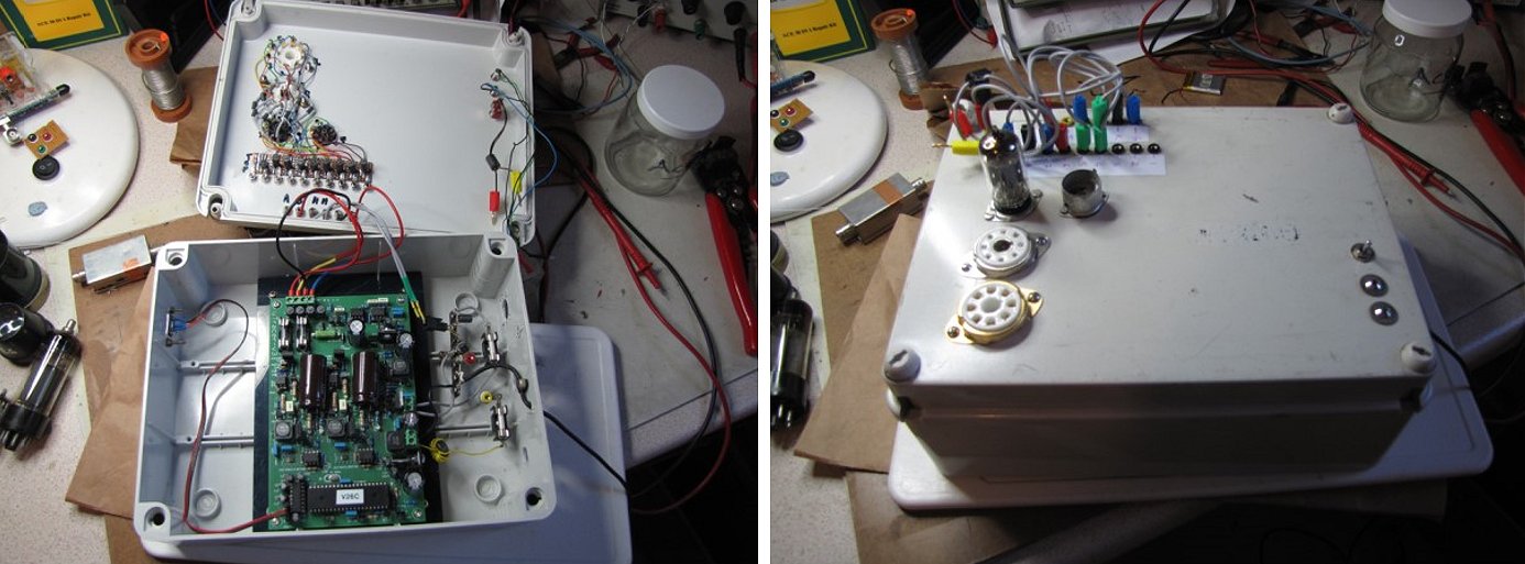
26th of May 2020 Ulrich Vogel finished his very compact and nice uTracer!
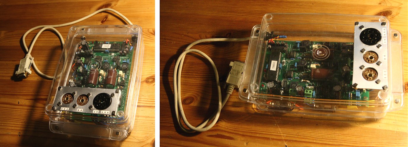
Hello again,
Finally i could finish my project and i have to say it was great fun to do so. Step by step with feelings of success every time. Great fun! Finishing the printed board took me around 8 hours, the casing 4 more. I took what was near my hands and it should be transparent, because the board is so nice to look at and the LEDs should be seen as well…. Because I just test the tubes of my guitar amps (some are hand build by me) and always wanted to match the final stage tubes by myself, this job can now be done (and has to be done soon :)).
You both are great people, I love your site and everything.
Many thanks
Ulrich
8th of May 2020 Heinrich Stummer posted an item on his very nice uTracer on his website!
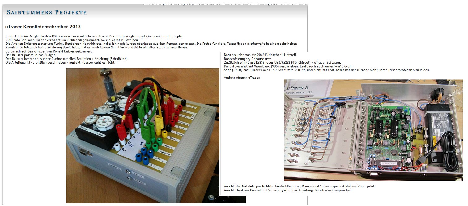
4th of May 2020 Michael Drexler from New York also used the lock down to complete his second (!) uTracer.
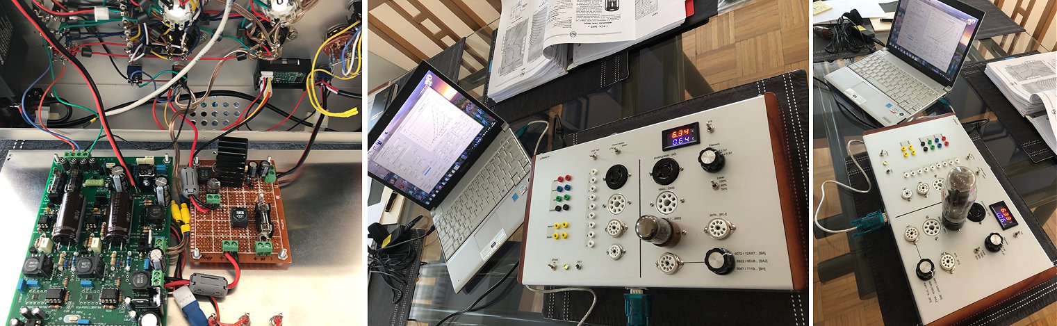
Dear Ronald (and Marie-Jose),
Greetings from New York, where the lockdown has afforded me a little indulgence — building a uTracer for my second apartment. Just like with my first one in 2014, construction was super easy thanks to the impeccable instruction manual!
External power supply is based on an LM2678 (handling up to 5A filament current) with a resistor network that allows for 50%/90%/100% voltage levels to do life tests (and for being gentle on firing up the valves under test). Pre-wired sockets on the right for the common types I use in my amplifiers, and free wired sockets on the left. The P/S selector and DHT switch combine to a) isolate the uTracer cathode lead when using the internal P/S on a DHT and b) connect valve-side cathode and heater for DHTs (as outlined in the user manual, section 8.14).
The wood-paneled enclosure is a 350x200x60mm size from doukmall on eBay — very good quality/looks and easy for the extensive metalwork needed. It should have (just) enough space inside to accommodate a uTracer v6 when it’s available. I am very excited by that prospect!
Photos below show some of the internals, and tracing a 5692 and 6B4G.
Thank you again for creating and evolving such a wonderful piece of equipment... us valve enthusiasts around the world cannot be grateful enough for what you do!
Hope you stay safe and healthy through those crazy times and well beyond!
All my best,
Michael
2nd of May 2020 Joe C finished his very nice uTracer!

First, thank you for such a well written and crafted kit. I'm happy to say there's another operational utracer 3+ in the wild. Also, Marie-Jose was most helpful and responsive in sending out a second PIC when the original was lost in the mail. Please send my appreciation.
-Joe
28th of April 2020 Thomas Emmer sent me a few beautiful sunny pictures of his splendid uTracer (and amplifier)!
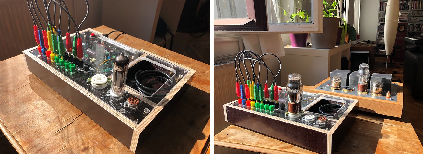
now that I have a lot of time at home I finally managed to finish the u-tracer which I used for quite a while now but without a proper enclosure.
Since this is done now I send you some pictures of it for your testimonial page.
I only use 3 different types of sockets as these are the tubes I am working with.
Thanks for the wonderful work you are doing, this really is an impressive piece of engineering!
Stay healthy and all the best from Vienna,
Thomas
28th of April 2020 Peter Weiss reports his uTracer working!
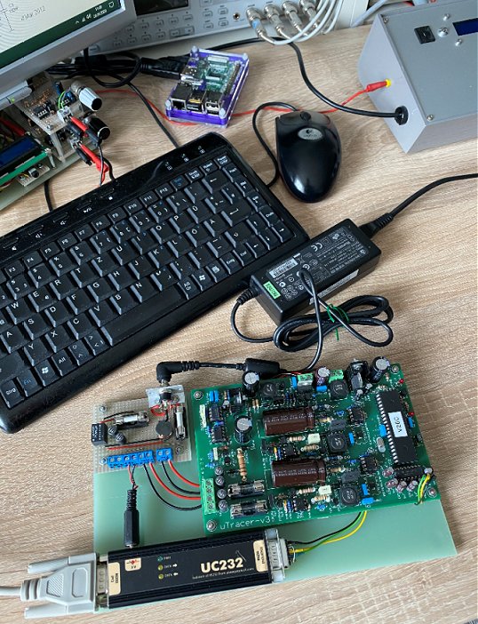
Dear Ronald,
The uTracer is really a very useful piece of electronic! It took me a while to assemble it, because I diverted from my usual practice to solder the whole board in one go, and instead followed your step-by-step advice. Really your extensive work for preparing the documentation and the excellent packaging of all the parts is very much appreciated! In my electronic life I build quite a lot of equipment, but never before I had seen such a well prepared kit! Many thanks for all your (collective) efforts!
At the beginning of my tube measurements I shot quite a few fuses (as you suggested, I put a T1.6A fuse between laptop supply and the uTracer), whenever I connected a scope. A look into the schematic showed why. I am now using an earthless laptop supply and connect my PC through an opto-coupled RS-232 device ;-) In the meantime I also learned that the easiest way of heating direct heating tubes is externally ;-) Everything is working fine now and no blowing fuses any more.
Thanks a lot for your time and all your efforts!! Greetings to your wife and a big thank you for all of her packaging!
Best regards,
Peter
27th of April 2020 Louis de Kort (PA3FTP) finished his very nice uTracer! Did I ever mention how much I like rotary switches!
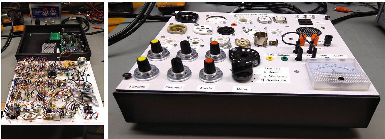
19th of April 2020 Illary Screm used the virus crisis to finish his uTracer!
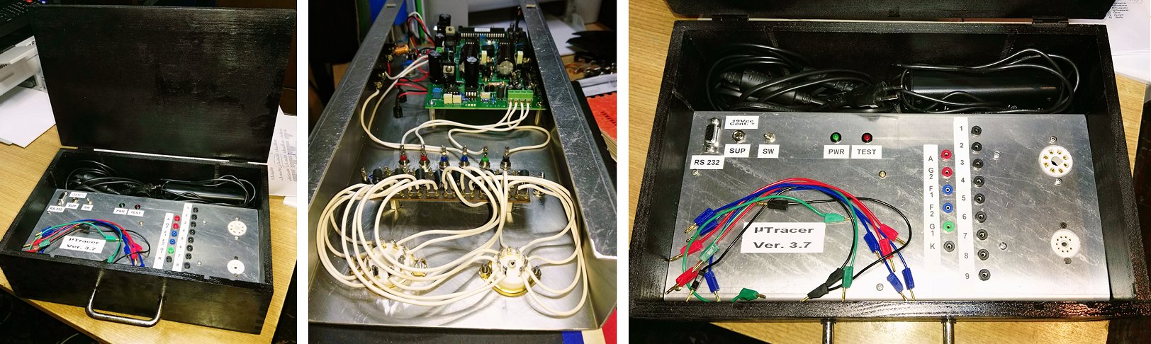
Hi Ronald and Marie José.
I took advantage of the days spent at home because of the epidemic to build my uTracer. Everything went well, it worked perfectly from the start. I have to congratulate you for the excellent work! I mainly use it to test audio tubes that I use in my amps. I wish you many beautiful things and further satisfactions in future works.
Greetings from Italy,
Illary Screm from Paularo (Friuli Venezia Giulia), Italy.
15th of April 2020 Ilia Vavilov finished his neat uTracer!
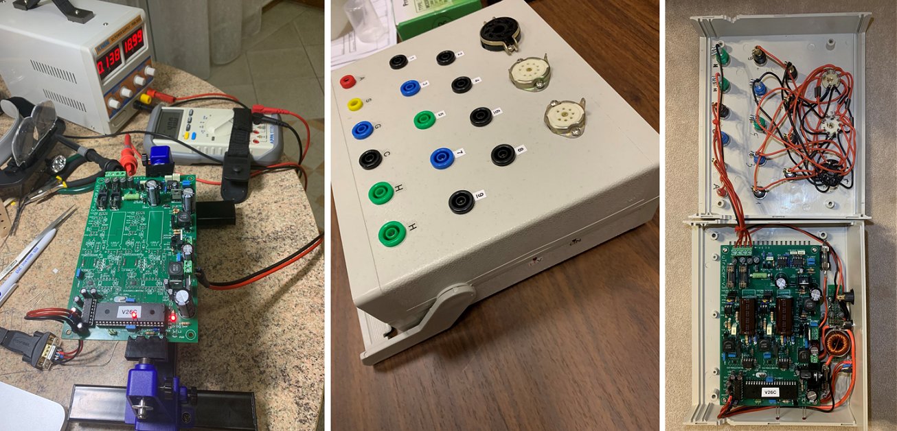
15th of April 2020 Andrew Prest is finishing his uTracer. Have a look at his amazing amplifier!
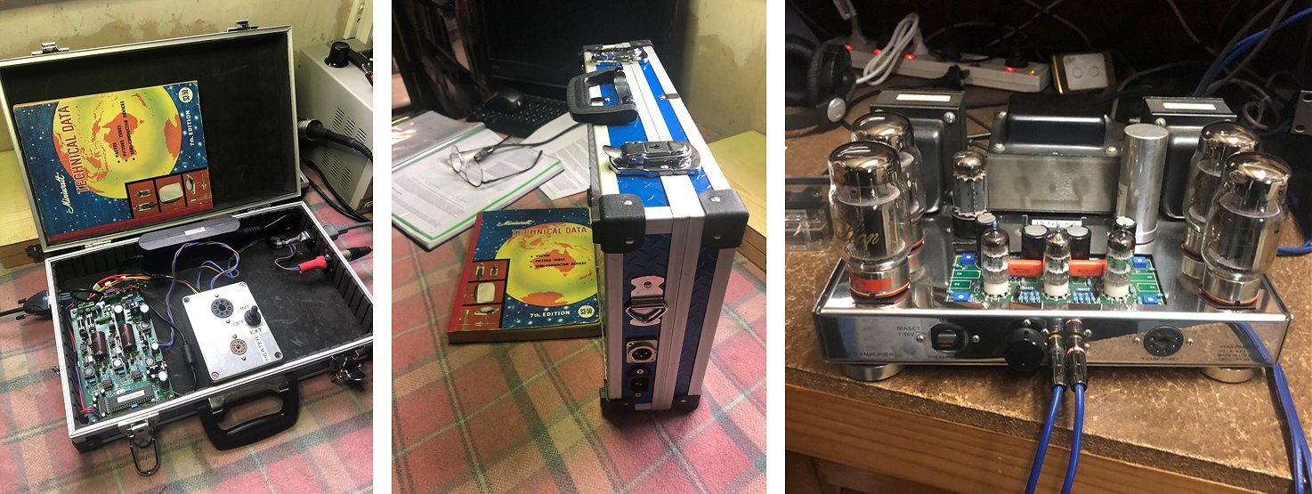
Hi Ronald , I hope this email finds you and your wife healthy , progress has been good with the u tracer especially due to the excellent assembly of the main board !!
The planning has been organic as being locked in my home due to the worst virus in our world’s living memory I made do with all the materials I had on hand , nothing has had to be purchased ( I love re purposing things anyway ) so far, but I do have some inductors arriving by post soon I have been especially pleased with my ability to trace twin triode performance and match this against original manufacturers specs.
I am still on a steep learning curve and now am trying to master the quick test mode , I included the Philips Miniwatt Australia book to show you where the data will come from ! Oh for the days where we made our own products and not everything came from China !!
There are still refinements to be made but at this stage I have all I need to master amplifier valves , it will grow from there !
Stay well
Andrew Prest
15th of April 2020 Jaska Niemi from Finland sent me some very nice pictures of his uTracer, … and of himself!
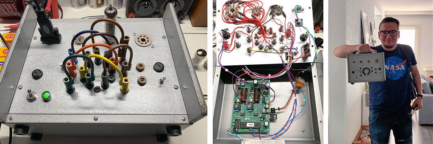
Hi Ronald & Marie-José,
I hope this e-mail finds you well. Now that we have to spend a lot of time home/indoors I finally had the chance to write you a testimonial about my uTracer3+ build and take some pictures. What a great kit! Very compact, quality components used and fast to build thanks to the comprehensive documentation.
The enclosure I salvaged from trash and made a new front panel out of composite aluminium. Sockets are Belton VT9-ST-2 and Belton VT8-ST (Micalex). Banana jacks are Pomona 1581-series and patch cables Pomona B-series (4"). Rest of the components are just what I had lying around in my workshop (power in is a XLR connector). Wiring is teflon insulated with high voltage/current ratings.
For layout I went for "Manning" style with internal/external heater and pulsed/continuous switches.
One socket is hardwired for ECC8x series tubes and the others can be patched with cables. I have a large collection of old ECC81, ECC82 and ECC83 tubes so having a hardwired socket speeds testing quite a bit :)
The build itself went without problems and only small "issues" with the completed unit is a quiet high-pitched inductor whine and regulators running quite warm. There's still room in the enclosure for a separate high-current buck regulator heater board or a cooling fan and I think I'll opt for cooling. Internal heater voltage can be calibrated with the help of external power supply and the latest software which is nice!
Being a mac user the software had to be installed with Parallels running Windows 10. I tried with Wine first but it wasn't stable enough. For the USB-C / RS232 cable I used Deltaco USBC-1103. One tip about using RS232 connectors: Outer shield is connected to uTracer ground, so if you have a metal case be careful not to short test points to the enclosure! Although it makes calibrating uTracer easy with the continuous mode modification :D
Attached are some pictures of measurements and test setup for a nice Philips QQE03/12 tetrode. And me with a backpack full of tubes heading to workshop!
Stay healthy and best regards from Finland,
Jaska
10th of April 2020 Christian Fromentin made a very impressive uTracer!
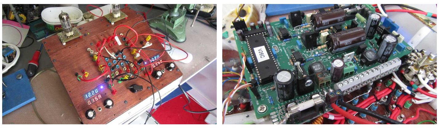
Hello, I am very pleased to see that the V6 project is progressing well. For my part, I finally finished what I started before I retired.
I preferred to use a separate heating supply realized with 2 modules with voltage and adjustable current. I added a device that gradually increases the heating voltage. There are therefore 3 power supplies of type pc portable, which allows me to have an electrical separation of the circuits. I also added a 4-way switch (VA,VS,Cathode and Grid). This allows me to test two tubes and also the 2 parts of ŕ double triode without being obliged to cut their heating or to de-wire.
I also slightly modified the routing of the mass plane which, in my opinion, created a loop all around the pcb. There is also a series of screw terminals to add extensions to the grid and anode voltage circuit.
There is also a USB/serial adapter and a serial isolator. The whole works perfectly and I thank you for this work.
I hope to read you again.
I hope the weather is as good at home as it is home in France (Brittany, Rennes).
Cordially,
Christian Fromentin
10th of April 2020 Petr Pacourek from the Czech Republic reports his uTracer working!
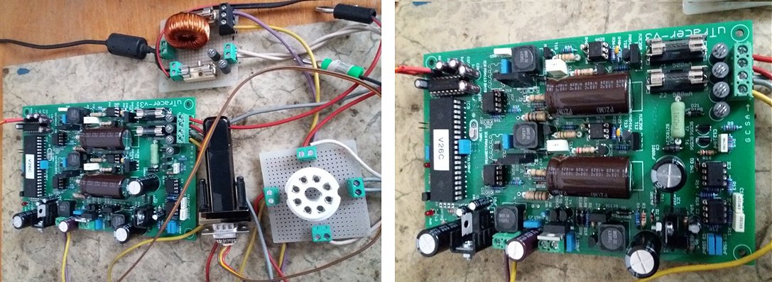
Hello Ronald and Marie-Jose,
sorry for the late reply.
My English is not good and I have to use translator.
I'm posting photos of my uTracer.
I am currently working on heater supply and case.
I use uTracer for measuring tubes when building amplifiers.
I am very pleased with other modifications and especially the newly developed uTracer V6.
I greatly appreciate your work on the uTracer project.
I look forward to more new information.
I wish you much success.
Best regards,
Petr Pacourek - Czech Republic.
<
7th of April 2020 Gerd Blom made a beautiful uTracer with rotary switches (I love those) and he wrote his own GUI!!
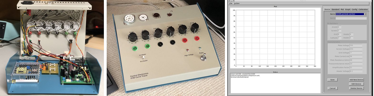
Hello Ronald,
Some photos of the uTracer I completed some months ago. The hardware which is working well is used with purpose written linux software.
Regards
Dipl.Ing. Gerd Blohm
Control Electronics Pty Ltd
Website: www.controlelectronics.com.au
5th of April 2020 Randy Evans sent me a few pictures of his uTracer. I am so impressed by his fantastic work bench!!
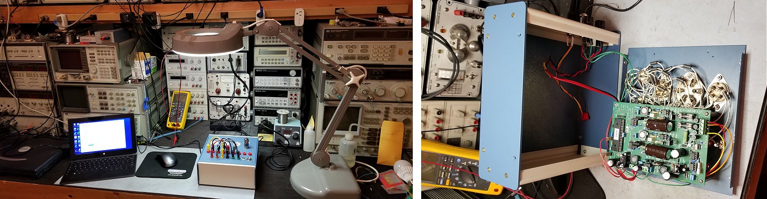
Ronald,
Attached are some pictures of the finished uTracer. It works great and it makes a nice addition to my work bench. I find it very easy to use but I have had a couple of occasions where it locks up and I have to unplug the PS and let it reset. I am thinking of adding a reset button since it takes several minutes for the PS voltage to drop low enough to reset the uP. What would you recommend for a reset function?
Regards,
Randall Evans
4th of April 2020 Robert Waldow uses the uTracer in his business! visit his website and the page about the uTracer.
Hello Marie-José & Ronald,
I'm very happy with your uTracer! A great protect an a really fine kit and software. To a fair price.
I like to ask is it allowed to display your uTracer and link it up to your website.
I generate a semiprofessionel website. I'm a one man show and offer service vor audio (100 Volt technic) and communication equipment (Stentofon). So I like to show a little from my audio hobby.
http://waldow.com/audio-hobby/tracer
Best regards
Robert
15th of March 2020 Jaime J. Díaz Tenreiro from beautiful A Coruńa in Galicia sent me an enthusiastic report on his uTracer!
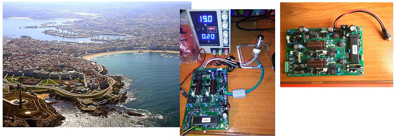
5th of March 2020 Jean-Yves Lévesque from Canada is ready to assemble is uTracer. Have a look at his fantastic lab!
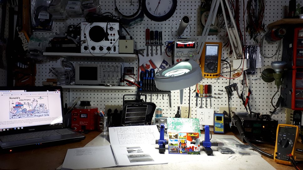
Hello Ronald and Marie-José,
Yesterday I received the kit and everything seems to be perfect! The kit is awesome!! Nicely packed, very nice and detailed construction manual and a separate schematic!!! Plus a beautiful French written Postcard!!! Hours of pleasure coming... I will take my time to enjoy the building!!!
Merci beaucoup!!!
Jean-Yves Lévesque
4th of March 2020 Have a look at Peter Doxat’s beautiful uTracer!
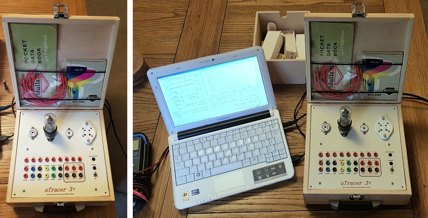
Hi Ronald,
I Just wanted to say thanks for such a well thought out kit, and excellent instructions!
I have just finished mine, and that means I can check through the valves I have acquired over the years, and also start the the rebuild of my 405 line Bush television from 1950.
Thanks again to you both for the excellent communication and support!
Kind Regards,
Peter Doxat
25th of February 2020 Richard Mak sent me a few pictures of his super uTracer!
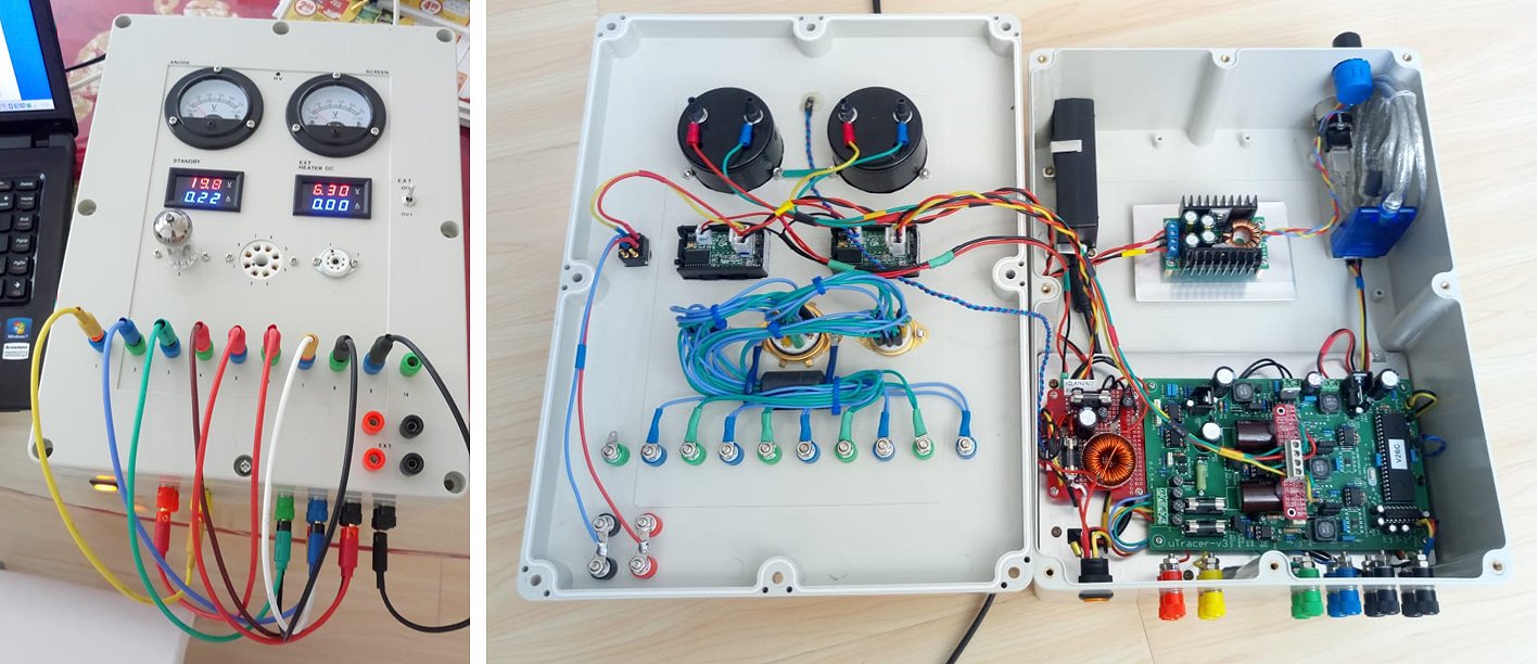
Hi,
Finally built my uTracer! Like what I build?
Great product!!
Cheers,
Richard Mak
21st of February 2020 Lennart Nilsson will use the uTracer in his tube test training!
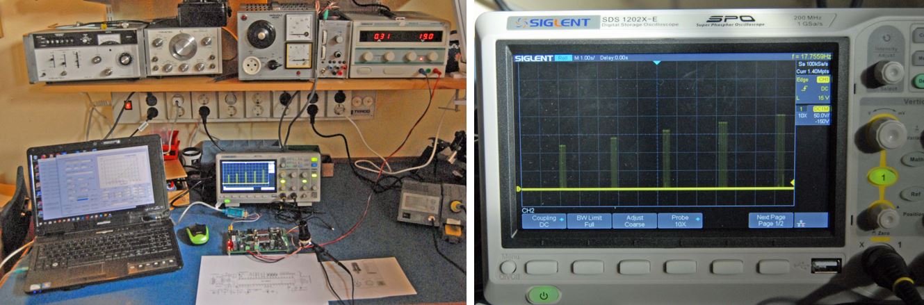
Hi Ronald and Marie-José
My uTracer made its first tube traces today! I enclose some pictures of my test setup.
Next job is to make the enclosure and socketadapters. I intend to make the socketadapters
100% compatible with the adapters of the Tektronix 570 curve tracer.
I would like to thank you very much for an extremely well designed kit and detailed instructions going with it! Very good idea to build and test the unit in parts, which makes it easier to find mistakes. Never the less I succeeded to make a couple of bad soldering joints which caused a strange error message in the GUI and made the high voltage led never go off. The problem was solved by careful inspection of soldering joints.
I think the uTracer will be of great use in my tube testing training I am going to give next month at the Gothenburg Radio museum. If you happen to visit Gothenburg, give me a note, and I will be happy to guide you through our enormous radio Collection (900 m2). https://wordpress.radiomuseet.se/
Best regards
Lennart Nilsson
13th of Fabruary 2020, Simon Murton sent me a picture of his uTracer in action!
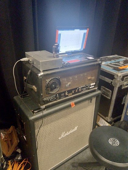
Hi Ronald,
attached pic of my uTracer at work For me, the issue is EL34 or 6550.
I have not installed noval sockets yet, but I intend to have separate for EF86 EL84 and dual triodes.
Regards Simon
5th of February 2020 José Martins used an old tube tester as “case” or his uTracer, brilliant!
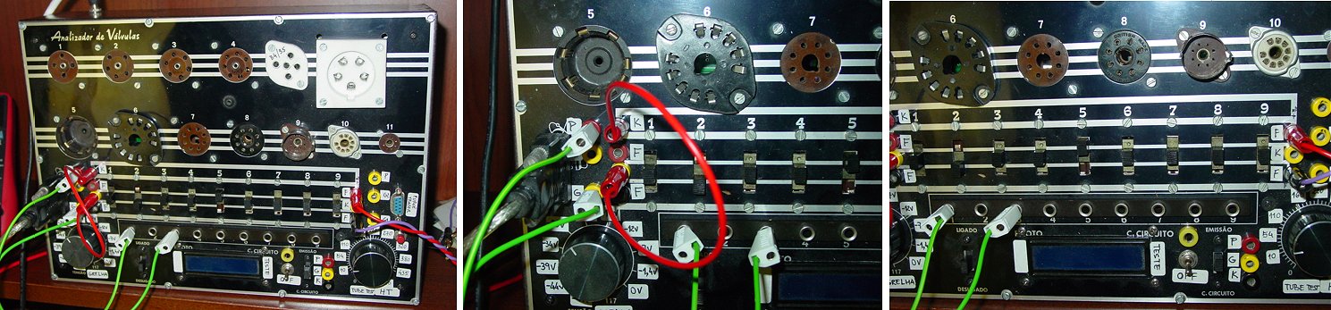
Hello Ronald Dekker,
Thank you for your e-mail with the news about new version of utracer6.
When this new uTracer 6 will be ready I’m interested in order one unit.
I still have your uTracer that I love very much but it is little limited to measure transmitting triodes and for the 300B.
I added some pictures of my uTracer that was installed in an old tube tester and works great. The filament supply came from an external variable power supply, because i test many DHT tubes.
Best Regards
José
5th of February 2020 Fabio Casagrande created a magnificent uTracer!
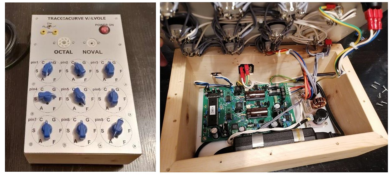
22nd of January 2020 Uwe Lehmann created a magnificent uTracer!
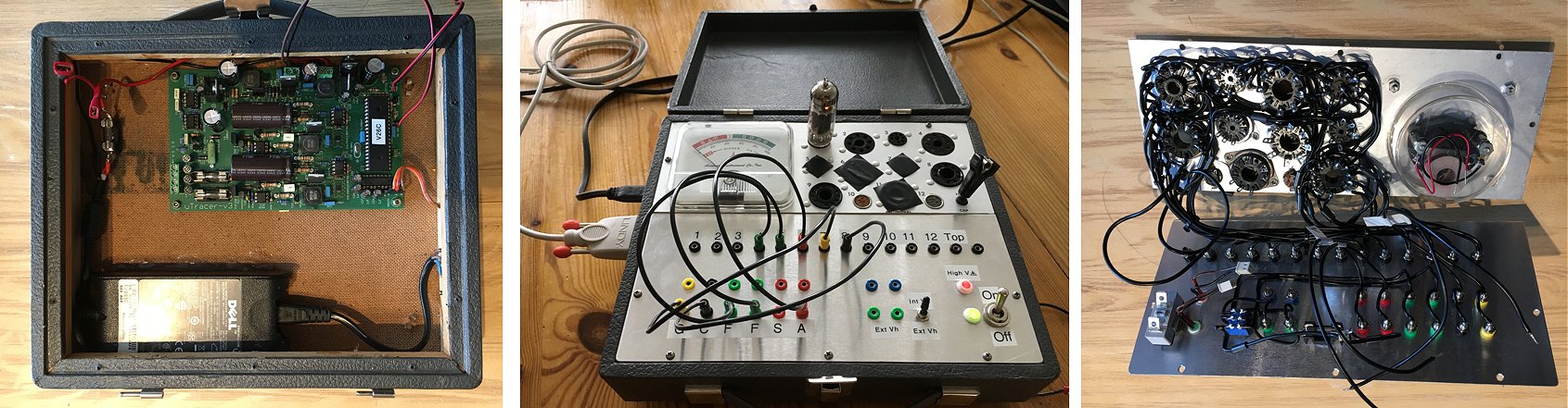
Hello Roland and Marie-José,
Now I found the time to assemble the µTracer 3+ I bought from you some time ago. And it works perfect, so I started to measure the first tubes of my HiFi amplifier V10 from T+A. It is a nice tool and thanks a lot for developing it. Please find attached some pictures showing the µTracer Board mounted in a "Tube Tester Model 157" from "Accurate Instrument Co. Inc.“ case. I used six of the tube socket's and the rest is for spare. The original gauge I’m currently not using and maybe I have to replace it by a vent soon. The last pictures sowing the µTracer in operation with a ECC99 tube. The Ia/Va curve of this tube is shown in the last picture. The next investment will be a µTracer 6 with higher current to characterize the power tubes EL509 if available.
Thanks a lot and all the best for you from Switzerland,
Uwe
13th of January 2020 Another beautiful uTracer saw the light. Thank you Kerry Gerontianos!
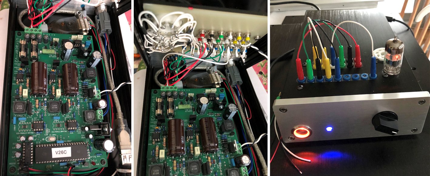
Hi Marie-Jose &Ronald,
I’ve finally gotten around to finalizing the case of the uTracer3+.
Here are a few pictures. Thanks to you and the forums which gave me some great ideas on how to case up the tester.
I’ve added an AB switch to the front for testing dual triode tubes and have moved the HV indicator to the front panel as well. I mounted a USB on the back and enclosed the RS-232 -> USB inside the chassis. For the power supply, I used a standard laptop supply from a Dell and also found an inlet jack for it that I mounted on the back of the chassis as well.
Thanks again,
Kerry
9th of January 2020 Tang Guanwei & Bao Changjun from Beijing, China send me a few pictures of their very nice uTracer!
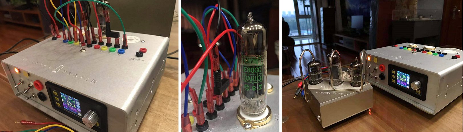
Dear Marie-José & Ronald,
First I want to wish you and all your family &friends a very happy and lucky new 2020 year!
I am a happy owner of your previously released Utracer from Beijing, CHINA.
Very excited and hopefully to see that finally you have made our dreams of a high voltage tube tester come true.
Nowadays I am starting to using a 845 PP high voltage amp to drive my speakers, so the old low voltage Utracer is able to test the small signal tubes(E182CC & ECC83)??but the matching and testing of 845 tubes is a big trouble for me.
Thank you for the news and looking forward to buy a new set of Utracer form you again.
I will find my time to send you my utracer photos ASAP, since I and my family are on a new year trip.
Best regards,
Bao Changjun & Tang Guanwei
6th of January 2020 I love the “back to basics” uTracer of Allesandro!
Click here to read more about Allesandro’s experience with the uTracer3 and other curve tracers on his one website.
5th of January 2020 Yes!!! the first round uTracer created by
József Sebestyén!
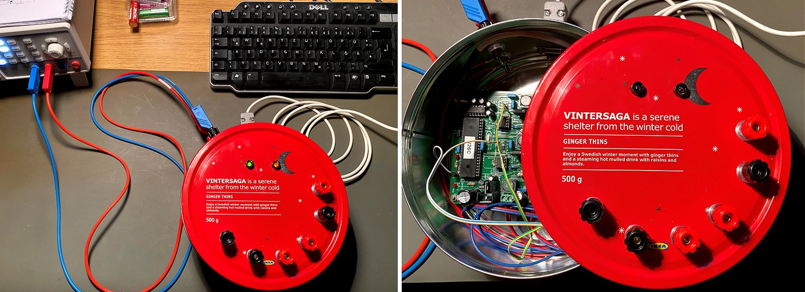
Hello Ronald,
First of all I want to thank you that you have published your beautiful uTracer project!!!
I have purchased the kit years ago, and after finalizing some more important family projects I decided to spend few days in this christmas-period for completing the unit. I red eagerly the very-detailed background documentation and based on that I built up and woke up the circuit. For first I have attached to it as a measuring head my old (own built) tube tester unit (as a tube-socket matrix). After some unsuccesful measurement now I now why the blody stuff was unstable (my old one, not the uTracer), thanks for deriving that as well!
Now all the bugs has been removed from the old socket-matrix, it got NOS Preh ceramic sockets and the whole measuring-unit is living at a real christmas-style housing!
As a travelling electrical engineer at the hotels during the boring evenings I will be able to analyze my tube-collection :) :) :) , because of the whole kit fits in an extra tool-box in my car!
Kindest Regards:
József Sebestyén
5th of January 2020 Richard Hoogeveen from
hmr-audio sent me a few pictures of his beautiful uTracer. I wish I could make something like that!

Hi Ron,
Ik heb hem al even klaar hoor, fijn apparaat, ik ben er erg blij mee. Ik kon er eindelijk mijn verzameling buizen mee testen en match ook regelmatig buizen als setjes voor push pull applicaties.
Ik heb de bovenplaat getekend in Fusion360 en gefreesd op mijn zelfbouw open portaalfrees. Het is nu een aluminium koffertje om de Utracer+ en randbenodigdheden te herbergen.
Ik ga je nieuwe ontwerp volgen !
Richard Hoogeveen
Zoetermeer
http://www.hmr-audio.nl
5th of January 2020 Peter Loster already sent me pictures of his beautiful uTracer in 2015 but I missed them!!! So here they are at last!
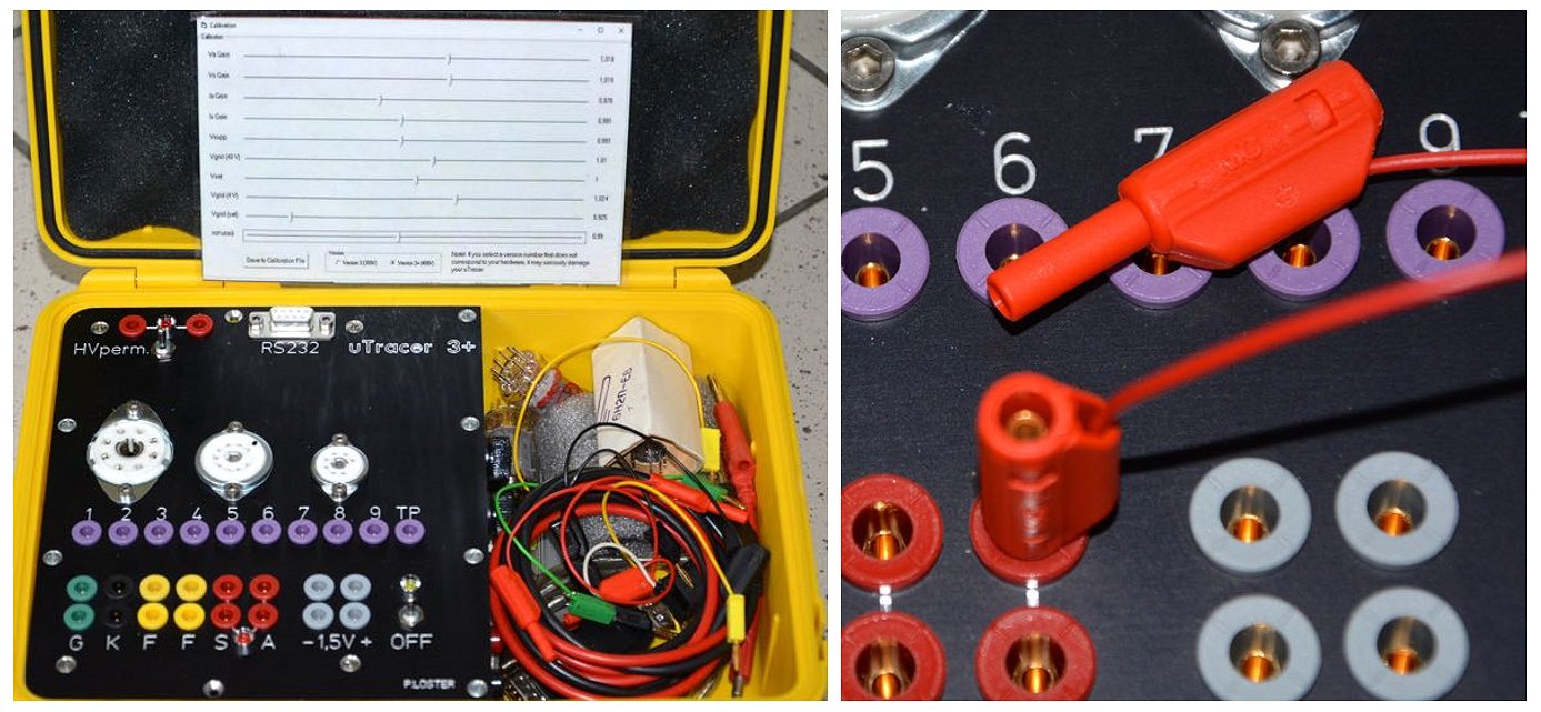
Dear Ronald,
thank you for the uTracer3+ which helped me a lot. Building and setting-to-work was fun following the good instructions. It was built into a standard plastic case as shown in the pictures. To be a better protection from high voltages I used the small banana-style plugs with protection tube. The front was ordered from a front-cover design company using the software frontDesigner. The PCB was mounted underneath using 15mm high spacers. Thank you also for your frequent update information.
1st of January 2020 Federico Paoletti from Italy used the Christmas holidays to finish his very nice and well connected uTracer!
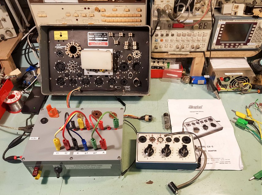
Hello Ronald,
years ago (maybe in 2016, I don't remember) I bought from you a uTracer 3+ . And you asked to send a picture of my setup. Until now I've used your uTracer as a "board", testing only a bunch of Tesla E83CC "cross swords" I had in my basement since many years. Now, profiting of these holidays, I've dared to put it in a box. Attached the picture.
Also, as you can see, I have (and now use!) a couple of extensions: one is part of an old AVO CT-160 tube tester, the other one is a CA-5 Hickok adapter. Total sockets number is now about 30.
When using the three sockets permanently attached on the uTracer box, I can use the heater value previously computed and saved in the uts files; if I use the small CA-5 adapter, the error is negligible; but when I use the AVO CT-160 I'm forced to use an external DC power supply: the wires inductance is too high.
BTW a good tune procedure for the heater value is the one you suggested (comparison of traces with internal/external power supply), in that case is better to use a "old/used/tired" power tube (e.g. EL34), that is more sensitive to the heater value.
I hope that you'll came out with the (in)famous V4 version (higher voltage and current, without sacrifice the resolution at low values). The best would be as a "plug-in" kit, in order to continue using the old 3+
All the best
Federico Paoletti - ITALY
22nd of December 2019 Juan from Spain finished his very pretty uTracer just before Christmas!
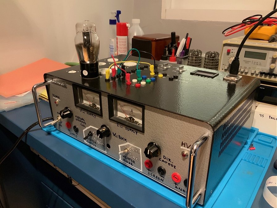
Hi Ronald and María José:
First of all congratulations for your excellent kit to trace tube curves! Finally, I have finished the case of the utracer recycling the chassis of an old lab power supply. Thanks for your work! I have attached a photo showing the utracer and the “fresh lettering” hand made!
Regards from Spain!
Juan
18th of December 2019, Ted Walker sent me a picture of his very nice and transparent uTracer!
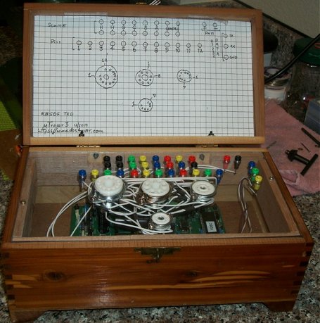
Hi Ron,
I have installed my uTracer 3 in a cedar box, photo attached. I'm looking for a program to make the index look more professional. The box is ~10" x 5.5" x 4.75" high. I chose Lexan instead of plexiglass for it's superior strength and ease of drilling. I chose the clear panel so we can see the inner workings AND the leds. I used 2mm banana jacks throughout and use an external power supply. There is room to add more sockets but for now if need arises, I will use an external circuit board mounted socket off to one side. Now to put it to work.
Thanks again for making this tester possible!
Thanks for your site and all that you share!
Ted Walker
1st of December 2019 Bertrand cased his uTracer and he is rather pleased with it.
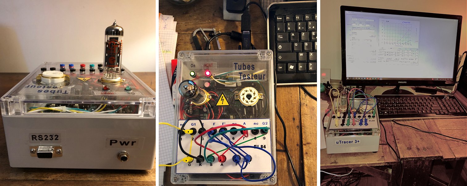
Dear Ronald
I’ve just finished the complete realization of the utracer3 +. So, you can add +1 to the counter of your "customers" who have chosen your utracer3 rather than another.
For me, I wanted to start this assembly to test the tubes that I use in my guitar tube amplifier (12AX7-EL84) and it is mainly with noval supports but maybe also octal tubes in the future for other Amps (EL34-6V6..). I found my plastic case at Reichelt, it is by looking the different utracer achievements already made that I found sympathetic these case transparent and good quality. I now had to go more to the test phase of the lamps in my possession and learn how to handle the utracer better.
Thank you for this ingenious invention.
Best Regards
Bertrand
from Paris – FRANCE - 1er December 2019.
1st of September 2019 Carlos Pechiar reports his uTracer working and on-spec!
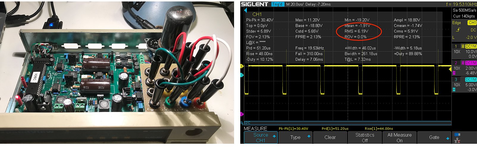
Hello,
I send more pictures as I progress on learning how to use the tracer.
As a first impression is that this device is really good!!
The first picture is the actual state of my unit testing a 6V6 tube. Pin routing is done with jumpers.
The second one, which can be interesting, is a screenshot of the filament voltage waveform. In the measurement data of the scope, RMS value can be seen to be very close to 6.3 V.
Regards, Carlos.
13th of July 2019 Steve Lyons sent me a picture of his very nice and compact uTracer!
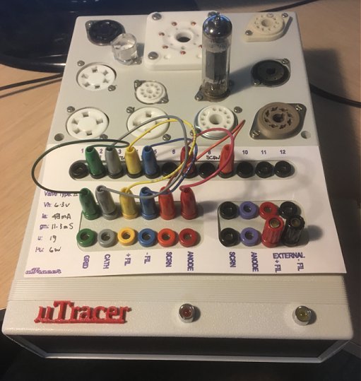
Hi Ronald,
Finally getting around to reporting on the success of the U-tracer project.
I ordered it last October and the kit arrived within one week to my place here in Canada. That was incredibly fast and left me floundering around for valve sockets and hardware.
I built the kit and had it completed by the end of October. I found the kit to be very well organized and accurate. The instructions are well written leaving nothing to ponder.
The completed and calibrated board assembly was put in a plastic enclosure with some of the assembly suggestions you provided. (Banana Jacks and such) I used my Silhouette cutter to make valve cards similar to another suggestion you had and added a generic inscription to enable connecting the jacks up accurately.
I created a 3D file of "U Tracer", printed it out and glued it to the front face of the enclosure.
I might add an analog meter to the front of the enclosure to measure plate current and heater current.
That's it for now.
Thank-you for providing a very well-engineered kit as well as deep technical information on your website.
Best regards,
Steve
7th of July 2019 Jim Ellington “packaged” his uTracer in an old Fender harmonica case
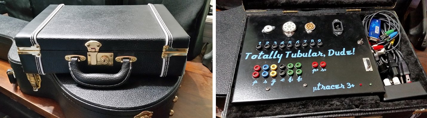
Hi Guys,
The build took me longer than I had expected. The tracer runs great!
Eye tubes look fantastic stepping through set points.
I have discovered some of the “matched” tubes in one of my amps are only matched at the sellers test point. Curves are not matched.
Bluetooth is really nice. My tracer is packaged in a Fender harmonica case. Too bad I scuffed the paint.
How many kits have you sold? Good kit, good project!
Thanks,
Jim.
19th of June 2019 Bert van Lelieveld sent me a few pictures of his nostalgic looking uTracer!
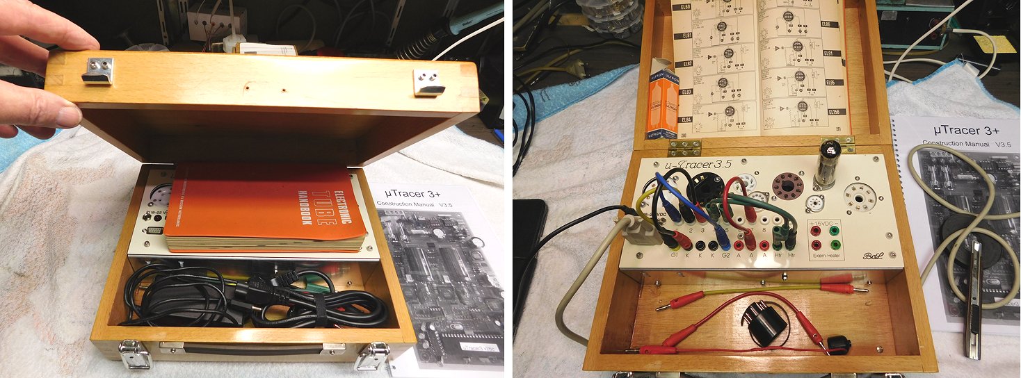
19th of June 2019 Harri Lumme finished his beautiful compact uTracer and even did a write up on his blog page!
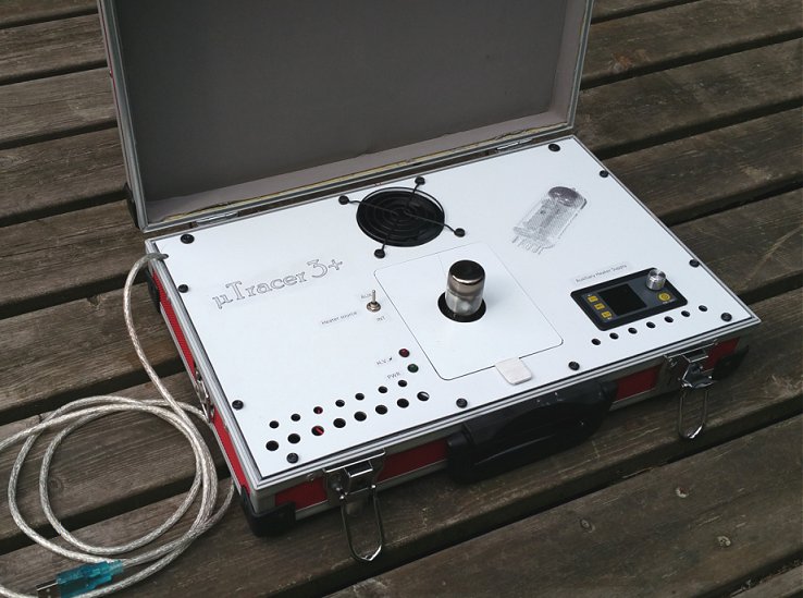
Dear Marie-José and Ronald,
I am happy to announce the kind of finish of my uTracer construction project. As I told before the assembling of the kit was so easy thanks to your meticulous design and instruction book drafting.
I had no hurry in building the case for the tracer. I actually had most urgent measurements done with the bare PCB and took my time to test ideas for the case design.
I aimed to a simple and clean result and I feel that my original ideas were well translated in the actual case design. My only regret is that the result still is unmistakably second-class home-brew. Luckily this is not a show piece and the only reason I enclose the image is, that maybe someone can still appreciate some of the features in my personal design and maybe even develop further some ideas.
I even produced some blog pages of my project if someone wants to see details of my work.
The summer here in northern Finland has started and the nights are so short that it is very difficult to see any glow in the cathode filaments. This is however the best time to do the case restoration jobs of old radios.
Wishing you and all uTracer users a very nice summer.
Harri, OH8SM
9th of June 2019 Stephen Lafferty wrote a beautiful review article for his website and included the design of a high precision heater supply!!
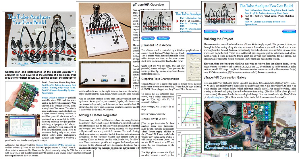
6th of June 2019 Norman Braithwaite finished his uTracer and he made a nice post of it on the Antique Radios forum.
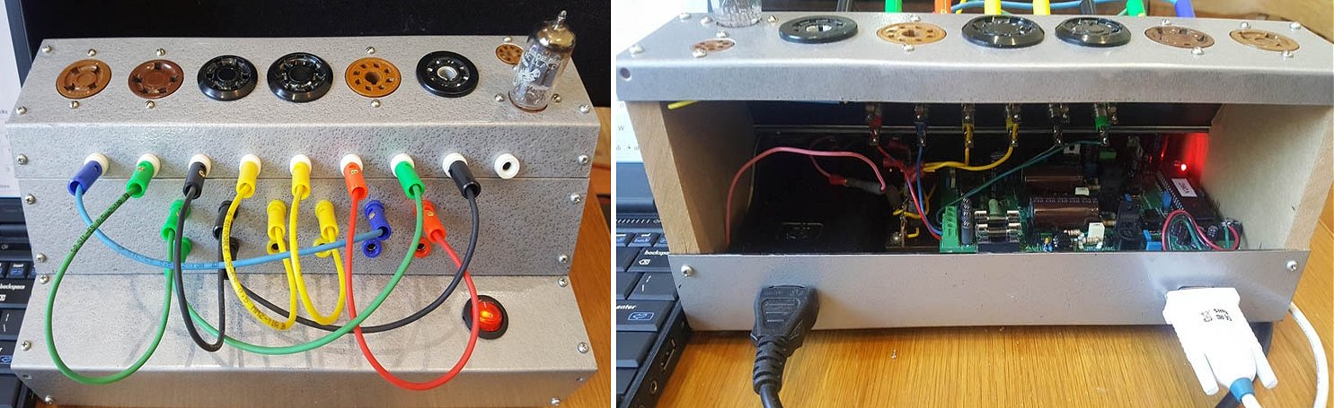
5th of June 2019 Dan Davenport from LaLuna Technology posted a few pictures of his great uTracer on his website.
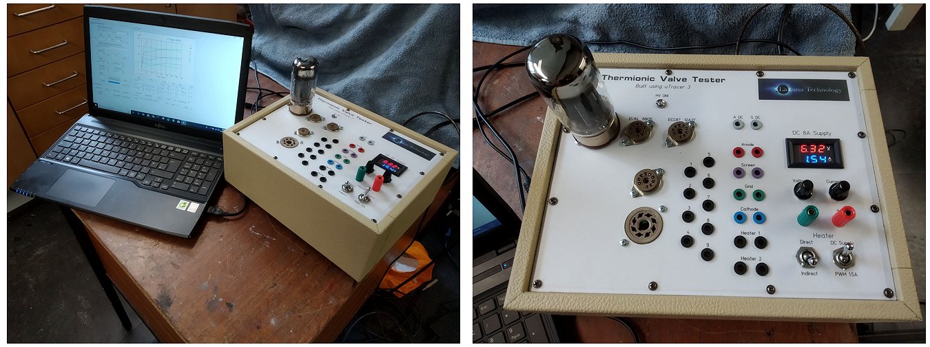
5th of June 2019 Edmond Verrijn Stuart turned his uTracer into a beautiful instrument and he added a true RMS converter (Click Here).
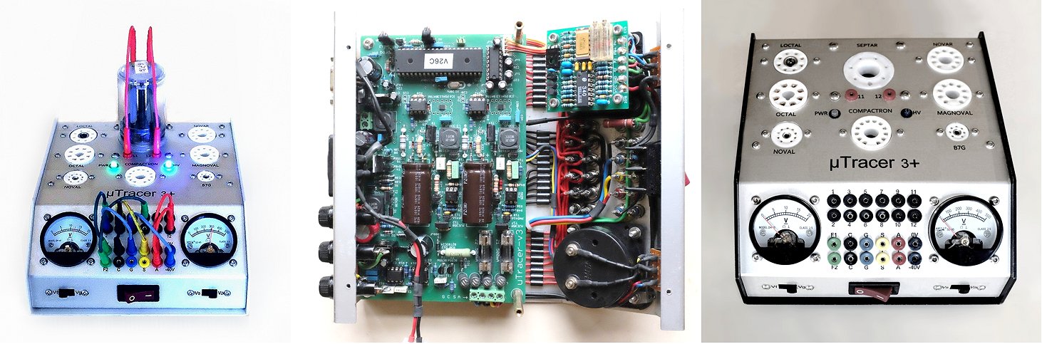
28th of April 2019 I love Steve Larkowski’s uTracer because of its sturdy look!
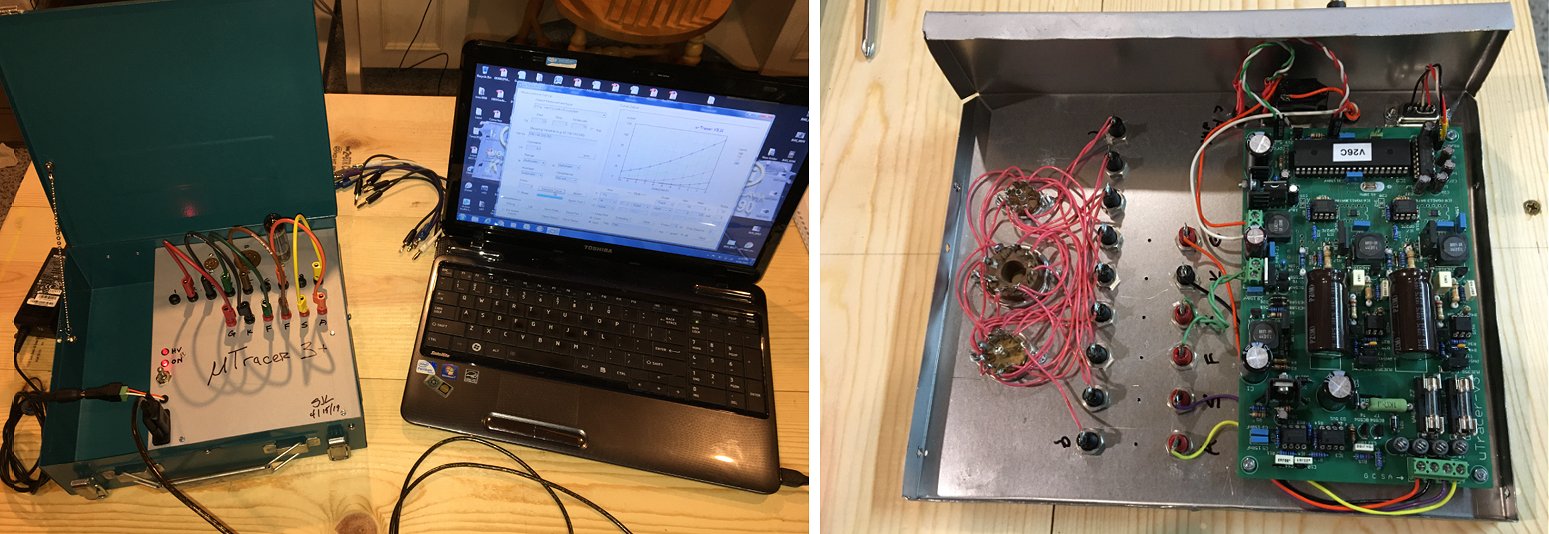
Ronald and Marie-Jose
Thanks for making this board available. I was able to finish up the kit and have been trying to figure out the different test modes in the software. The manual was very well written and helped me thru the build process. I have included some photos of the finished product, it may not be as pretty as some of the kits you have shown on your website, but it is functional. I used an old drill box as the case, I think it worked out quite nicely.
Thanks Steve
21th of April 2019 Harry’s uTracer is beautiful and very compact!
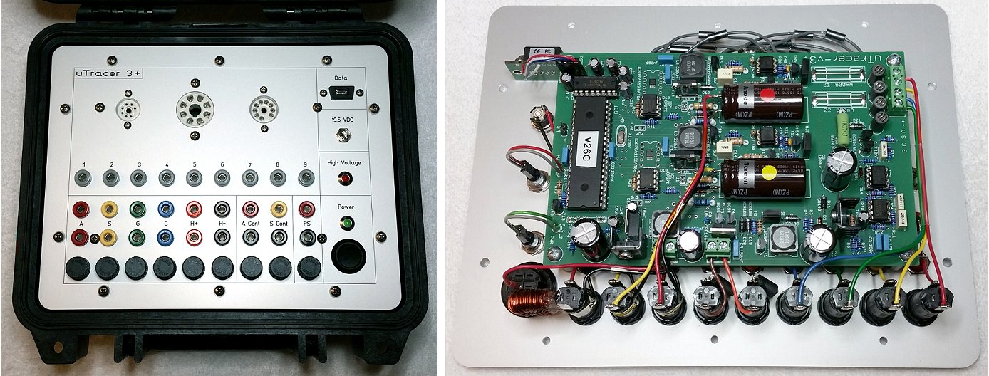
Hello,
I just finished my uTracer today. The kit itself went together very quickly, but it took a while to figure out how I wanted to enclose it. I wound up using a Pelican 1200 case and having the panel made by Front Panel Express. I'm quite pleased with how it finally turned out. I did fuse all the lines just in case, although I'm still working out some of the fuse ratings.
Thank you for your hard work in producing a nice piece of test equipment.
Harry
6th of April 2019 Dutrach’s beautiful uTracer with a matrix connection reminds me of the Neuberger RP270/1 I saw in my youth.
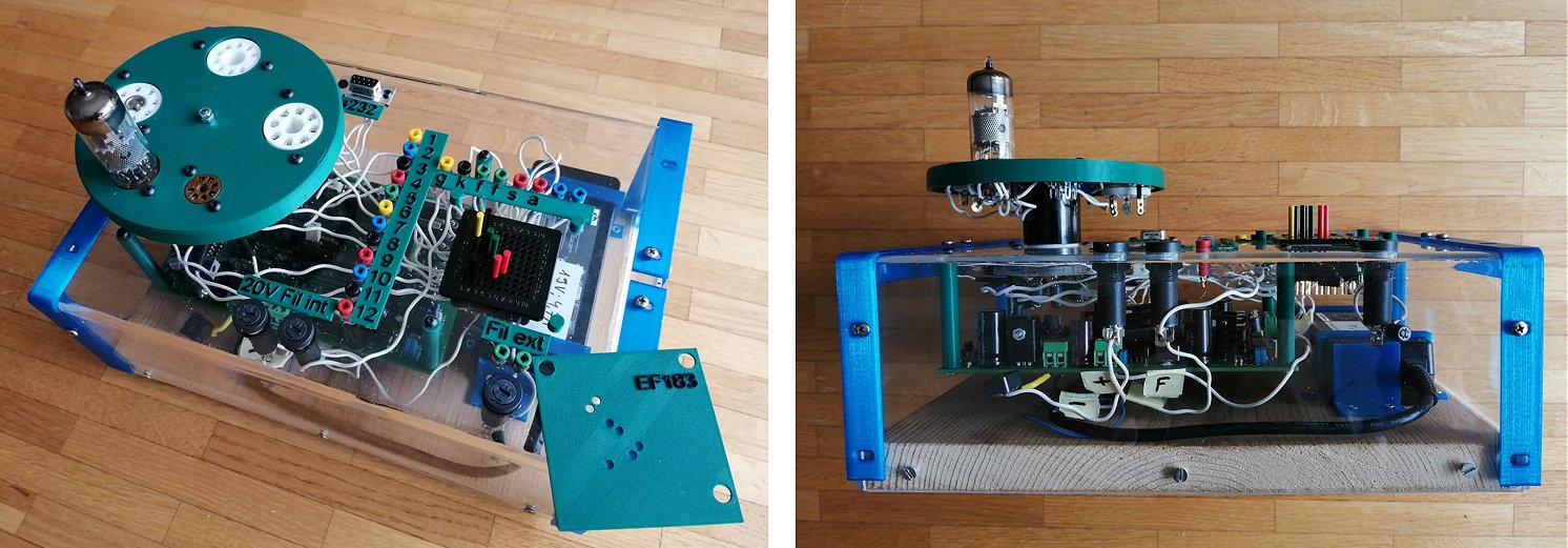
Hello Marie-José and Ronald
Thanks again for your construction manual. I was quite impressed by the level of details. I really appreciated the different sections about testing. It would have been difficult to find out problems if all components were soldered in one go!
I finally managed to complete my uTracer 3+. That was an interesting project and a good way to learn about vacuum tubes. As you can see on the pictures, items in blue and green have all been printed on my home based 3d printer. The acrylic case has been formed with a hot gun.
To connect the utracer board to the different tubes, I use a 10x10 matrix board. I 3dprinted different templates for different types of tubes. I just overlay the template over the matrix and connect the pins in the predefined holes...no more errors! The tubes sockets are mounted on a support (3d printed as well) and the support is connected to the acrylic case via a 12 pins compactron socket (B12C) extended by a Compactron test socket adapter (model TVS-12). That one was quite hard to find!
The 2mm. sockets are there to first verify the correctness of the templates (check the connections with an ohmmeter) and to add a possibility to connect the tubes directly to the board (skipping the matrix for whatever reasons).
That's completed the project. Next one will be to build an audio amplifier with these tubes that have been lying around for decades!
6th of March 2019 Philippe Canat sent me some nice pictures of his beautiful compact uTracer!
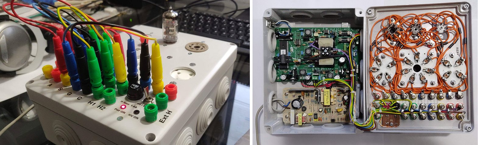
Hi Marie-Josée & Ronald
I hope you are well.
At last, I finished building my uTracer a few days ago and successfully tested a few nine pins tubes. It is working great, this is a very helpful & handy tool you conceived here!
Concerning the build, it was a very smooth & easy to go with process ! The building manual was a huge part of that success, you did a very nice job with that too, congratulations!
RS232 link is working fine on my desktop PC; for my laptop a cheap CH340 RS232 to USB adapter does the job just as well! I might play with some RS232 to Bluetooth adapters in the future, but I have no real need for that at the moment.
As a told you in a previous email, I did not have a used laptop powersupply on hand, thus instead I used an old HP printer power supply, 18V / 1.1A, with very good components onboard, such as Nichicon caps ! It is working great with the uTracer & its power output has been proved to be ok until now, alleged by a successful short 14.5V & 1.6A heater circuit test session ! Since that, I saw other users had build their uTracer with that specific supply, which seems to be a very common one, since those HP printers were and still are very cheap. (On the other side HP Ink cartridges are a total steal, but that is not the debate here...)
The 330uH inductance I used for the power supply is the Vishay IHD3EB331L, mounted on a perf board, with the PS fuse holder.
I put a little board on top of the mains caps, in order to fit a connector for the two additional "DC" connections. I installed a set of connectors for external heater supply on the top panel, alongside with a switch to commute between internal & external heater supply The fuse holder for internal heater supply has been mounted on the top panel, alongside with the PWR& HV LEDs. I used a cheap but quite sturdy electrical junction box for the enclosure, which does the job just fine.
Concerning tube sockets, I installed the usual 7, 8 & 9 pins ones, along some bigger ceramic 4, 5 & 7 pins ones (for 807, 300B...), which i have no use for at the moment, but who knows...
Concerning the tubes I tested :
- 12AX7 (cheap Chinese one) : both individual triode curves do not quite match but I had no expectations with that one ! Being able to test both triodes at once is a nice feature to have!
- EL84 (EH) : interesting to test the whole -15=> 0V grid bias range, with Va & Vs (Vg2 here) constant, then again with Vs variable. (CF attached plots)
- EM84 (cheap Chinese magic eye) : A little harder to deal with at first, but quite fun to play with ! I used the "DC" Anode & Screen outputs of my Tracer, of course.
- UY85 : Rectifier used mainly on serial filament heaters vintage radios : It does need 38V & 100mA on the heater side, so I used a 12V PS with a cheap adjustable boost converter (up to 50v), via the external heater inputs of my tracer, it worked like a charm!
Again, thank you for this great tool!
I strongly recommend it to electronic hobbyists like me, already experimented with modern electronics at some degree, but who also want to get a deeper understanding of vacuum tubes !
Please find a few pics attached, and feel free to add those along with this testimony on your website.
Thanks again
Best regards
Philippe C.
3rd of March 2019 Charles Murray finished and tested his beautiful uTracer!
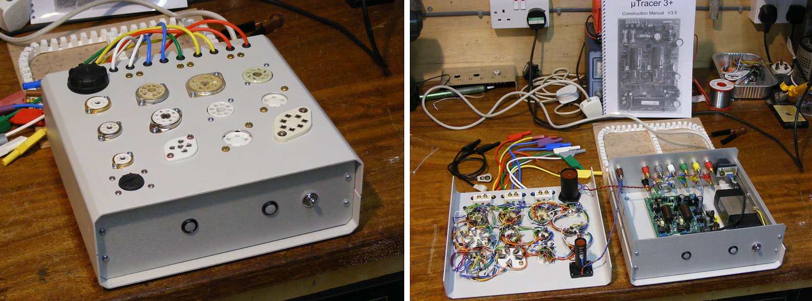
Hi Ronald & Marie-José,
Finally the curve tracer kit you sent be last May is now complete and operational. Photo DSCF5100 (attached) illustrates the completed curve tracer.
The valve holders are all ceramic, chosen in order to minimise leakage. These proved quite tricky to get hold of and the Mazda I.O socket was supplied as a N.O.S ceramic insert without any mounting. I made a mounting from from brass for this, copying one form a similar standard I.O valve holder I had to hand. Most of the holders were unused N.O.S or modern copies produced in China, and two were second-hand which I had previously salvaged. These were very carefully cleaned using a baking soda solution in an ultrasonic cleaner (great for removing carbon and burnt on dust deposits) followed by thoroughly de-soldering cleaning and re-tinning the terminals. The hardest part of the project was wiring the valve-holders. Originally I made a template (which can be seen to the rear of the curve tracer in the photos) with every intention of producing a neat cable loom. In practice it proved virtually impossible to keep the length of wire from socket to socket and in each loop identical (as per the AVO patent Ron mentions in the instruction book). This idea was subsequently abandoned, and I decided to take the back off my old AVO MKIV valve tester to see how AVO had wired their sockets. What I saw was an untidy “Birds nest” of wiring! – exactly what I was trying to avoid. In practice however this is the only way - as can be seen in photo DSCF5099. I have used different ferrite beads than those recommended and have fitted a bead over each wire between sockets and loop termination points with 14 beads per loop.
I also added two battery holders, one holds a D cell, to provide a 1.5V filament supply for directly heated valves such as DAF91 for example, and a AA battery holder which conveniently holds two 4xLR44 6V batteries to provide a 12V supply. The 12V supply is intended to offset the grid supply to allow measurements to be made with positive grid bias (using a bench DMM to measure grid current).
The computer interface (Top Right) is a “Brainbox” US-159 isolated USB to RS232 interface, providing a galvanic-ally isolated USB connection to my PC.
Next steps – To modify the curve tracer for higher currents following Ron’s recent guidance – this will help in regard to measuring valves such as the EL34 under conditions of positive grid current.
Overall an excellent project with a very good construction manual.
You are most welcome to publish this on your website.
Kind regards,
Charles Murray
1st of March 2019 Patrice Taillandier took some time to finish his uTracer, but now it looks fantastic!
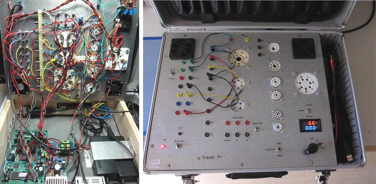
Hello Ronald, Hello Marie José,
I am happy to bring you some news of my µTracer.
I have not been very quick at building this excellent device, but it is finished and has been calibrated at the end of the year 2018.
I must recognise that your kit is the best I have ever seen in my life, particularly with the building manual.
Step by step building and step by step checking invariably leads to success to get a functional measuring instrument.
I was happy at the end of 2017 when I reached this stage and could make the first measurements with only the card on the table.
Then after reading the testimonial page, I made a choice to implement this card in its final housing and I choosed to put myself in the footsteps of Paul Newman
whose solution seemed very convenient for me, as you can see on the pictures.
But I was very slow in doing that and only milled the main plate in the summer of 2018, and made the full assembly and wiring at the end of 2018.
I am now very happy with this tool even making measurements or sorting tubes for myself and for friends.
I could not make without this instrument that became indispensable to me in my own lab.
I really thank you for giving us such a great achievement. I read carefully all your updates. I did some and I think for others.
Happy to red you again.
Best regards
Patrice TAILLANDIER
24th of February 2019 Martin Rauscher finished his uTracer and added a leak tester!
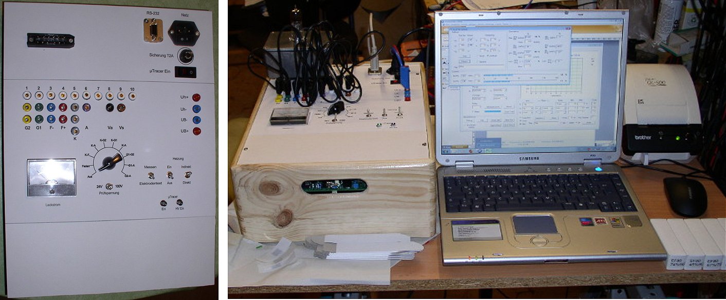
Dear Ronald,
now my µTracer is finished and works!
I've added a circuit to test the insulation between the electrodes of the valves.
For more information please note the schematic attached.
I've attached two photos also.
One of them shows the µTracer in action while testing EF80 tubes.
Best regards
Martin
20th of February 2019 Bert Groeneweg made a beautiful compact uTracer (in Dutch)!
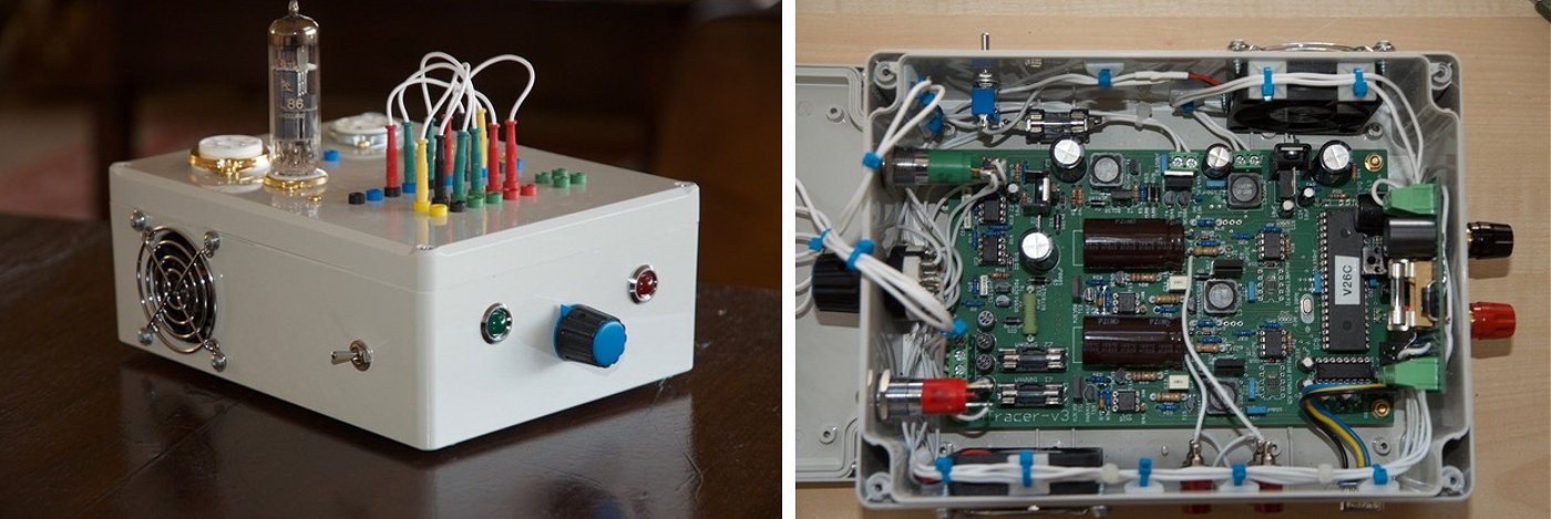
Beste Marie-José en Ronald,
Hierbij het eindresultaat van de door mij gebouwde uTracer. Allereerst ben ik op zoek gegaan naar en bruikbare kast. Dat is tegenwoordig lastig en al snel kostbaar. Uiteindelijk heb ik gekozen voor een Bopla kastje (rond de 20 euro bij Reichelt) van 200x150x78 mm (lxbxh). Dit is een waterdicht kastje, met een wanddikte van 3mm. Om toch voldoende ventilatie te krijgen heb ik 2 12V fans (1 inlaat, 1 uitlaat) gemonteerd die ik nog had liggen in mijn “junkbox”. Met een drie standen draaischakelaar op het front heb ik nu de volgende mogelijkheden:
Stand 1: fans in serie op 12V (nauwelijks hoorbaar)
Stand 2: fans in serie op 19V (merkbaar luider nog niet irritant)
Stand 3: fans parallel op 12 V (irritant maar voor de tegenwoordige hete zomers wel handig)
In de praktijk lijkt stand 1 voldoende. Met de schakelaar aan de zijkant kunnen de fans worden uitgeschakeld om eventuele beďnvloeding van de metingen te voorkomen (echter niet merkbaar).
Ik heb besloten om het geheel te voeden uit een van mijn lab-voedingen via bananenplug aansluitingen op de achterkant. Dit gaf mij de mogelijkheid om hierop een gaatjes print te monteren. Dit printje voorziet o.a. in de 12V voor de fans en de 12V leds met ingebouwde voorschakel weerstand op de voorkant. (Zie bijgevoegd schema). De High Voltage Led op de voorkant wordt geschakeld met een darlington transistor BD675 en direct aangesloten op RB5 van de microprocessor . De i/o poorten van de microprocessor mogen volgens de specs maximaal 25 mA leveren. De BD675 en T19-BC548 op uTracer print belasten RB5 met niet meer dan 1,5 mA, dus dit mag geen probleem zijn.
Ik heb gekozen voor slechts 4 voor mij belangrijke typen buisvoeten. Verdere uitbreidingen van buisvoeten zijn mogelijk door een apart kleiner kastje boven op de uTracer te plaatsen (zie foto) en via de zijkant van het kastje aan te sluiten zodat de aansluitingen kort kunnen blijven.
Ik had nog 2 buizen liggen een ECC83 en een ECL86, waarmee ik als 14 jarige (inmiddels ben ik 71) een rechtuit ontvanger met een Amroh 402 spoel voor de middengolf heb gebouwd. Na al die tijd zijn deze buisjes nog steeds in orde, ongelooflijk, zie de bijgevoegde uTracer metingen. Het geheel werkt fantastisch en de meetresultaten zijn reproduceerbaar. Ik heb er een prachtig nieuw instrument bij ! Ik ga mij nu verder verdiepen in de software en verdere mogelijkheden van de uTracer.
Ik hoop dat het geheel je goedkeuring kan wegdragen.
Met vriendelijke groet,
Bert Groeneweg.
14th of February 2019 Ton van Megen built his uTracer from scratch (on perfboard) and it works like a dream (in Dutch)!
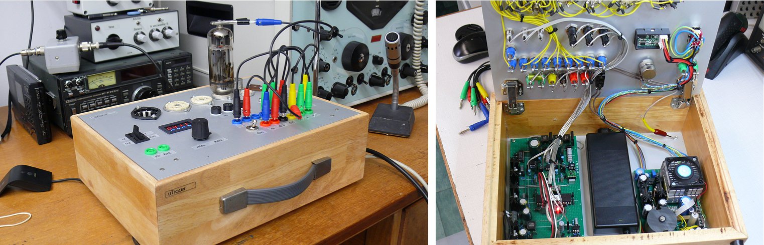
Dag Ronald,
Het is maar goed dat ik twee processors besteld had want hij is toch echt overleden. De uTracer heb ik deels gebouwd met onderdelen uit de junkbox. Voor de SPA07n60 heb ik de IRFP450 gebruikt aanvankelijk zonder buffer dus met de gate direct aan de processor. Waarschijnlijk is dat de oorzaak ( veel meer terugwerking dan de SPA07n60 ) voor het overlijden van de processor. Over de werking ben ik zeer tevreden alleen bij metingen met kleine stromen (kleiner dan 0,5 mA) heb ik wel wat last van een onrustig beeld.
Bijgaand een paar foto’s en het schema met wat veranderingen die ik heb aangebracht. De afgebeelde PL519 heeft al een heel TV leven achter de rug en haalt nog bijna de parameters van een nieuwe uit het Philips buizenboek. Wel bijzonder vind ik.
Met vriendelijke groet,
Ton van Megen
8th of February 2019 Christian Verdier uses his uTracer to design and build beautiful amplifiers!
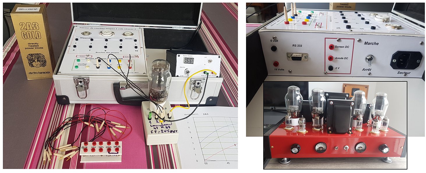
Hi Ronald,
I am writing to tell you that my first utracer bought a few years ago works very well.
I am attaching some photos of the utracer in a box with a 2A3 plugged.
I use it to measure triodes 2A3 and 300B with which I mount amplifiers BF.
I enclose a photo of a double push-pull 300B.
Best regards
Christian
3rd of February 2019 Gaetano Di Bella introduced a new way to connect different sockets to the uTracer. Great!
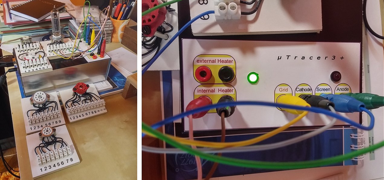
Dear Roland and Marie-José,
I finally completed the utracer. Fantastic! it works great and thanks to the simple and detailed instructions included it was easy and fun to mount the circuit.
Thanks again for the great work you do to feed the passion for the tube. I send to you some pictures of work.
Kind regards,
Gaetano Di Bella
31st of January 2019 Simon made a very practical rustic uTracer!
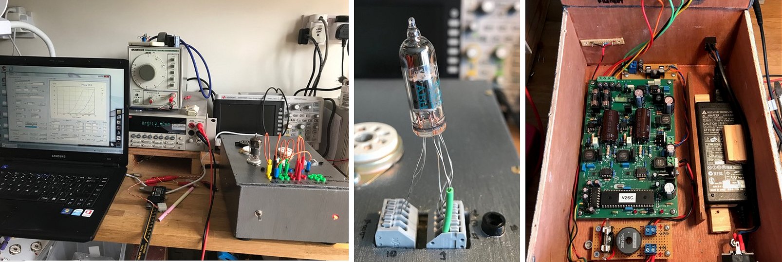
Hi Ronald,
OK, I admit I’m a little ashamed of my box. It doesn’t do your creation justice and compared to the industrial-smart uTracers on your website it would not even earn one star. In the interests of speed and saving money I made it from 5mm plywood, glued, and it didn’t look pretty. So I decided to paint it. The shop had some enamel paint suitable for models and children’s toys. I chose pewter, a colour vaguely close my scope and laptop. Well, if it had been a toy for my kids there would have been big tears on Christmas Day. Of course it works beautifully, which, I keep telling myself, is the important thing.
The grey things on the right are Wago 5-way push-in terminal blocks (Wago’s part no 250-405) for sub-miniature valves. They have little plastic push buttons to release the leads. The black socket is for pin 10 (the Russian sub-miniature 6N21B has 10 pins, which seems excessive for a double triode, but there you are). The Wagos work well, though I don’t suppose they were designed to have leads pushed in and pulled out all the time, so for how long, I couldn’t say.
This is a brilliant project. Although I’m still learning about all the things it can do, to have all. That information on a valve is immensely useful, so thank you again.
Simon
26th of January 2019 Mark turned his uTracer into an handsome instrument with beautiful rotary selection switches!
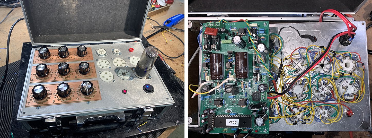
Ronald,
Thank you again. The kit was fantastic to build, and of exceptional quality.
Attached are pictures of my project so far, I have few more improvements I’m adding this weekend Bluetooth, and a new laser etched lettering, and have been working on an raspberry pi / wine solution for the lid.
I fit everything into a small case, with is very convenient.
Has 7,9,4,5,6,7 Octal, local sockets, and a plate/Grid Cap plug.
There are 9 - 12 pos rotary switches, 1 for each tube pin. This allows virtually any connection sequence.
The 12 positions allow for:
- Internal heater 1
- Internal heater 2
- Cathode
- Grid
- HV1 (Screen)
- HV2 (Anode)
- Continuous Hv1
- Continuous Hv2
- External Heater 1
- External Heater 2
I was getting oscillation, and/or erratic measurements , and tried your suggestions however after some experimentation a 0.01uF mylar cap across Grid and Cathode completely solved the problems.
If you look close you will see a failed attempt to use my CNC to route the face plate directly into the aluminum — opps more than my CNC could handle.
Thanks again!
Mark
22nd of January 2019 Boban from Canada sent me a few pictures of his nice uTracer with impressive “vintage style” anode and screen voltage meters!
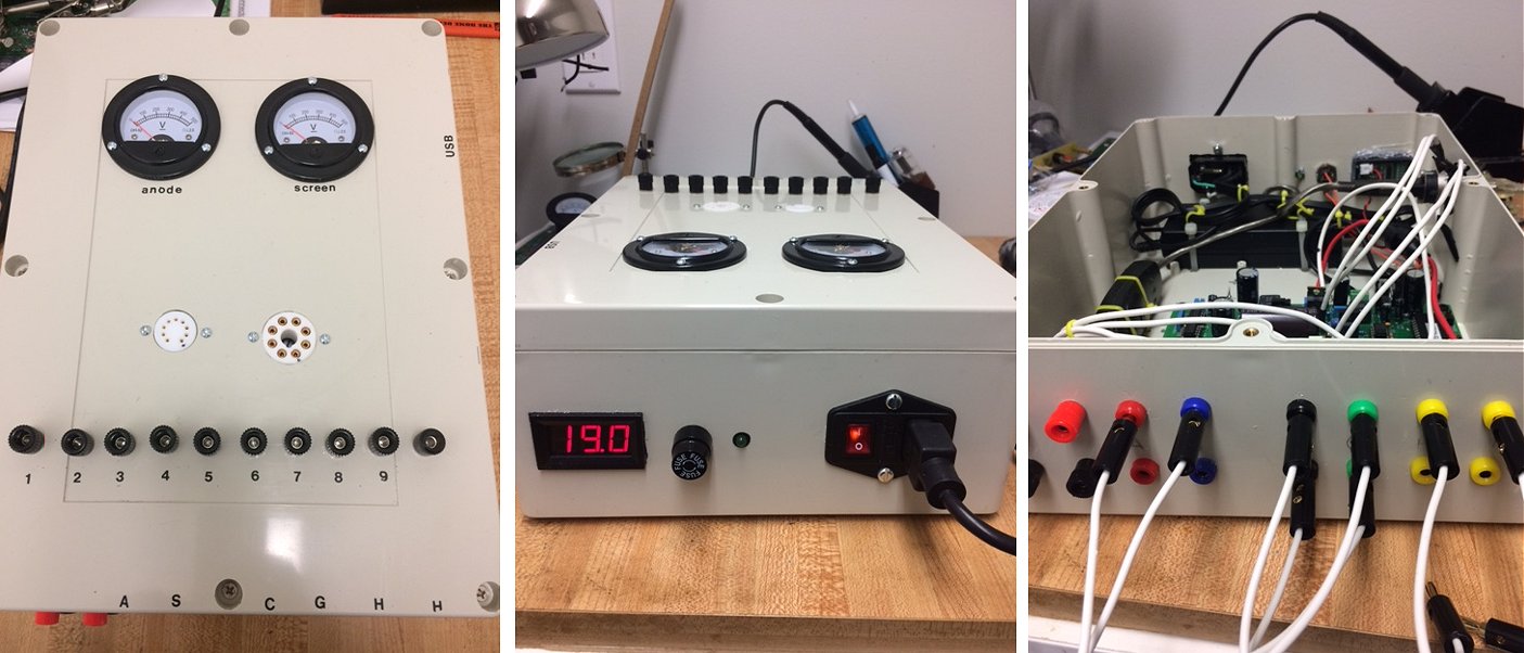
Hi Roland,
after many (and I mean many) months my uTracer is completed. Yes, there will be some modifications later; not on the kit, it is as complete as it can be but some additional things that I picked from the projects that are completed and posted on your web site ie. wireless communication, secondary heather, place led diodes on the front..etc. Thank you again for the wonderful instrument that will make my audio system better.. :-).
Please see my pictures below.
Regards
Boban
18th of January 2019 Lars Schädler made a beautiful “medieval style” uTracer! Great!
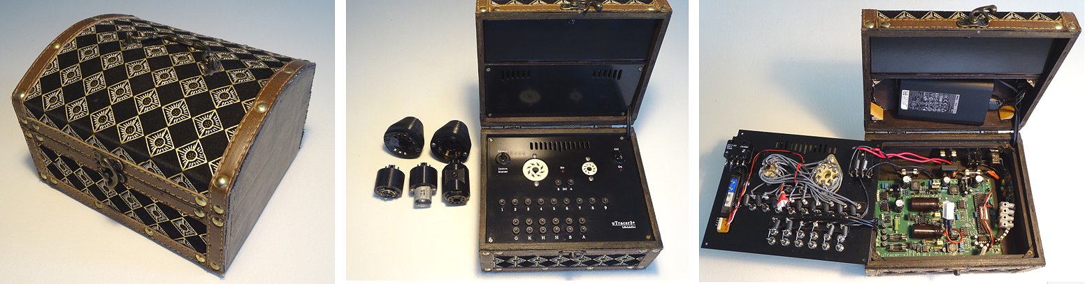
Hi Ronald and Marie-José
Better late than never!
Once again, thank you for sharing your work with others.
As promised, some pictures and a few words about my adaptation of the uTtracer.
I completed the circuit over a year ago, everything came together smoothly and worked at first run. It’s a great kit and very good documented.
In the beginning I experienced an annoying sound from L1 in the negative power supply, I potted the inductor whit epoxy (Ronal's suggestions) which made a huge difference, now its´s quieted. My wife donated me a box that became the starting point for the physical layout of this wonderful device. To keep it simple I only included an Octal and a Noval socket, also because these suits the tubes I usually work with. I have made some adapters for other tube types. Power supply is placed in the lid, and here are also a small storage room for patch cables, all external connections are located at the back. I hope space can be found to integrate the grid loupe circuit!
Many greetings
Lars Schädler
14th of January 2019 Peter Gillespie sent me a “glowing” testimonial!
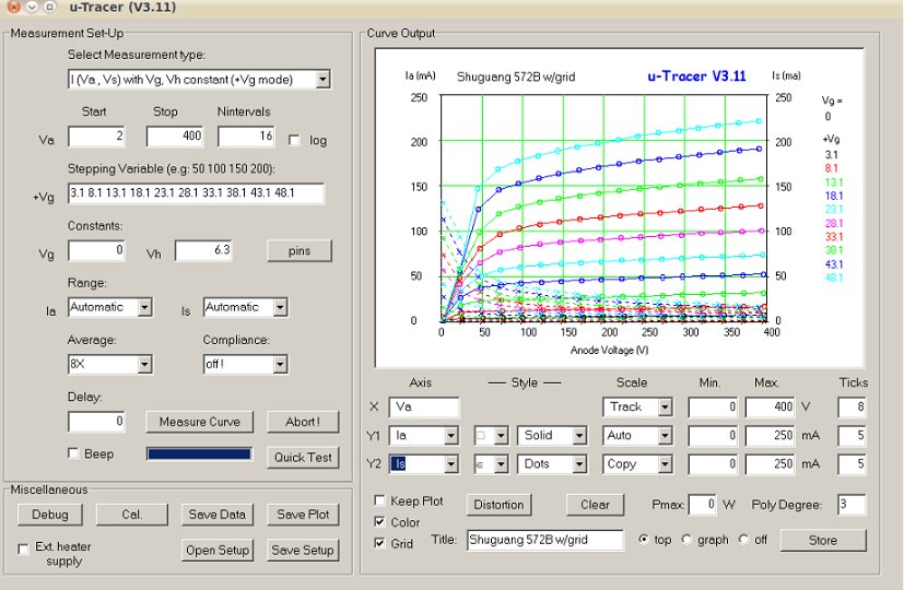
Hi Ronald and Marie-Jose
I finally got around to doing a testimonial, brief but to the point. I never did mount it in a box since the only testing I do is on the bench but I've included a picture of the plate curves for a 572B positive grind triode showing the grid current. The grid current is important to know with these tubes.
------------------------------
The utracer is an amazing, compact and inexpensive device not just for complete testing of a tube for for designing tube circuits!!!
-the construction manual is as good as any I've seen
-the components are all well labelled in plastic bags-a lot of time and care went into this kit!
-tubes are tested at realistic voltages and currents unlike many of the vintage testers that only use 150 or so volts.
-the quick test is very fast and gives the relevant parameters shown on a tube data sheet.
-it will plot the tube curves
-you can do a distortion analysis for the tube under test at your chosen operating conditions-great for designing!
-you can plot curves for positive grid tubes showing the anode and grid current (grid shown as Is)
A great thing for me is that the GUI works perfectly in Linux using WINE.
Ronalds support is superb!!! He's also continuing to come with improvments and new applications for it such as transistor curve tracing, re-forming capacitors and increasing current capability.
I've NEVER been happier with any device I've purchased!!!
----------------------------
Thank you all for making the uTracer available!
Peter
12th of January 2019 Ken Hutchinson reports his uTracer working and he is very pleased with it!
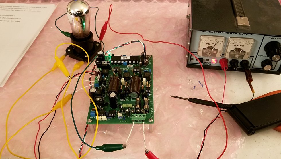
Hello Marie-José and Ronald,
I'm not sure that words alone can express the gratitude that many of us feel towards you both for designing, kitting, and shipping the uTracer to us at such a reasonable price. As I mentioned to you previously I became interested in getting a tube tester when an ongoing project to build a tube-based bass guitar amplifier expended in scope to include a long dormant desire to restore old radios, the 1920's era radios being my primary interest. Tube testers are curiously expensive in the USA. Even simple emissions testers in good operating condition can be more than half the price of a uTracer and they are frequently offered for prices well above the uTracer price, but I do not know if anyone buys them at those prices! The more desirable transconductance testers can sometimes be had for the price of an emissions tester but they often sell for several times the price of a uTracer. Getting either kind for a fraction of the price of a uTracer (which is all they are worth based on the difference in capabilities) is a matter of luck and frequently the willingness to take a chance on restoring a "basket case" that no one else wants.
I loved the concept of the uTracer as soon as I learned of it. I put off buying one because it seemed overkill in terms of price and capability for what I needed. But then I learned the reality of tube tester pricing and being an engineer myself there was always a part of me that knew that any capability that you can afford is never overkill. So, I ordered a kit from you right before the 2018 Holidays and virtually as soon as I did that I also managed to snag an emissions tester at a price near its worth because it was in need of some TLC (Tender Loving Care for those unfamiliar with idiomatic US English). I started work on the kit during the Holidays and finished it the Sunday evening before I had to return to work.
The kit is a joy, it takes me back to my boy- and young adult-hood when Heathkit and others sold a wide variety of marvelous things that you could build yourself. Everything is well packed and labeled, the quality of the components is high, and the construction manual is simply beyond compare! What a labor of love it is for you to provide it to us at this price.
I only had three issues while building it. A solder short that I missed burned out the power on LED when I went to test that circuit. In the photo below it has temporarily been replaced with a tiny green incandescent lamp which I will soon replace with an LED. The second issue was that you underestimated how many of those tiny ceramic beads I would drop, and lose, on the floor before I wised up and came up with a better way to handle them! I was careful to correctly space above the PCB the two resistors that had to make do with only three beads. And then Sunday evening when I went to do the HV switch testing and final calibration I had no HV output, or at least no current reported in either of the 10k load resistors.
I did some troubleshooting on Sunday which included verifying that load resistors tacked on ahead of the HV switches would produce the correct current graph display. But I had to put it aside in un-working condition until last night. While I was at work yesterday I decided I should dig out my USB oscilloscope and check the control signals with the HV set to a range low enough that the scope could deal with. It did not take long last night to see that while the screen supply pulses were present on the uP output, the anode supply pulses were not. That led eventually to finding a solder short that connected pin 20 of the uP to the 5V supply bus. Luckily modern uP chips are usually designed to tolerate this kind of abuse and when I removed that solder short I was suddenly back in business! I include a couple of quick photos below that show my crude test setup and a screen shot of the results for an ancient 01A radio tube that I selected for my first attempt at using the uTracer.
I could probably get along for a while with loose tube sockets and clip leads as you see in the photo but I plan to quickly integrate the uTracer with either the Heathkit TC-2 emissions tester that I have restored to operating condition or perhaps put it inside another old tube tester hulk with major, irreplaceable pieces missing that you can occasionally get for very little money. Still trying to decide on which way to go and I will send you more photos when I make a decision and complete that part of the project. But in the meantime thank you, thank you, thank you for making this wonderful kit available to the vacuum tube collector and user community!!
Ken
9th of January 2019 Patrik Chrvala from Slovakia sent me a few pictures of his beautiful retro looking uTracer!
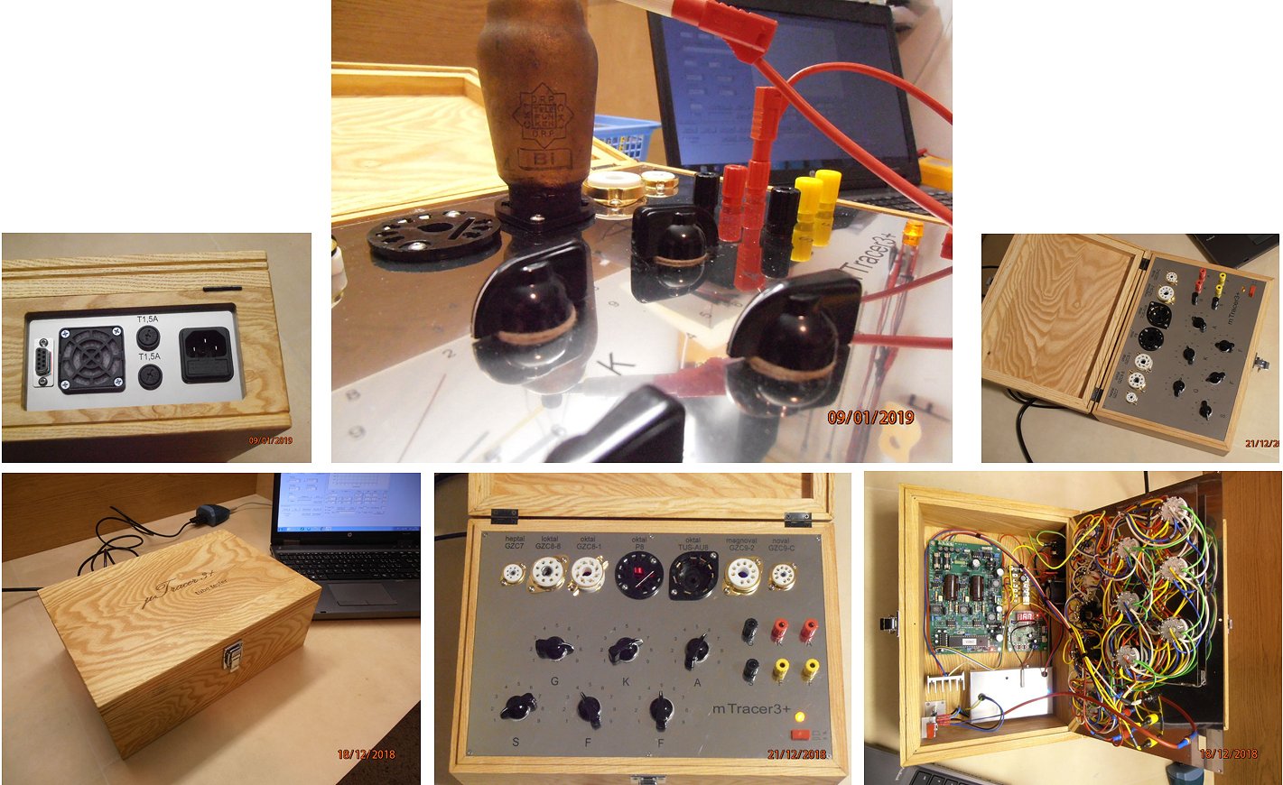
Hi Ronald and Marie-José.
While it took me a while to finish the tube tester, l can now only confirm what is written here by everyone. Perfect instructions with photos, descriptions of activities, PCB with components and of course the overall result. I will now have a lot of work sorting out the older tubes that l own as l don’t know what condition they are in. I am very satisfied with the tester and l would certainly recommend it to others.
Thanks!
Best regards
Patrik Chrvala, Slovakia
6th of January 2019 Doug Barker sent me a few pictures of his very nice and compact uTracer!
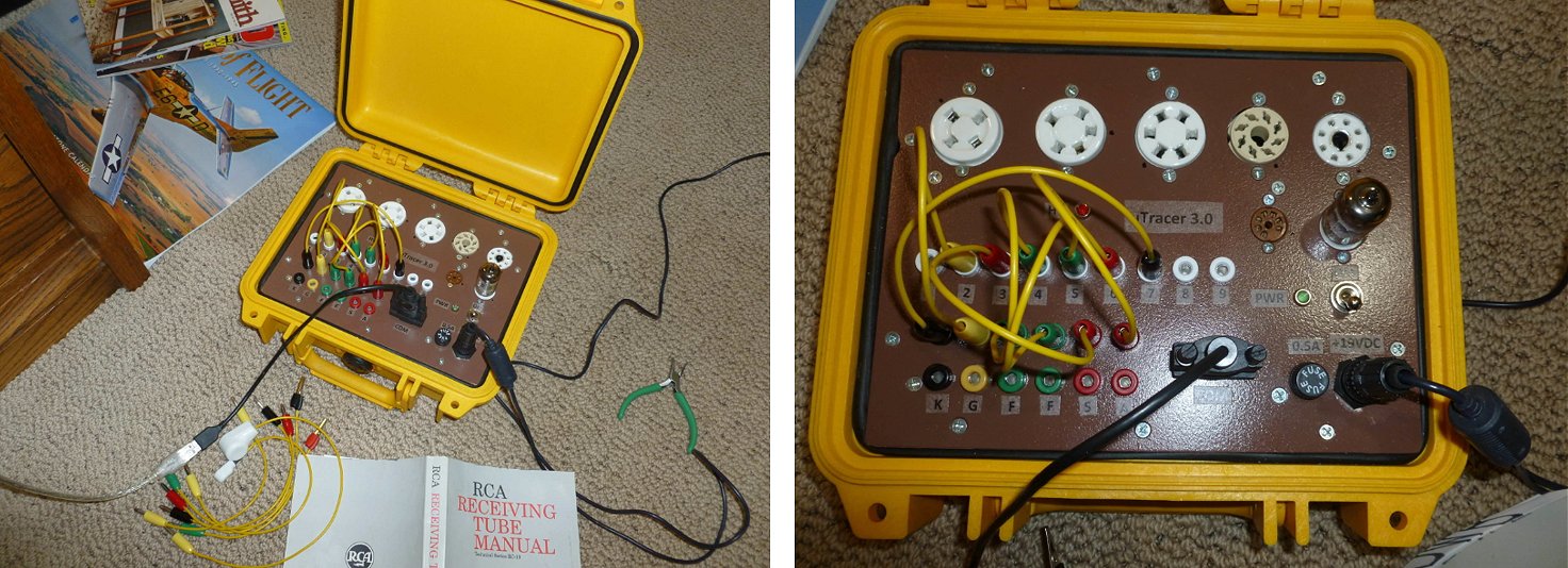
Hi,
I thought I’d send you a couple pictures of my utracer that I just finished. I had been thinking about building something for experimenting with tubes and do some design work with them. I had acquired some old tube testers that I was going to cannibalize for that purpose sometime after I retire, but then I found your website. That’s a really innovative design. Thanks!
Doug
2nd of January 2019 Michael Smith was the first to send me a testimonial this year and it had as subject “Satisfied Customer!”
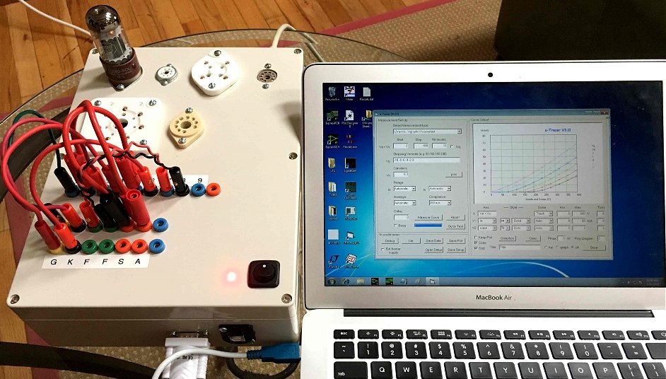
I assembled the uTracer 3 according to the excellent instructions, and it worked perfectly on the first try.
Thank you for an extremely well-thought out product.
Attached is a picture of the uTracer in action, testing a 6SN7 with a MacBook running Windows 7.
Thanks,
Michael Smith
Weston, CT, USA
26th of December 2018 Ingemar Moran from Sweden used Christmas to finish his nice and straightforward uTracer!
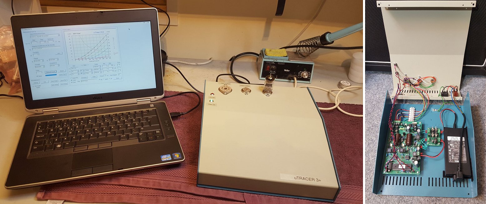
Hi Ronald!
I finally finished my uTracer this Christmas. Thanks to your excellent kit and instructions everything worked fine. As I have limited skills in mechanics I think I spent most working hours selecting a chassis and then drilling and screwing and installing uTracer into the box. I also have been very impressed by the uTracers that other users have built. Most of them with very nice and useful features. Because I am mainly working with audio equipment and I am using the most common power and pre amplifier tubes I went for a simple build with no switchboard. I think there is plenty of room in the chassis if I want to expand for this possibility in the future. I have included some images of my build and my testing of a Russian 6N1P.
Best regards and a Happy New Year
Ingemar Moran - Sweden
17th of December 2018 John Schenk sent me a few pictures of the beautifull vintage uTracer he made from the present he got from his son Steve! (in Dutch)
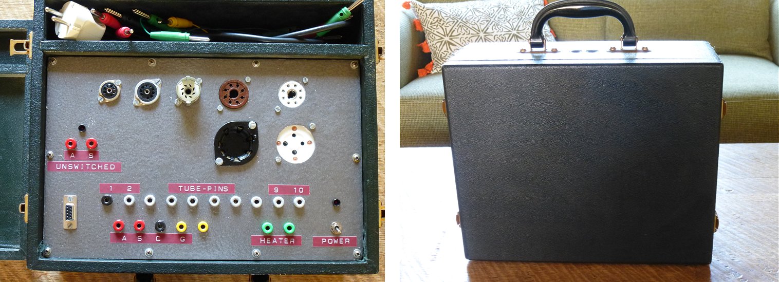
Beste Ronald,
Mijn naam is John Schenk en ik ben de vader van Steve,die enige tijd geleden de mu-tracer voor mij besteld heeft.
Vanaf het bouwen,instellen en testen heeft het project mij veel plezier bezorgd.Je heb er echt iets moois van gemaakt.
Het apparaat functioneert naar wens en voor mij is hij goed zoals hij is.
Het enigste wat ik mis is een hogere negatieve rooster spanning,zodat ik 300B buizen kan testen.
Nu doe ik dat door de anode spanning en dus de NRS ook laag te nemen.Het werkt.
Is het ook mogelijk om voor de NRS een externe voorziening te gebruiken?Die heb ik n.l.wel en is instelbaar van 0 tot -100 V.
Mijn CT 160 Van AVO gaat ook maar tot 40V NRS.
Aldus nogmaals mijn dank voor dit bijzondere apparaat.
Verder wens ik Marie-José en jou gezellige feestdagen,een vredige kerst en een gezond en creatief nieuw jaar.
Met vriendelijke groet,
John Schenk.
11th of December 2018 Martijn Scalé sent me a few pictures and an enthusiastic testimonial of his nice and compact uTracer!
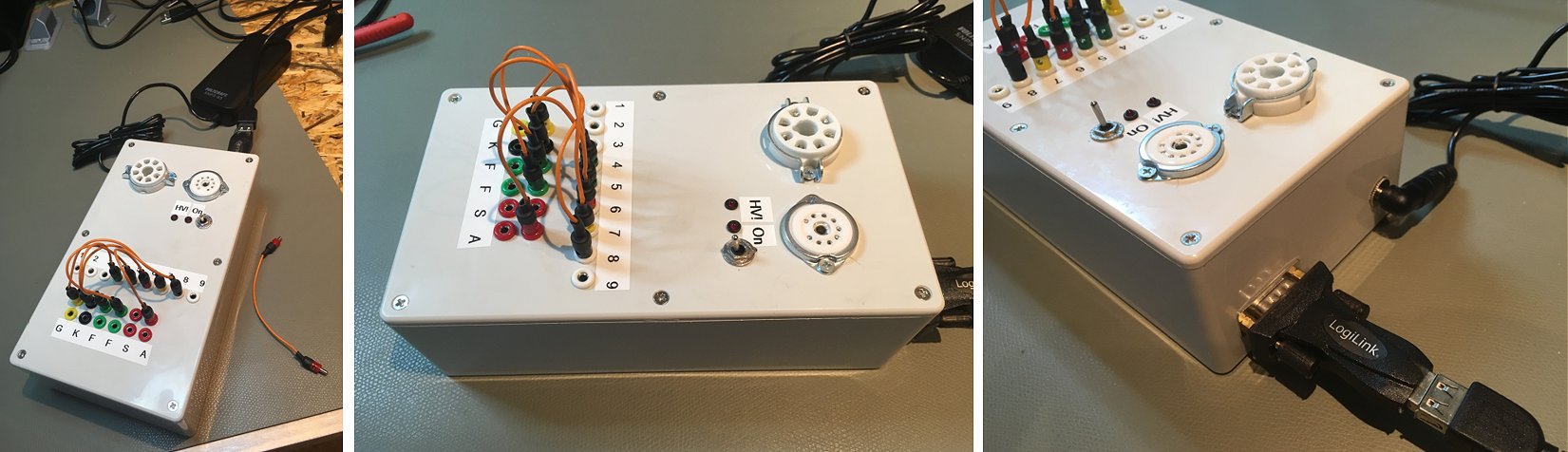
After working with tube amplifiers for some time, I found my shack filling up with tubes, some of them deteriorated, some broken. Time to find a test-device and sort what is what! The uTracer 3+ is an excellent choice, with a huge fan base and widely used all over the world, so the advertisements say. Well, let me tell you, it is an excellent choice!
Already the unpacking after receiving the uTracer kit is a great joy, you can see that a lot of thought and love has been put in putting the kits together. Most of the components sorted and labelled, semiconductors neatly stuck in foam, a great looking PCB with two SMD parts already on it. And extended documentation, which takes you step-by-step through assembling and testing the sections that make the uTracer.
The kit comes without a box, making you think of how you are going to use the uTracer and what type of box fits your needs. There are many examples out there to get you going, so that should not stop you. The development of the uTracer does not stop, thanks to the effort of Ronald and the community enhancements are designed, as well as new ways of using the uTracer thought of.
All in all, a great kit and a great (building) experience. I would give it 9 out of 10 points.”
10th of December 2018 Tjorbjörn Tjärnhage from Sweden has a first, a vertically mounted uTracer! Together with some friends they also organized a Swedish uTracer test!
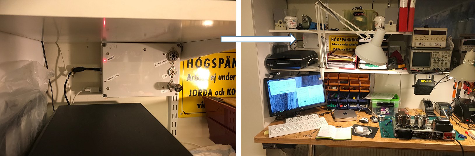
Hello Ronald,
So, finally I managed to take a couple of pictures of my u-tracer build and installation.
I mainly do simple service of guitar amplifiers and did a little shortcut in the socket layout of my build. one EL34/6X6 oktal socket and one for EL84 and one for ECC8x style tubes. That pretty much covers virtually all tubes I will encounter. No internal patching possibility therefore. On the few occasion that I need to test another type of tube, I simply solder a socket adapter ”bridge” from one of the present sockets.
I have a small workshop, and I use an older Small Form Factor Dell-computer (nice though with many USB and also still had a RS232-interface) running W10. I attached the plastic box with the u-Tracer on the wall between two shelves above my working table. Works good enough for me.
To conclude the u-Tracer is really a helpful tool for me and will quickly tell me the condition of the tubes in the amplifiers that I work with and also extremely helpful when selecting new power tubes (matching) or selecting a suitable preamp tube specifically for a certain role (phase inverter for example).
The u-Tracer was easy to assemble as the instructions were excellent and clear.
Last year, I managed to get in contact with some other fellow amp-repairers in Sweden that were using u-Tracer and we sent a couple of tubes around to each other and the test results were just within a few % so we can conclude that the design and calibration routines is really working.
So finally thank you for your excellent work on the Tracer and to make it available at an affordable cost!
Greetings from northern Sweden.
Torbjörn Tjärnhage
9th of December 2018 Philippe reports his uTracer working! I cannot wait for the boxed version!
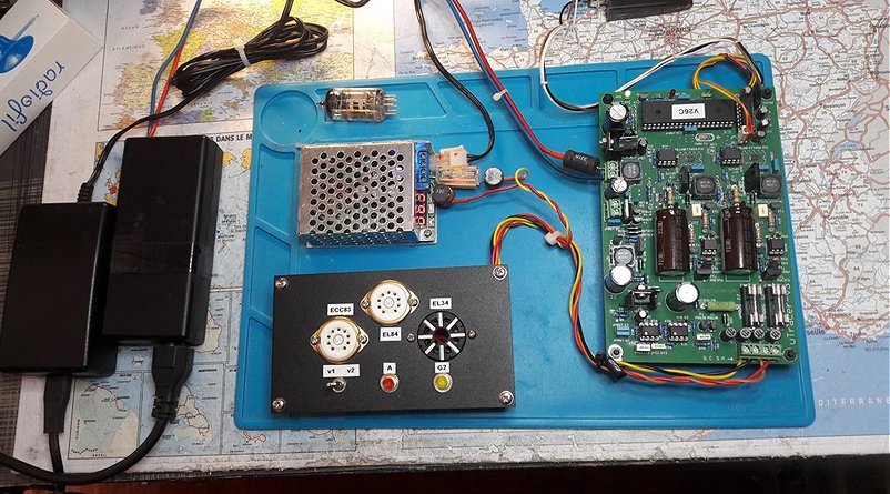
Hello Ronald,
I have your pcb being edited ... :-)
it works well but I must now mount a nice box.:-P
25th of November 2018 Yukiya’s uTracer in Japan came to life!
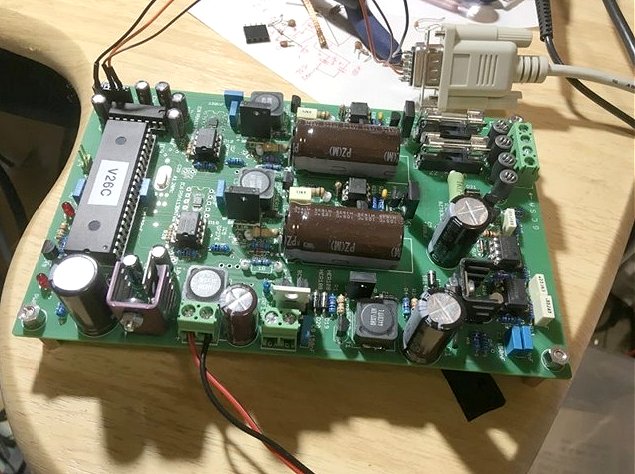
Hello Ronald and Marie-José
I finished assembling and calibration.
It was easy because of your detail manual.
I will create socket box.
Thanks!
Yukiya
16th of November 2018 Ari Huju from Finland made a beautiful uTracer that opens like a book!
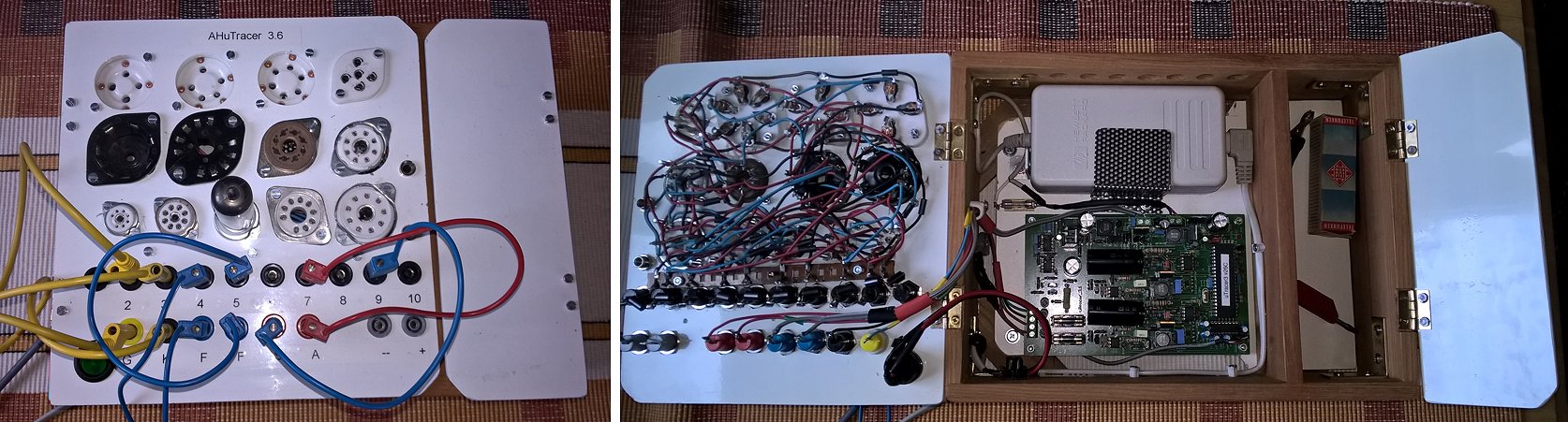
Hello Ronald and friends!
It is very nice to write You for a very long time. And thanks for the very well working uTracer. My tracer is old, but I haven’t yet sent You even pictures of the ready uTracer working. So here they come, hopefully You mail does not fill. Settings are EL86. You can see from pictures, that I have not made the other raw of banana plugs down. When it comes two or more connections to same plug, I just put them together to same banana point. It has worked so far and I have not seen any oscillation or so.
The 400V parts are still waiting in the box some good day, job is small, but beginning is big.
Nice weekend and many Greetings from here Finland,
Sincerely Yours
Ari (Huju)
15th of November 2018 I can only say Whow to Pierre Molitor’s uTracer! Please visit also the description on his website (in French).
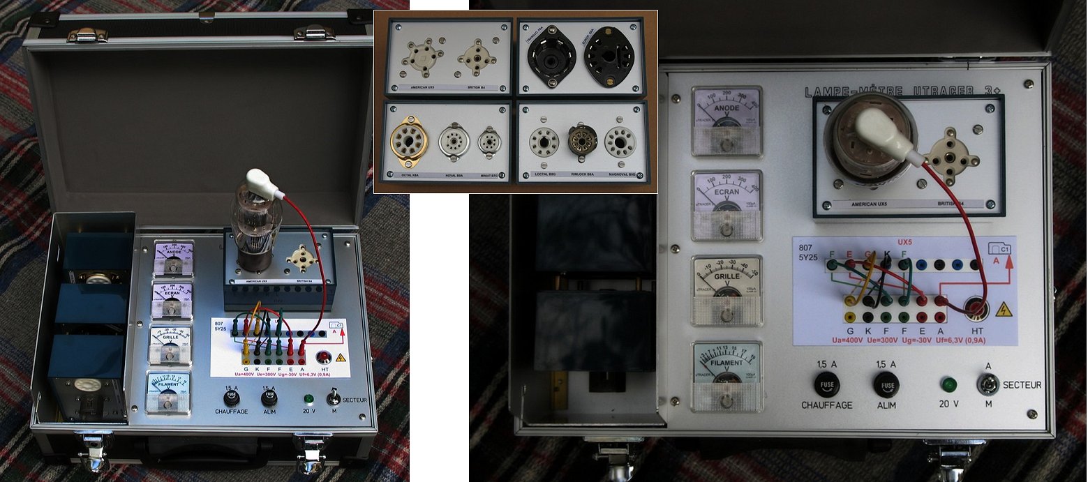
Dear Marie-José and Ronald,
First of all I would like to thank you for having imagined and put at our disposal this kit to realize a tube tester. It worked perfectly after each stage of construction, the assembly instructions are very well done and if we follow it step by step, the result is guaranteed.
The bulk of the work is to make this circuit convenient to use. I chose to put it in a suitcase that is easily found on the Internet and have a simple and scalable system for the tube supports.
I have dedicated a page on my website (in French!) with a detailed description and some pictures: http://www.rotilom.com/F6IDT
Thank you again for this device that is much more efficient than conventional testers that are no longer manufactured.
Kind regards,
Pierre Molitor (F6IDT- France)
11th of November 2018 Aleks from Russia sent a few pictures of his uTracer, I wish I could make something as beautiful as that!
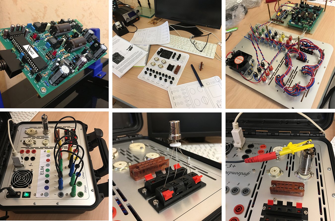
Dear Marie-Jose and Ronald,
I purchased Complete uTracer 3+kit in 2017.
Finally I finished constructing my device.
Your manual is great, it is very easy to construct uTracer with help of your manual and advices.
It took me so long to finish cause unfortunately I have little time for my hobby.
My uTracer is ready for work now.
You can find some photos of it attached to this letter.
To make connections easier for me I used cards with color-codes.
You can see examples on my photos.
Thank you for your very well-done job
Cincerely yours, Aleks from Russia, Moscow
4th of Noveber 2018 Eric van der Velde finished his very nice and compact uTracer!
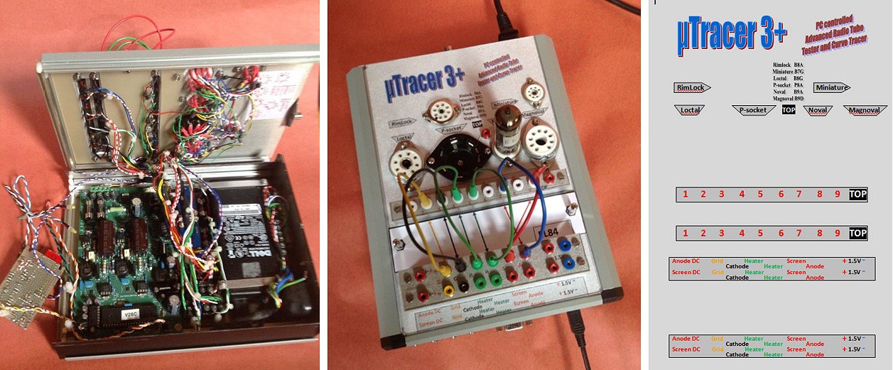
Dear Marie-Jose and Ronald,
My first tube project was building a phone preamp with 3 times ECC83. Next will be a complete tube audio amplifier using no semiconductors at all. But how to select the best tubes from the junk box? After some experiments with a Heathkit TC2 and the US tube tester I177B I got more interested in testing radio tubes. For me it is old school technology. I was grown up with semiconductors and processors. I've a nice collection of tubes but selecting or matching with a go/ no-go tester is not really what I was looking for. Via the web I found the uTracer website. Really beautiful!! A great design, so I ordered a kit. Many thanks to Ronald for the technical work and Marie-Jose for the logistic support. Delivery was very fast and the kit was very well packed.
In the junk box I've found a nice case. But it is not very big so a real challenge to have all components fitted. Especially the height was a challenge. I had to do some mechanical work. Because additional to the uTracer printed circuit board there is an old laptop power supply, two step down converters (one for the 1.5Vdc battery voltage, the other one supplying 5Vdc), the small home brewed USB/RS232/BT interface and not to forget all the wiring. The 5V is used for the small home brewed interface. Now it is very easy to connect a PC to the uTracer, it can be RS232, USB or Bluetooth without any switching. I used some old TTL ic's to make the combiner for the interfacing. Just connect and select the right COM port in the software. On the rear there is a male 9 pin outbreak connector to connect small cases with less common used tibe sockets. On the tester itself I selected the Rimlock (B8A), Loctal (B8G), P-socket (P8A), Noval (B9A), Miniature (B7G) and Magnoval (B9D) socket. I use small plastified cards for the connection diagram. Quite simple. The construction manual is very well documented. The uTracer worked at once. Started testing with EL84 tubes: one tube had only 8mA Ia with 300Va, 250Vs, -0Vg. Other EL84 tubes had an Ia of more than 100mA. So it is very interesting to play with this beautiful tester. Most ECC tubes in my junk box have identical curves for both triodes, but I found also some with (great) difference. Many thanks for this great tool.
Kind regards, Eric van der Velde (pa2reh) - Netherlands.
27th of October 2018 Helmut Heller’s uTracer has a very “rustic feel,” and he surprized me a beautiful and extensive testimonial!
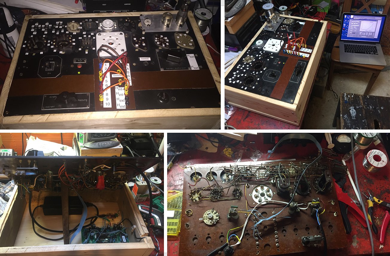
Hello Ronald,
Just like you, I LOVE tubes! Their soft glow has always fascinated me. When I was 5 or 6 years old, I admired the magic eyes on old broadcast band (MW) radios, with the soft red glow in the middle. Looking at the back of the radio was much more interesting than the front: one could see all the tubes glowing and appreciate the wonder of producing music from invisible radio waves, just by guiding electrons through a vacuum!
A few years later I experimented with a KOSMOS Radiomann and the EF98! So much fun! Could this tube do more than what Heinz Richter told me in the manual? I experimented with different voltages, but it was "poking in the dark”, as more was not always better.
I grew up, semiconductors took over, I became a physicist, work was exciting and took all my time. Then my wonderful family with three sons became the focus. Luckily, all three are more or less interested in the natural world, physics, electronics — just not in tubes :-| So tubes stay a solitary hobby for me.
I had always wanted a tube tester, e.g., to see what the EF98 can do outside the normal operating conditions. I looked at old commercial tube testers (now available on eBay) and various kits. Your µTracer stood out: not too complicated, yet much more powerful than simple go/nogo commercial testers, and at an affordable price point. I also liked your impulse measurement technology, as it allows to measure outside the safe operating range of tubes without danger to the precious tube. A few years ago I got a kit for Christmas from my wife and oldest son. That was so wonderful, what a great gift!! I searched on eBay and luckily found the front of an old self-built tube tester with a lot of sockets in it. The transformer and all electronic was missing, but this was just right for me and the µTracer :-) However, work was too demanding and your kit lay dormant for over two years.
Recently, I managed to set some time aside for my tube hobby; I assembled your kit, which worked fine on the first try. I then had to add some “modern” tube sockets (pico 7, Loctal, etc.), a 2mm-socket switchboard, and some LEDs to my front panel. I re-used the old neon indicator lamps for “line voltage” and a gas test (employing the screen grid voltage in continuous mode, tapped directly at the 450V capacitor via a 300k resistor). I am also re-using the old on/off switch, which gives it this 1950’s vintage touch. I replaced the HV LED with an orange self-blinking LED to be more obnoxious when high tension is present. Impossible to overlook now ??. Then I had to build an enclosure. I am really not the world’s best carpenter, and this shows. Oh well, it is a test gear, not living room furniture. Power supply, µTracer, and the USB converter (I removed the MAX232 and connected the FTDI board directly) all find space in the void unter the sockets.
Ronald, I have to tell you, you did a really excellent job with the µTracer! It is so much fun to work with it!! I can now trace the EF98 in triode mode, at various anode voltages outside the recommended range, find out how it behaves with g3 connected to cathode while g2 is connected to the anode, etc. Or testing an old 12V car rear light bulb with one burnt-out filament as a diode, varying the “heating” voltage and recording the emission. Wonderful!!
I am enclosing a few pictures and if you want to put this on your testimonial page you have my permission! (I am using a hammer to prop open the lid while taking the inside pictures)
All the best to you
bye
Helmut
25th of October 2018 Nicolas Buligan’s uTracer is in the popular “Manning style.” He has some usefull tips to run the GUI under Wine which I shall include in the FAQ page.
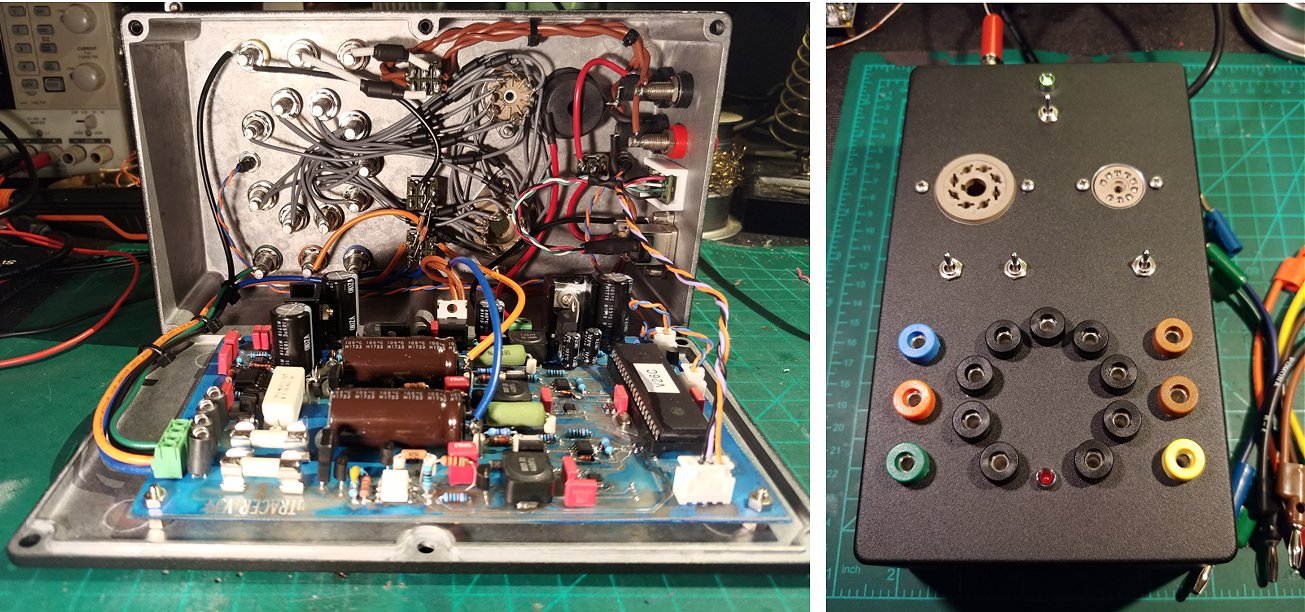
Hi Ronald,
I finally sorted out the issues I was having with the negative supply and now have the uTracer up and running. I decided to power the FTDI module from the internal 5V supply and have not had a single issue with the PIC latching up. Although the resistor work around did sort of make the issue less scarce, it didn't fully eliminate it and I burned through another set of OPA227s!
I opted for a vertical "Manning" type layout and I'm quite happy with the result. It's a great compact design and it totally suits my needs. Oh, and please ignore the ugliest solder mask you've ever seen! I had the transparency done up at a different print shop than normal and unfortunately the toner wasn't dense enough. After drilling all those holes I decided I was cool with a mottled blue PCB.
I've been running the GUI in Arch Linux through Wine but it takes a bit of setting up. I've included some directions.
Thank you for creating this device! After a few months, I'm quite excited to finally spend some time with it!
Nicolas Buligan
22nd of Oktober 2018 Steven Westby (WB7VHR) is very pleased with his uTracer!
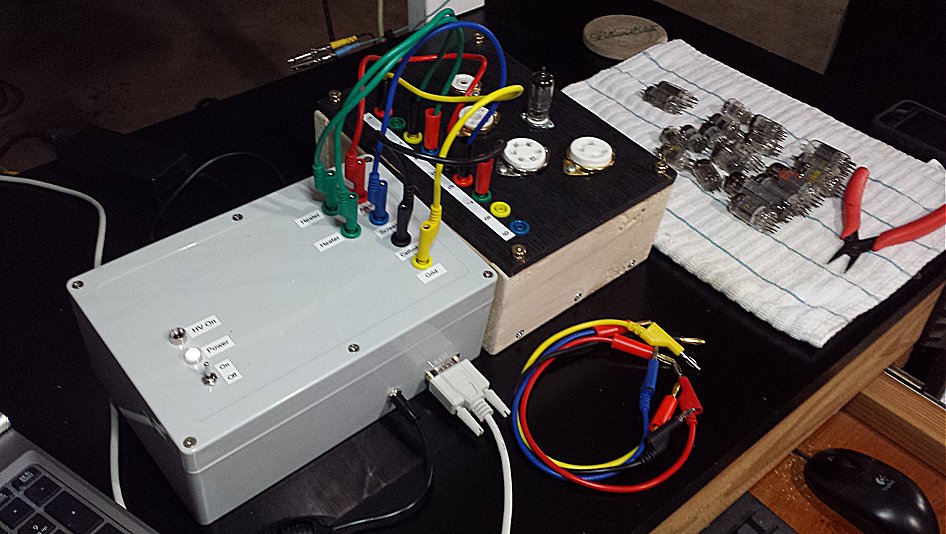
Ronald and Marie-José,
It took a while but I have finally finished the µtracer 3+ tube tester kit you sold me in June this year. It took a while to get started on the build as there were a few other projects in line ahead of it, but now it is complete. It went together very easily, and frankly was a lot of fun to build. I almost wish I had another one to assemble considering how enjoyable it was.
I was very pleased with the quality of the PCB and the active and passive components you selected for the kit. Overall, it is an outstanding product.
I put together a tube socket box with basic four through nine pin sockets. I may add a few other socket types in the future. I used banana jacks and cables similar to what was shown in the construction manual. I had a notion of putting together a computer driven relay matrix to switch the sockets, but decided against it once the cost in both time and money became apparent. A project for another day, perhaps.
I ran my first set of curves tonight on an old RCA 6AU6A I had laying around. The curves agreed very closely with the RCA data sheet for the 6AU6A, confirming that the tracer works and the tube is still functional. That tube has to be at least fifty years old. That it still works was a big surprise as it has travelled everywhere in my electronics junk box over the years through several homes I have owned, and has not received the best treatment.
I do have one question, that being are there any plans to make the user manual available as a pdf file at some point? It would be handy to print out and place in a binder.
Thank you again for putting together such a fine kit.
Best Regards,
Steven Westby
Amateur Radio Operator WB7VHR
FCC Commercial Radiotelephone License Holder
30th of September 2018 Luigino turned his uTracer into a beautiful instrument with rotary switches, my favourite!
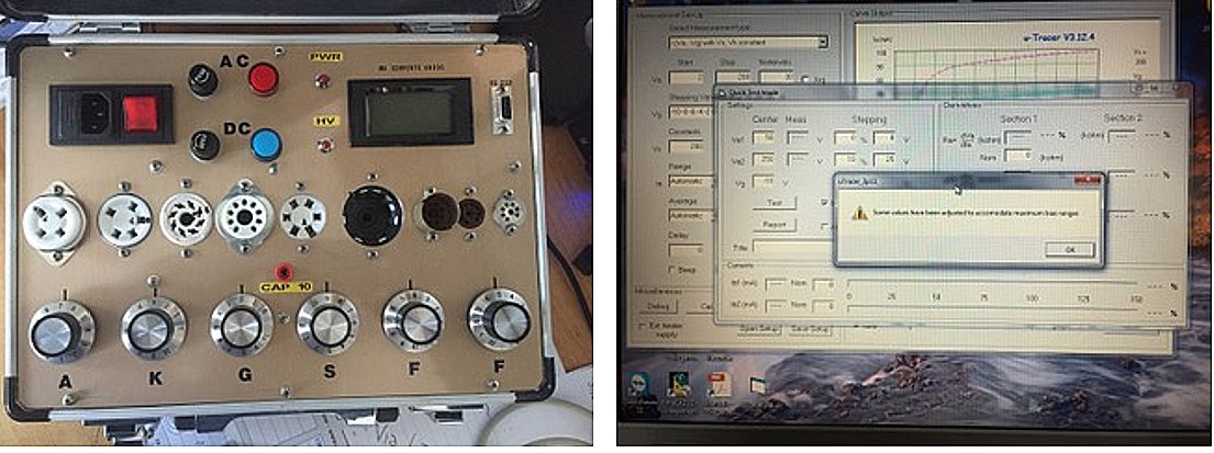
Hi, I'm Luigino Giuliani,
First of all, I wanted to thank you for the repair of the u-tracer that now works perfectly, now I wanted to ask you some advice. I kindly wanted to know the setup parameters for the test of a double triode type 12AX7 or similar, moreover in the fast test of the EL84, by entering the parameters as in your manuals, the anode voltage goes up to 50Volt also exits a warning as photos attached, I state that I popped up for tests at 400Volt. I enclose a photo of my prototype for an evaluation.
Sincerely
Luigino Giuliani
30th of September 2018 Peter Bulanyi is obviously a Radio “amateur” and for RF enthusiasts there is only one type of case!
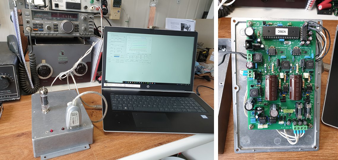
Hi Ronald,
I hope this email finds you well.
I successfully built the uTracer, and it works great. Many thanks to you and Marie-José for making it available and you have a uTracer working in Coffs Harbour, NSW, Australia now ??.
I learned a great deal while building it, and now I look forward to expanding my understanding of the operation of valves. Attached are some pics.
Kind Regards,
Peter
17th of September 2018 Jaime Mayoral’s uTracer is up and running!
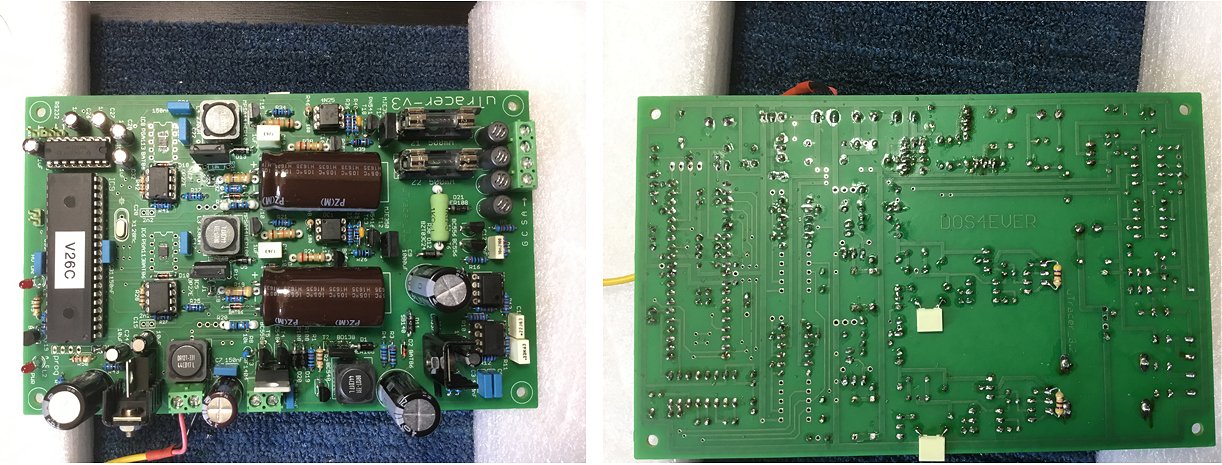
Hello Ronald,
greetings from Miami! I hope that you had a nice and deserved holidays!
I am happy to report that yesterday I finalized the basic assembly of the components on the pub for the utracer. Measured values obtained during construction were similar to those included in the manual. Good job with the manual! it is easy to follow with plenty of tips! thank you for such a great job. I will temporarily connect a tube socket today and run my first test. I also bought a plastic case water proof that I am planning on using for the final assembly of the utracer (this will take me longer time).
Calibrations were also easy to follow and to perform. I did a small mistake that was detected on time and everything went smooth after that. The only issue I am having is with the calibration of the grid bias circuit. It was relatively easy to calibrate it for the -40, -4 and -1.5 Volts. The values are spot on after calibration (i.e -40.02, -4.02, -1.51). However, when using the Vgrid (sat) to calibrate the low values I had to go all the way to the lower end of the slider (left) to get close to the desired values but I can not get to them. This values are the closest ones I can get (with the slider all the way to the left, see screenshot attached).
For -1.0, the value measured with the digital voltmeter -0.972
For -0.5, the value measured with the digital voltmeter -0.476
For -0.2, the value measured with the digital voltmeter -0.180
Do you have any tips to try to get closer to the target values? It is remarkable that my slider is all the way to the left. I saw on line the calibration screen of other builders and their final setting for Vgrid (sat) is closer to the middle of the range, meaning they have a better control of this parameter over and below the desired value (this is not my case).
I will keep you posted with any future progress. Receive a big thank you for putting all this together for us!
Kind regards,
Jaime Mayoral
11th of September 2018 Joe Rossi’s utracer has seen the light and he already turned it into a beautiful instrument, running it on a Raspberry Pi, a first I think!
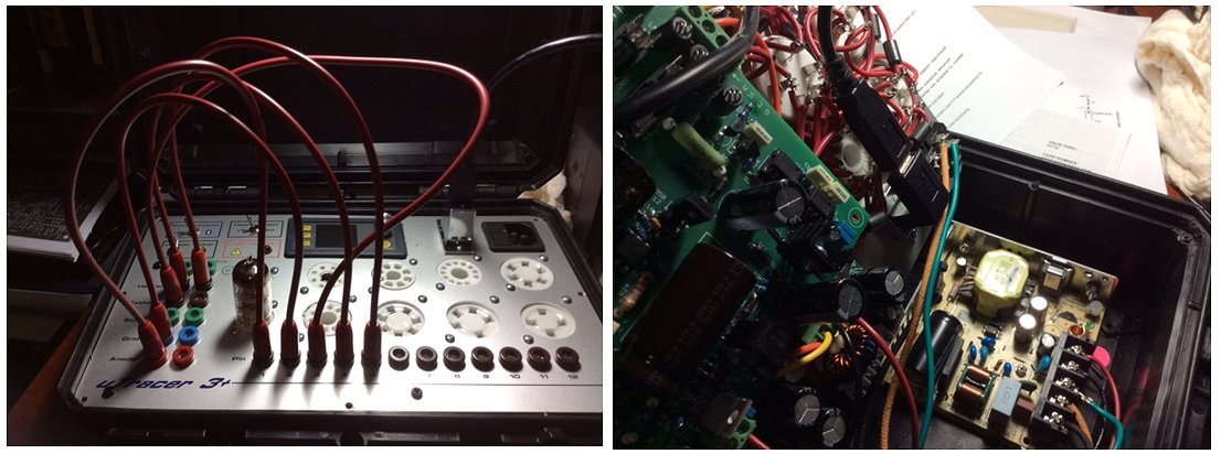
Good Evening Ronald and Maria Jose!
The uTracer is alive and working just fine. The attached photos show a 6BQ7A under test. A bit of an odd tube, but it was the nearest at hand. I am running it on a Raspberry Pi3+ using Ubuntu 18.04. Here are some additional photos of the test and enclosure. The only thing I have a question on is why the HV light stays on after shutdown. It turns off after I disconnect the USB cable. I want to thank you so much for the great enjoyment this has brought!
God bless you both,
Joe
4th of September 2018 Jeff Brooks’s uTracer came alive and he sent me a very nice testimonial
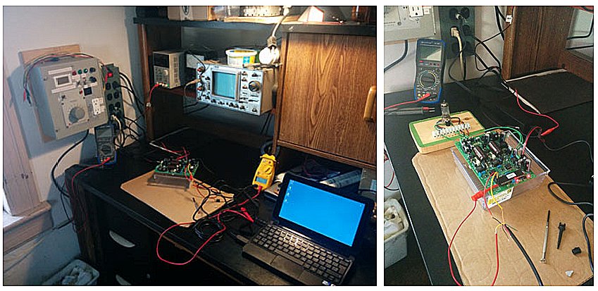
Hello Marie-José & Ronald,
I just want to advise you that I dedicated this last weekend to getting the uTracer built, tested / calibrated and trying it out. I am thrilled to say that I was able to put this together without any errors along the way - pretty good for a guy who usually just works on point to point. I attribute this to having developed pretty good soldering skills over the years and my Weller WS-51 solder station but way more so to the efforts of Ronald Dekker in providing a damn near bulletproof assembly manual and continually seeming to make things easier for the assembler - I noted several kit items that were obviously improvements on the original build manual, example, the now looped inductors.
I set up a crude valve base to do some tests on real tubes as the final product for this thing is a ways off - mainly because my parts order out of China seems to have disappeared in the mail. The Chinese also shipped me the wrong FDTI USB cable and are sending the proper one so I apologize for the butchered appearance of the USB connection. I have included some photos of my testing and my lab as it is. I am an old guy who understands a fair bit about electrical theory but I am super appreciative again to Ronald for doing all of this legwork with the GUI to make all of these calculations automatic and believable. I got really good results from a new JJ 12AX7 compared to spec and have tested two 12AU7s, one being British and showing much more life than the other RCA - both tubes still very usable according to uTracer. I also looked at two CV1991s and one 6SQ7GT (they are identical spec) and uTracer clearly showed a variance in these three tubes. The 6SQ7GT actually lines up with one of the CV1991s closer than the two CV1991s. This thing will be awesome for matching.
I am just beginning to understand the GUI and I think it is a work of art Ronald. It is not perfect but for free I am not going to complain. I will say again that it sure is awesome to have someone like you in this world who comes up with something like this, offers it to the world for cost (in my opinion and worth every thin dime), continually improves upon it, will support it (although I did not need to ask you anything because you have done an excellent job of documenting all of it including FAQ and Notebook on your website) and simply wants to share it. We need many more like you good Sir.
Once I have the final product completed I will send you some photos. I have a nice, like new, instrument mechanics tool case here and intend on it having a Weidmuller 24VDC power supply internal to split to the uTracer and also to provide a higher amp filament supply. It will be a bit of a challenge to get all of it in place but the hope is that I can test 6 different tube bases (guitar focused) and have the mini HP netbook fit in a compartment so the thing is totally portable. I have ordered push button selectors for the uTracer / tube interface but am backing it up with point to point test points as well. It should be practical, functional and pretty when it is done - that is the vision, maybe not the end reality!
Thank Man, you rule for certain.
Jeff Brooks
11th of September 2018 Stephen Kraig made a posts concerning the uTracer on his website, he also made a podcast! Check it out!
Hi Ronald,
I just wanted to give you heads up that the first two posts about my uTracer upgrade are live on my website analogeng.com. In one of the last emails I sent I said that I would be using circuitchat.com but I found that analogeng.com was available and I liked that better. The first post introduces my upgraded uTracer and the second begins to break down the circuit design. I have a third in the works that discusses the code which I hope to have out soon.
The schematic and layout (in diptrace format) along with the firmware have all be uploaded to my github repository here: href=https://github.com/Slkraig. This link is also in the posts.
The website is still under construction so it is a bit rough but I have plenty of content that I am working on that will help clean it up and fill it out.
Thanks a lot for sharing everything!
Stephen Kraig
Ronald,
As a secondary note, I am a co-host of the MacroFab engineering podcast a weekly podcast that covers a wide variety of topics involved in engineering. For the past handful of episodes I have spoken about the design of this project and the details surrounding it. If you or anyone are interested in hearing about it you can check out the podcast here: https://macrofab.com/blog/podcast/
Thanks!
Stephen
30th of August 2018 Stephen Kraig actually did what most people dream of, he made a relay matrix to connect the tubes! Absolutely stunning!
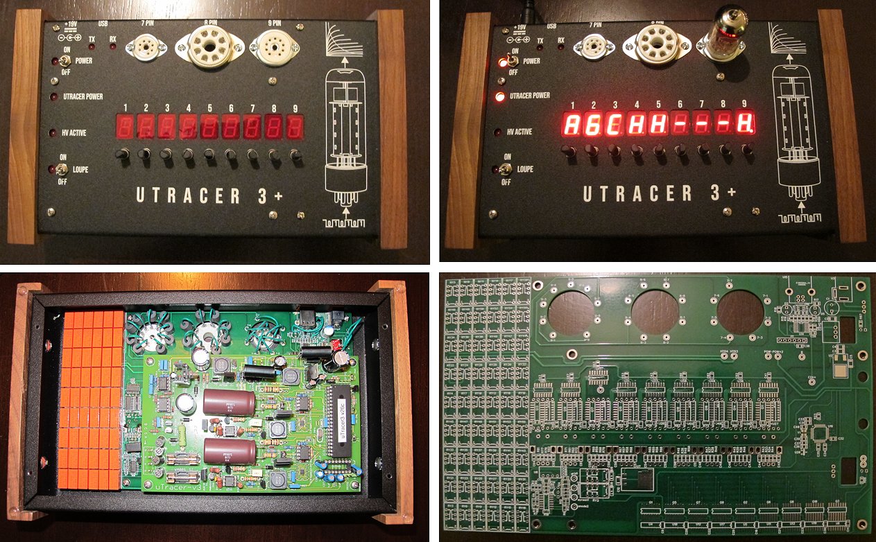
Ronald,
I want to start by thanking you for creating the uTracer. I purchased one years ago and have used it extensively since. For a few years I ran a business designing and manufacturing guitar amplifiers along with performing repairs for local musicians. The uTracer was certainly a tool that stayed on my workbench as I used it regularly.
I originally had the pcb in a plastic enclosure that was drilled out somewhat sloppily and assembled quickly. I used the banana jack solution for configuring the tube sockets as many other have done and although everything worked well I had always wanted to design a better solution and one that looked nicer at the same time.
Over the last few weeks I redesigned and rebuilt my enclosure and put together a carrier PCB that interfaces with the uTracer and makes configuring the tube sockets easy. Here is an image of my new uTracer (please excuse the image quality. I am an engineer and not a photographer.
My idea was to package the uTracer in an enclosure that contains all of the tube sockets that I normally use and to give the user a convenient way to configure the signals that are sent to the tube sockets. To do this, I designed a PCB that contains 9 seven segment displays, 9 rotary encoders, and an array of high voltage capable relays. The user can configure each pin for what connection they want by turning the rotary encoder under the pin number and pressing the encoder to accept the connection. When the user selects their option the onboard microcontroller will trigger the appropriate relays and make the connections from the uTracer pcb to the tube socket. Here is an image of the uTracer testing the first triode in a 12AX7:
Here is a picture of the guts followed by a picture of the raw pcb that I designed.
The relay array on the left routes the signals from the uTracer to the tube sockets based on the user input. To control all of the displays and relays I used a STM32F373 micro controller. This controller is pretty over powered for this kind of application but it had the right number of input pins and coding for it was easy so I felt that it was a good choice. I also put an FTDI FT230X usb to uart ic on the board since I did not want to build a nice looking box and have a FTDI dongle hanging out of the back.
So I just wanted to share this project with you and thank you once again for making such a great tool. I look forward to what comes next!
Thanks,
Stephen Kraig
20th of August 2018 Rui Monteiro made a quick and dirty uTracer, I like it!
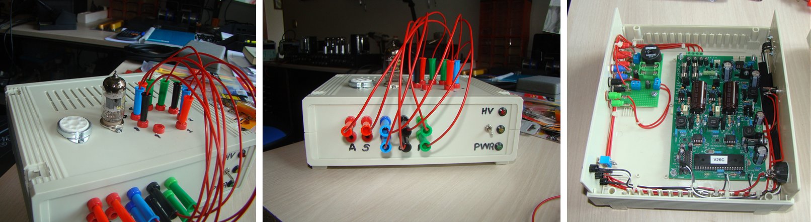
Dear Ronald,
I do really hope that you as also your wife Marie José, may be just fine.
As I promise you before here are some pictures of my version of your's uTracer. It is very far from the final version I'll pretend but I need it working for some work in hands, and I thought: "Simplify, Rui. Keep it simple. Just do what Ronald recommends.". Well it worth it. It is working very well, as expected.
There are some photos with the uTracer setup to test one 12AX7C tube. Then I send you some pictures of the internal connections. For the future, I have in hands one project to control the uTracer with a microprocessor (probably one PIC) to control by a menu all the connections automatically, to make it a little bit more intuitive to work with.
I do really thank you very much, for all the help and work you gave to this community.
Best regards,
Rui Monteiro
31st of July 2018 Josh reported his uTracer and has some tips for connecting a Bluetooth module!
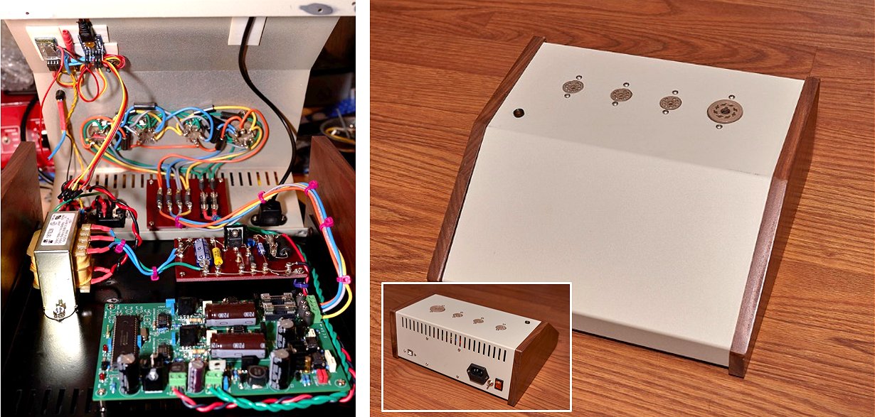
Hi Ronald,
This thing is finally (basically) done. I still need to do some labels and stuff for it, but the tester is completed and working as it should.
It works by either USB or Bluetooth (the toggle switch activates the Bluetooth, which disables the USB). The external LED shows the Bluetooth status – blinking when awaiting connection, solid when connected, etc…
My dedicated power supply also worked out great. It supplies regulated voltage with 1.5A available.
Now I need to learn the tracer tests for my tube types…and what the hell they all mean.
Thanks,
Josh
Josh has some tips for connecting a Bluetooth module that I am happy to repeat here:
Here's some tips regarding connectivity if you don't want to use the serial port, as the public info seems spotty: Don't use the 5 capacitors, IC chip, or dip connector for the serial port.
For USB only connect the Ground, TX, and RX. When using a USB board, don't connect the USB board to the PIC 5V supply, it isn't needed. For Bluetooth connect 5V, Ground, TX, and RX. Don't forget to adjust the voltage going to the BT board's RX port if it isn't 5V compatible. I did the LED trick to accomplish this.
Remember in both cases that the devices are communicating with each other so the TX from one device goes to the RX of the other and vice versa. If you connect TX to TX it won't work.
The trick to using both boards in mine is a simple SPDT switch that connects or disconnects the 5V supply to the Bluetooth board. Once the 5V is connected to the BT board, it overrides the USB board automatically.
Bluetooth may appear not to work in Windows. That's more likely Windows' fault than the hardware. Windows is annoying about this. You should first attempt to update the driver for the BT board. In most cases, Windows will install two COM ports for the BT board. Typically, the first (lower) port number is the number you need to use in the uTracer software. In Windows Device Manager, you may need to reduce the buffer size on that port before it will work.
Alternatively, you can test the connection with your phone, which is almost always easier to make a connection with than Windows. Once you've determined the hardware is okay, then go back to Windows and deal with that headache. ;)
28th of July 2018 Niclas constructed a beautiful no-nonsense uTracer!
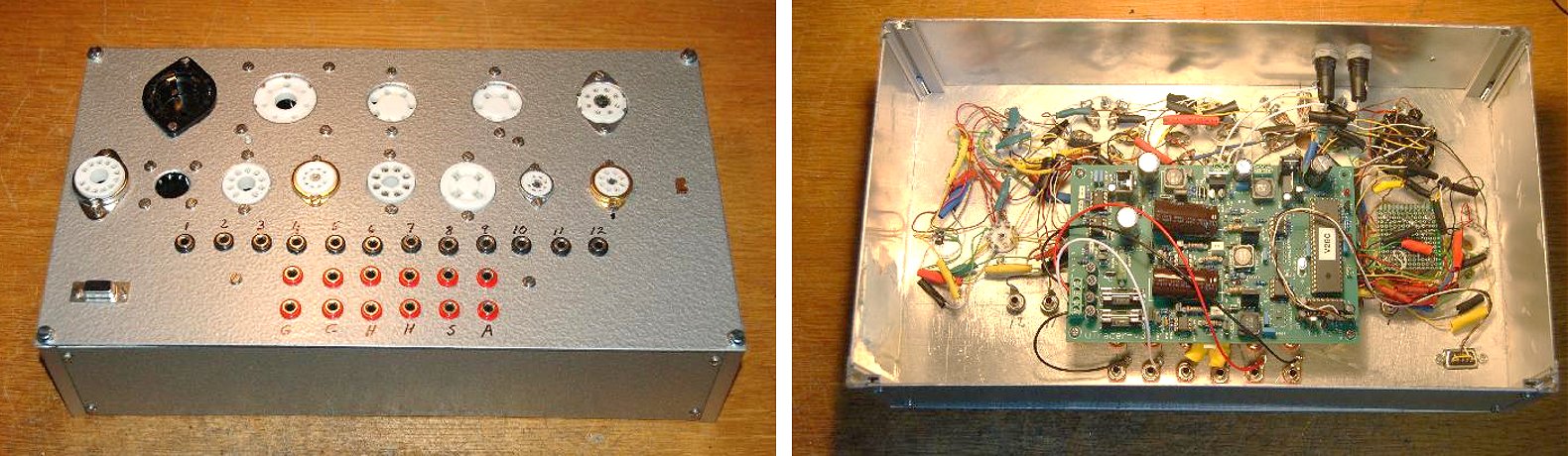
Hi Ronald!
I have put the tracer together now:
It was a bit of work to wire up all those tube sockets! :-)
I am missing one piece - it would be nice and convenient to have a female socket for the PC power supply on the tracer. I have searched the web for one of these, but without luck. I guess that I don't have the right word for it. Do you know where to get one?
With Regards,
Niclas
29th of July 2018 Kamil from Turkey turned his uTracer into a work of art, it even has an integrated PC!
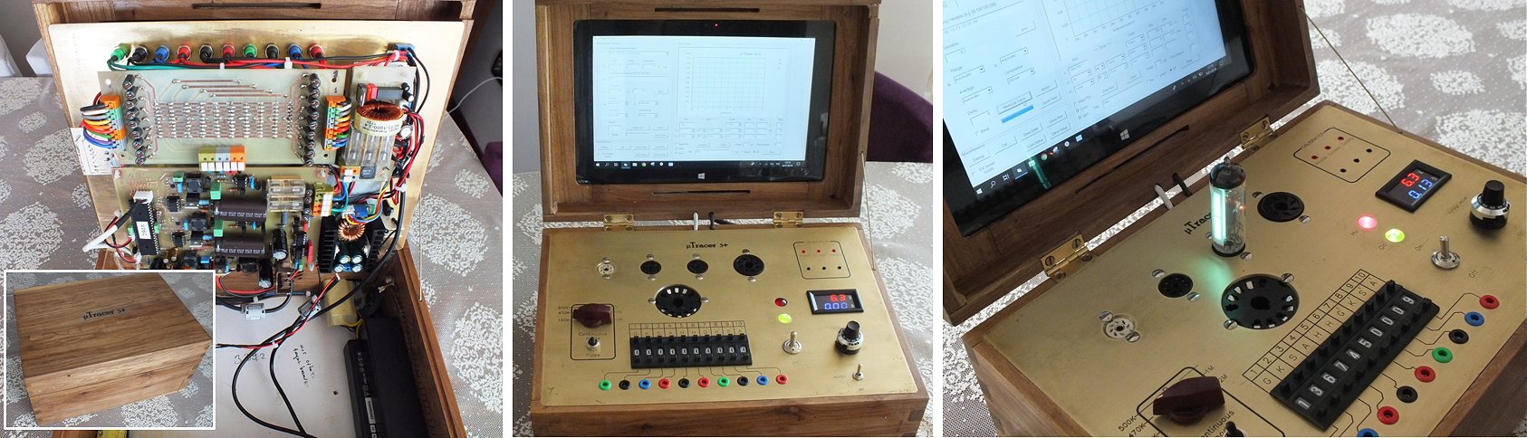
Hello Ronald and Maria Jose
First of all, thank you for your support. Project took a little long due to designing Upper panel, box and the pcb, and producing the pcb by myself. I preferred a well packaged design therefore put the pc inside the box Only thing left outside box is Bluetooth keyboard. Front panel is 2mm thick brass. Box is made of elm tree. I used buck converter for external heating. Right now everything works perfectly.
Thanks and best regards from Turkey Kamil
29th of July 2018 Collin Campbell is impressed by his uTracer!
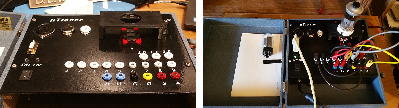
Hi Ronald
Please find attached a few photos of my first uTracer build. I used an old Tektronics CRT tester box for the enclosure and 3-d printed the panel out of black ABS. It has support for 7, 8 and 9 pin tubes directly, and a universal position for which I can 3d-print custom socket adaptors. In the photo, I have a GU-50 socket adaptor installed.
The tester works fantastic. I am very impressed. I have been doing some programming on Richard Harmans pUtracer. You windows GUI is the best for studying tubes but I have found pUtracer works beautifully for measuring large numbers of tubes quickly from the command line. It builds a database of the measurements which can be used to quickly match tubes at a later date.
I am planning to build the second kit soon, and I am very interested in configuring the second uTracer for low voltage tubes studies. I have a large number of Russian sub-miniature rod pentodes I am want to play with. I noticed in your blog you had done some work on configuring the uTracer for lower voltages. In that entry you had mentioned that a firmware update would be necessary. Can you tell me more about this configuration of the uTracer? Would you be willing to sell me a PIC with the firmware for low voltage operations?
Thanks in advance!!!
Colin
16th of May 2018 Josh’s uTracer has both a wired as well as a wireless connection!
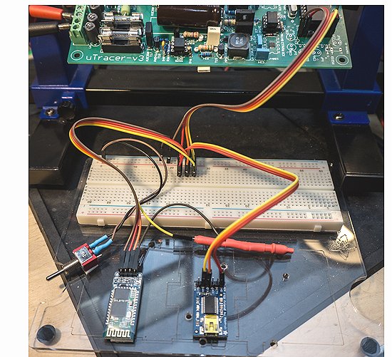
Hi Ronald,
I thought you might be interested in my final connection setup for the uTracer (even if the thing isn’t fully operational yet). The communication setup is working 100%.
I removed the serial chip and caps, and wired in similar to how you suggested for the FTDI 5V cable, BUT with some mods. I didn’t do your jumper or resistor mod as it’s not needed with this method.
TX on uTracer goes to RX on the comm boards and RX on uTracer goes to TX on the comm boards. The wires are reversed on the uTracer to keep it simple on the breadboard.
I have both a Bluetooth card and a FTDI USB board connected (tested with two different FTDI USB boards, both work fine). The trick is that I don’t connect the USB board to the +5V as it gets powered via USB anyway. The switch is to connect the Bluetooth board to the +5V when it’s going to be used.
Bluetooth off = USB board works. Bluetooth on, disconnect USB, Bluetooth works great (actually, I think Bluetooth worked either way when powered, but I disconnect USB from the computer to be safe).
Note: both of the USB boards I have support 5V logic. The Bluetooth board receive pin has a resistor + LED to drop the voltage down.
Thanks,
f
Josh
28th of April 2018 Remco de Vilder sent me a picture of his very nice uTracer!
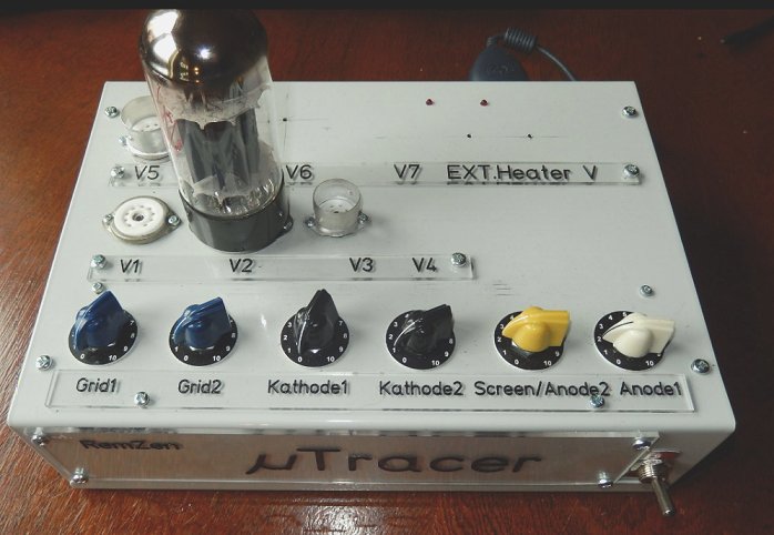
Beste Ronald,
Je vroeg eens in een post of de bouwers een fotootje wouden sturen.Bij deze,in bijlage vind je mijn bescheiden versie.Als meettoestel wou ik het niet al te opsmukken.Zoals je wel kunt zien is er plaats voor exotische buisvoeten ,alsook twee piepkleine gaatjes voor een external heater-supply,om groter te maken indien nodig. In een buisvoet zie je een 6550 zitten waar ik aan de slag wil gaan met een UL eindtransfo en gaf me alle info die ik nodig had.
Vele groeten van mij, aan jullie beiden,
Remco De Vilder
21st of April 2018, Bruce McBean reports another beautiful uTracer working on the other side of the world!
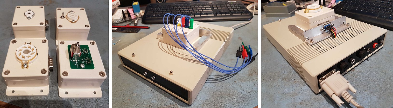
Hi Ronald,
It has been over 2 years since I purchased my uTracer kit. Construction had to wait until I completed my civil engineering diploma. Finally, I was able to complete the uTracer this week. I performed all the modifications to upgrade it from 300V to 400V. Happily it worked first go! I have attached some pictures which may be of interest to other constructors so feel welcome to place this on your testimonials page.
The uTracer PCB is installed in a plastic modem enclosure. I put connections at the rear for external heater as well as fuses and the essential serial connection. My computer is fairly new but it has a serial port on the motherboard. All I had to do was purchase and install a ribbon cable from the motherboard to the rear of the computer – a couple of dollars on eBay. The serial connection works perfectly and there are no drivers to install.
Tube sockets are mounted on flanged plastic boxes which have a 9 pin d-sub connector to mate to the uTracer. The flanged enclosure is guided into position between two pieces of aluminium with grooves. This was simple and cheap to make and it works well. I am interested in sub-miniature tubes and for these I made a small PCB with socket pins. Anode and grid are selected from the two halves with a switch. I built several other tube socket adapters for the tubes I am interested in. Finally, I built a test adapter for less common tubes using 2mm banana plug and sockets, some silicone wire and mini grab hooks. The DC from the reservoir capacitors is brought to two banana sockets as well. I am not sure if I will ever need that, but it was easy to implement – better to do things fully and correctly the first time than have to revisit later!
Warm regards from Australia,
Bruce McBean
6th of April 2018, Darrell reports another uTracer up and running in the USA!
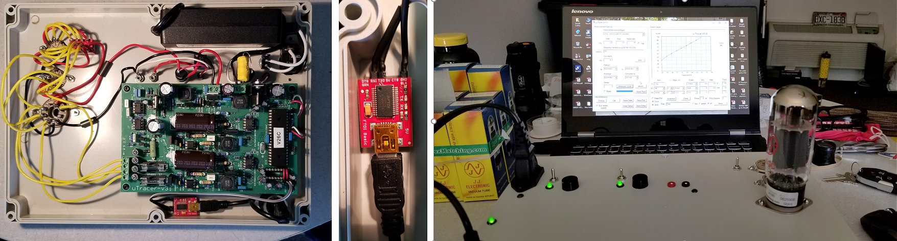
Ronald, I have finished the uTracer and wanted to thank you so much for all of your help and support.
Ferrite bead work will be completed when they arrive.
One more uTracer up and running in the USA.
Best Regards
Darrell Collins
5th of April 2018, David Boothe is very happy with his uTracer. He even started a new thread on it on Audiokarma
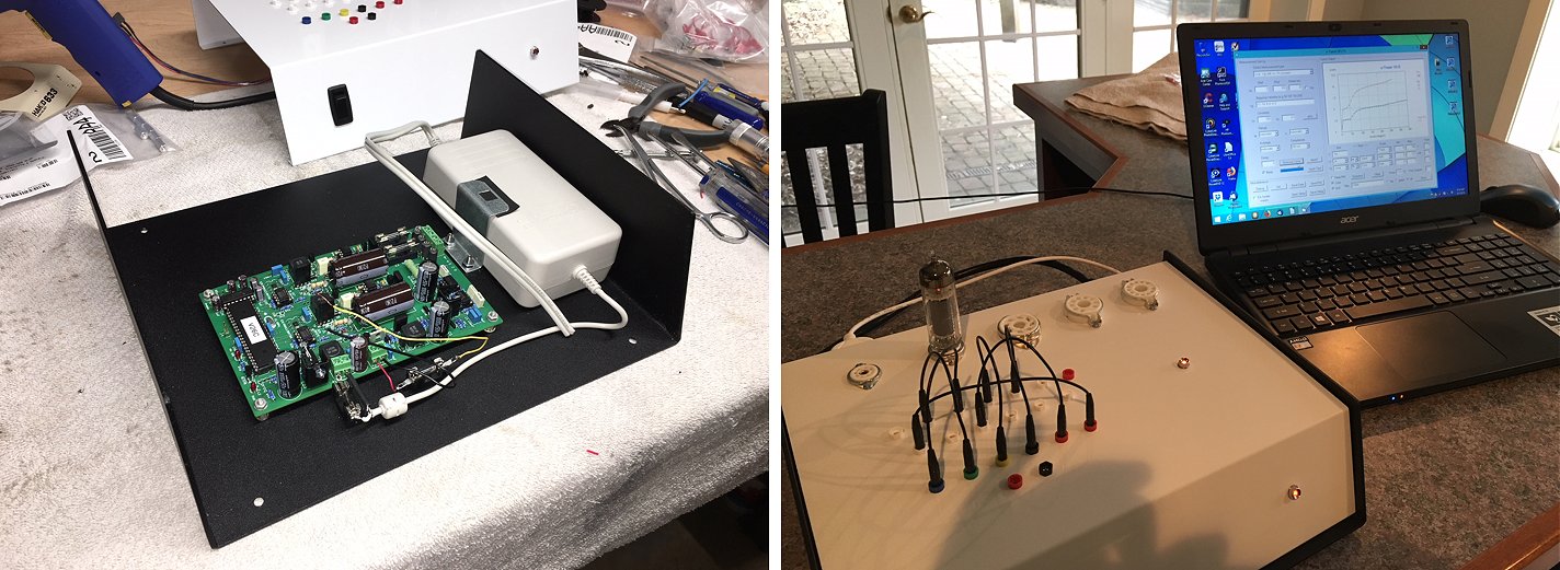
Dear Ronald and Marie-Jose,
I completed my uTracer build a couple of weeks after receiving the kit, delivered promptly from the Netherlands. The construction manual is outstanding and I completed the build with no issues using an 18V HP computer power supply. I bread-boarded the unit directly to a 9-pin and an octal socket for checkout and was very pleased that the uTracer worked flawlessly right from the start! The GUI was connected through an RS232 to USB adapter with no problems whatsoever. I really liked the step-by-step 'build and calibrate' process in the construction manual.
I then chose a spacious Bud Metal cabinet for the uTracer and mounted the board and the power supply securely on the cabinet base with a grounded AC power feed through and rear banana jack inputs for an outboard filament supply. I used the typical banana jack/plug connections (2 mm size) and mounted five tube sockets, including a 12-pin socket to test compactrons. I still need to label the controls and jacks, but I know what they are for now until I can find some attractive labels.
I have tested many tubes already and am quite impressed with the capabilities of the uTracer and the excellent GUI. The 'quick test' feature is outstanding and I'm getting acquainted with the very clever distortion measurement feature as well.
Ronald, thanks for developing and supporting an outstanding tool for the tube enthusiast! Some pictures of my uTracer are attached.
Dave Boothe
Landenberg, PA, USA
3rd of April 2018, after a few hick-ups, Nedo Fusari's uTracer is up and running!
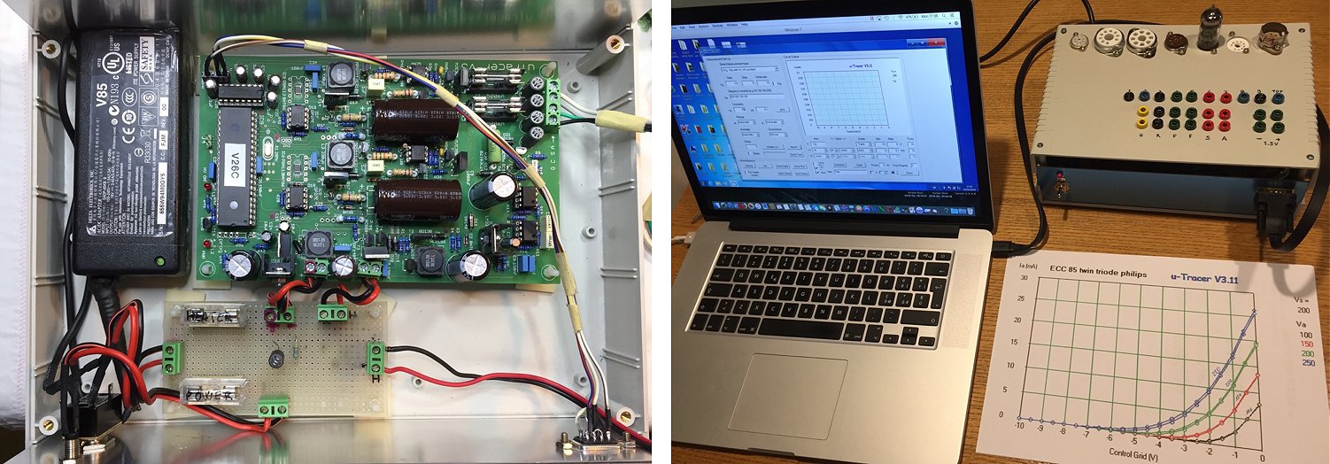
Dear Ronald
As you probably know, I received your uTracer the 20 of March 2018, and I worked many hours in the last 2 weeks to assemble all the components and to make the necessary circuit to test the Tubes .
Everything works perfectly but now I have to improve a bit the look of the internal connections to the uTracer, and those of my circuit made quickly to finish asap the work! Attached some photos of my simple construction using all your suggestions!!!.
(The program GUI is installed on my MAC Book PRO with installed the virtual machine Parallel 12 and Windows 7 pro. The cable to connect uTracer is a USB to RS232 FTDI (Ugreen purchased with Amazon).
During the assembly I had only a small problem during the test of the part 8, due to the faulty connection of the L1 inductor (Part 7) that had not given problems before in the test of the Part 7. The problem caused the system crash that even after repaired, did not restart well, even by switching off and on the uTracer many time, and also waiting few minutes. I managed to eliminate the problem by removing the IC 40 pin from the circuit and putting it back in position, after 10-15 seconds (in my idea to be sure to reset it) and finally after that all the tests were been performed correctly ! At the moment I have already tested numerous tubes (triodes, pentodes and so on, and printed charts and results in a perfect way, and also compared tube to match!
This experience it is very interesting and your project is truly exceptional and incredible and I still have to learn all its features. I think you are a real special and intelligent electronic engineer and I envy you a lot. I am a mechanical engineer and all electronic circuit create me a lot of trouble to understand it, all the time I need to study something new things, because my foundations in this matter are not very solid, but for me it is an exciting hobby.
Any way to finish my mail I want to tell you that I'm interested to test transistor with the new tracer, so I will study your information about it and I will answer you in case I need your help!
Thanks again for your project and I can say that I will continue to follow your web site to learn all what you have written.
22nd of March 2018, Frank Kloss from Dresden has a whole range of tube testers, but likes the uTracer most!
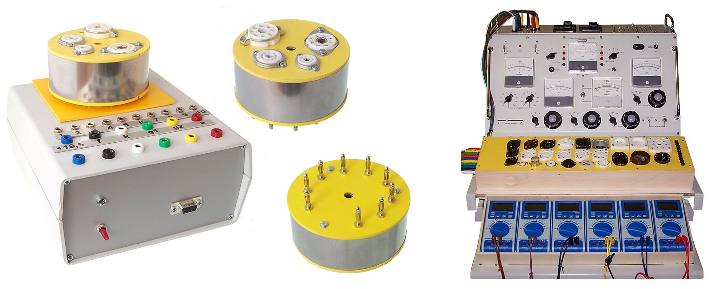
Hallo Marie-José, hallo Ronald,
Wir haben persönlich lange nichts voneinander gehört. Ich hoffe, es geht Euch gut – auch Eurem Jungen.
Ich habe nun auch nach langer Zeit einige Bilder von meinem µTracer zusammen gestellt. Ronald wünscht sich ja so etwas immer wieder. Ihr könnt davon verwenden, was Euch gefällt. Ich füge alle Bilder in diesen Taxt ein und gebe einige Erläuterungen dazu. Ich schicke die Bilder aber auch noch gesondert in einer Mail. Hoffentlich geht alles durch die „Leitung“.
Das ist mein µTracer, eingebaut in eine Box aus Kunststoff mit Blenden aus Metall vorn und hinten. Innen befindet sich die Platine. Wenn man die beiden oberen Schrauben vorn und hinten löst, kann das Oberteil angenommen werden. Man erkennt vorn die beiden farbig markierten Reihen von Buchsen, welche mit den zugehörigen Anschlüssen der Platine verbunden sind. Dahinter befindet sich die Reihe der Buchsen, welche zu den Anschlüssen der Adapter mit den Fassungen der diversen Röhren führen.? Das ist die Ansicht von hinten mit aufgesetztem Adapter mit Röhrenfassungen. Das ist die Gesamtansicht mit den farbig markierten Verbindungsschnüren zwischen den Buchsen zum µTracer und den Buchsen zu den Anschlüssen der Adapter.
Ich besitze ein Prüfgerät Metrix LX109A. Das verwendet für die Prüfung der jeweiligen Röhren verschiedene Adapter mit diversen Fassungen für die Röhren. Diese Adapter werden oben auf das Gerät aufgesetzt. Ich habe mir eine Reihe von Adaptern mit diversen Röhrenfassungen neu angefertigt. Außerdem habe ich eine Box mit diversen Fassungen gebaut. Diese Box kann ich sowohl an das Metrix als auch an andere Prüfgeräte – wie Funke W20 oder Neuberger RPM anschließen.
Es war daher sinnvoll, die von mir angefertigten runden Adapter mit den Fassungen auch für den µTracer zu verwenden. Dazu habe ich ihn entsprechend eingerichtet. Die Adapter lassen sich nun auch auf den µTracer aufstecken. Hier noch einige Bilder zu den Adaptern. Für den µTracer verwende ich ausschließlich die runden Adapter. Man kann natürlich auch die Box mit den Fassungen an den µTracer anschließen. Ich arbeite am liebsten mit den µTracer.
Für heute verbleibe ich mit lieben Grüßen Frank Kloss aus Dresden.
22nd of March 2018, Alexander Gurskii has his “homebrew” uTracer cased!
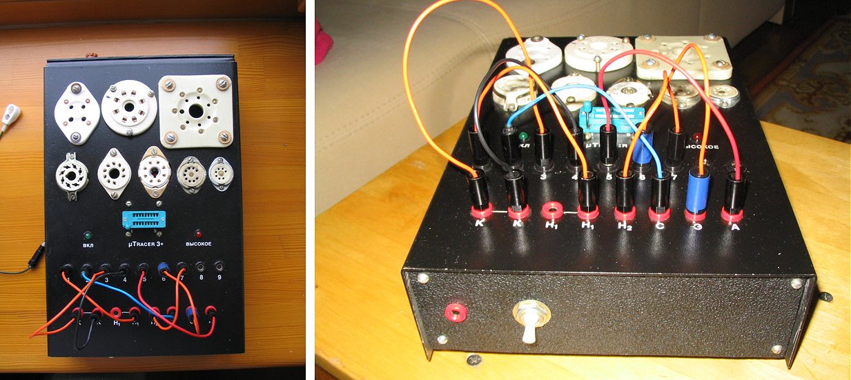
Dear Ronald!
This message is, first, to inform you that I finally finished my uTracer, namely, I packed it into a case. Although I tested it approx. 2 years ago, and you already placed it in your testimonial page, it was "not completed", and now it is really "ready for use". During the wiring, some problems appeared with tube oscillations (especially tubes with high transconductance), but now these problems are solved and even tubes with S=50mA/V are silent. I allow me to attach some pictures of the complete device. You may mentione some cyrillic letters on the front panel of it...
With best regards,
sincerely yours,
Alexander Gurskii
(Minsk, Belarus).
24th of February 2018, Dave Hanslip finished his uTracer and he is happy with the result!
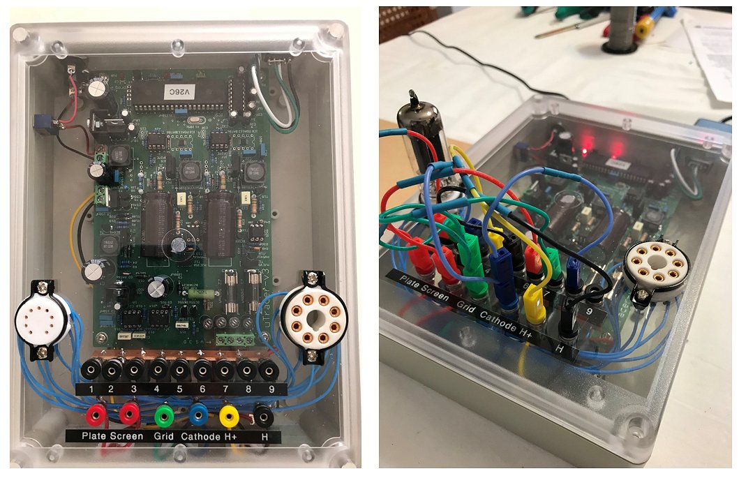
Hi Ronald,
Pictures attached. Very happy with the result!
Regards, Dave.
23rd of February 2018, Paolo Gramigna found a buddy for his uTracer!
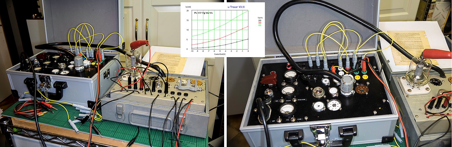
Hi Ronald,
I’m sending to you 4 photos of my uTracer3+ at work.
A few comments:
I’m testing a PL-177WA, a direct heating power pentode; not the easiest task!
That tube works well at 2000 volts, so I had to guess a way to obtain some meaningful curves.
I’m attaching two of them.
I’m using an external power supply for the heater, since that tube requires 6V and 3,5 Amp; probably I’ll have to recalibrate the heater supply, because it was unable to maintain the 6 Volts. on that load.
I connected one side of the heater to the cathode, as per instructions.
I had to use my MX-949/U socket adapter for that tube, as you can see.
About the casing: the three analog instruments were added since I had them available; I can see various voltages (plate, screen, bias) on them. I like to have an analog confirmation…
The aeronautical switch on the left doubles as an emergency shut-off (i had it available).
19th of February 2018, Helmut and Gerd sent me a few pictures of the beautiful uTracer they made together (I didn’t know there were so many tube sockets)!
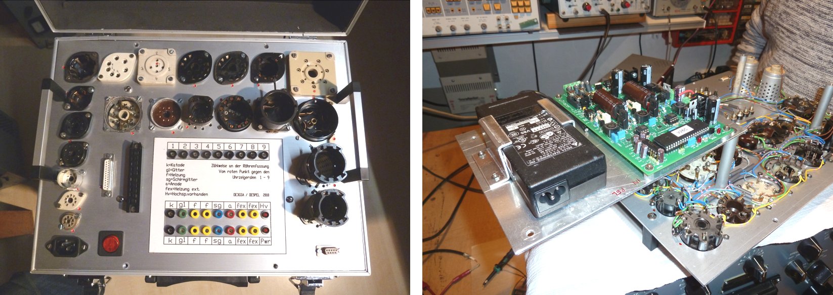
Hello Ronald!
uTRACER almost complete - I hope the pix are useful. It’s a bit loaded but as we work a lot with "boatanchors" we need old tubes from different origin.
Presently we work with Win7 and try to sort out problems with COM numbers. The ACER laptop with LINUX still makes problems (certainly my fault - hi)
We thank you for a wonderful piece of equipment. We are still learning a lot!
brgds Helmut & Gerd
18th of February 2018, Paul Abernethy turnerd his uTracer into a real sturdy instrument!
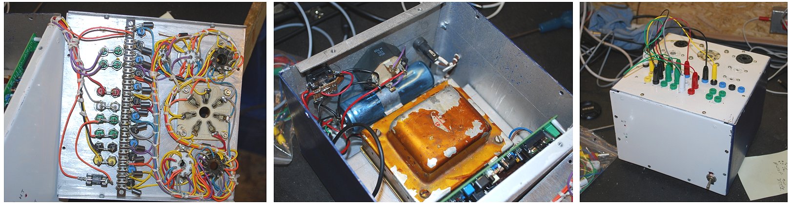
Dear Ronald and Marie-José,
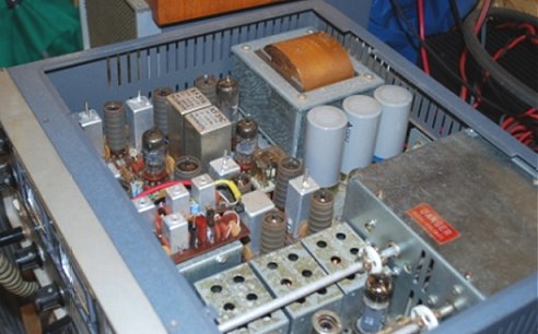 I apologize for not emailing sooner to tell you how happy I am with Ronald's design. As a retired Engineer, I was struggling to find a valve tester at reasonable cost and was debating designing my own. I was not familiar with the Boost Converter technique, my work involved radio transmitters with high voltage and high current supplies.
I am also a Radio Amateur and I needed a tester to check my stock of spares and the devices within this beast.
So I built your design and I have attached photographs of my efforts. I needed more filament current than the basic UTracer provides, so I used some items I already had: a rather large transformer and some other parts to provide the 6.3V AC and also the 19V DC.
I have already laid out a PCB for the positive grid supply modification, but the construction will have to wait for other projects.
Thank you for sharing this design.
Kind regards
Paul
14th of February 2018, Stephen Lafferty created an amazing “HP style” Vacuum Tube Analyzer, on his site Tronola he compares it to the uTracer!
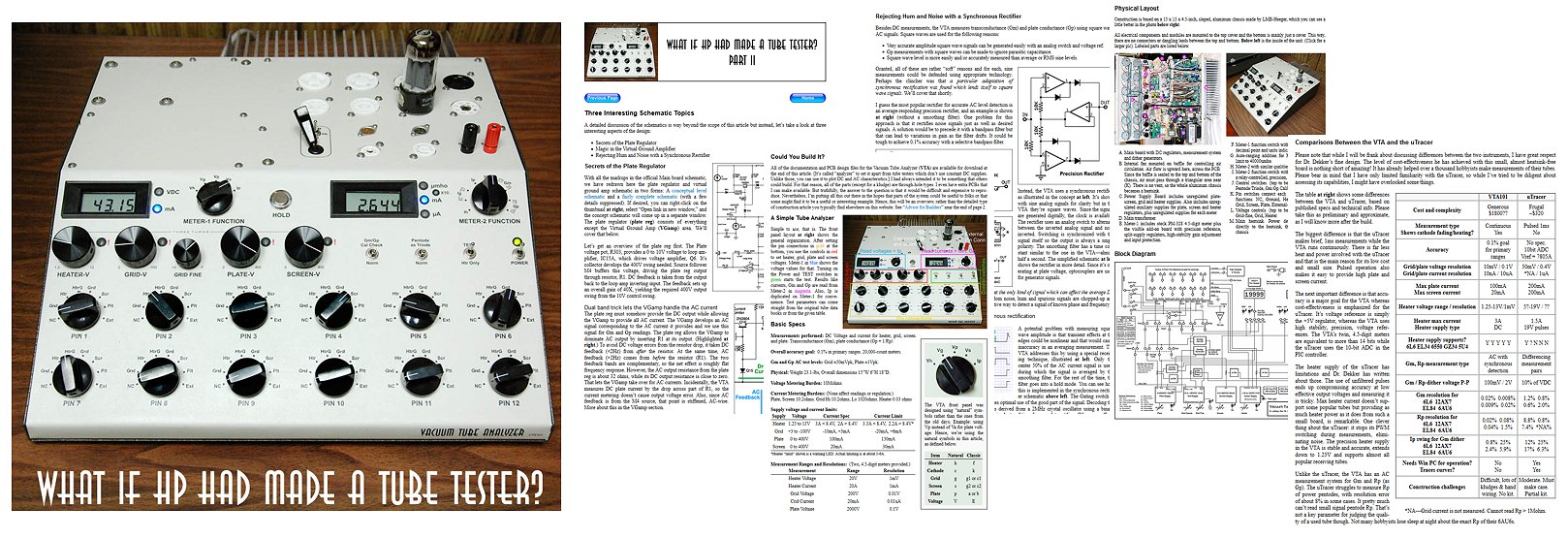
Stephen Lafferty posed himself the question “what if HP had made a tube tester?” Next he created the Vacuum Tube Analyzer (VTA). A stunning instrument that may well have set the standard in tubes testing! On his site Trenola, he published two articles (part1 and part2) on the VTA and he also compares it to the uTracer. Highly recommended!
13th of February 2018, Roger is one of the first builders of the uTracer and he now works at AK Modul-Bus where he made a YouTube movie demonstrating one of their products, and the uTracer!
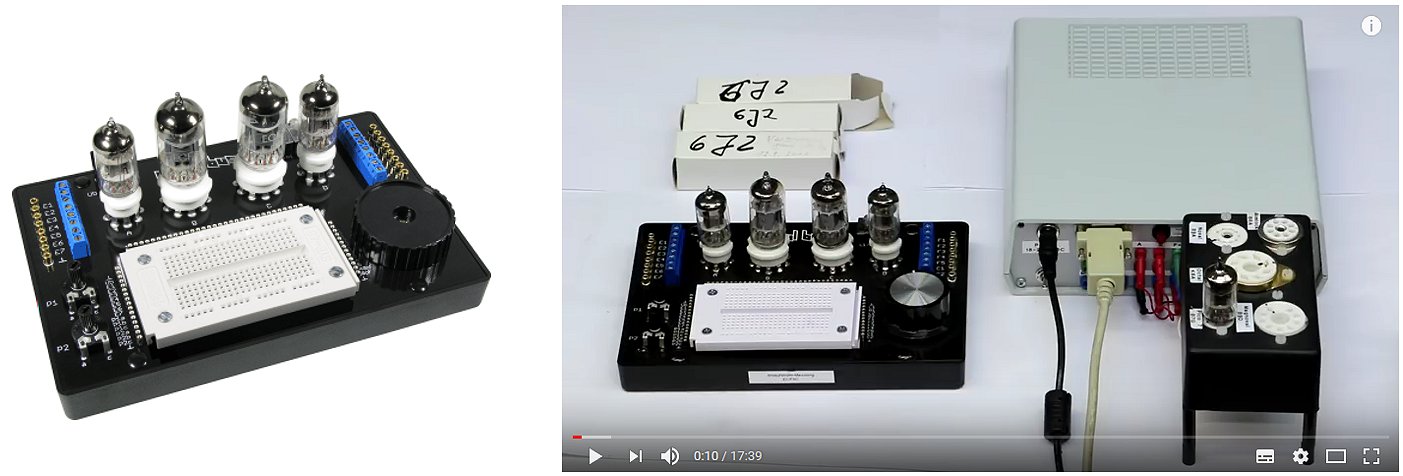
Roger from Germany was one of the first people who built the uTracer completely from scratch! He actually wrote the first testimonial in September 2012 that you can find completely at the bottom of my testimonial page. He now works at AK Modus-Bus www.ak-modul-bus.de/ a German company that makes kits and modules for electronics hobbyists. For their YouTube channel Roger made a demonstration about how they select tubes for our tube-experimental kit RT100. About half the video Roger is showing off his uTracer!
Also watch his interesting video where he is demonstrating the spread in “starting-current” in tubes for low voltage experiments.
11th of February 2018, Erwin Sluiter finished his uTracer and a brought a monster back to life (heater 5V, 10A) !
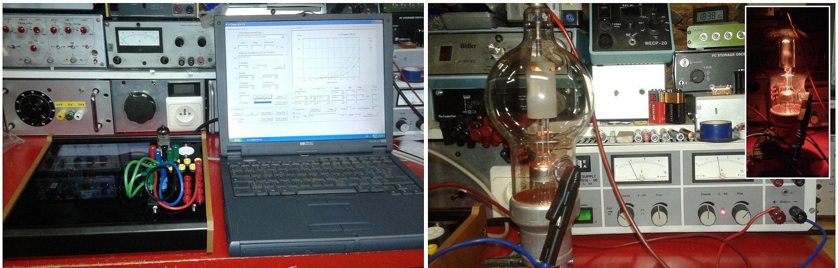
Dag Ronald,
It took me a while to finish the build of the uTracer (finding a nice enclosure etc., I finally used a box holding a display showing the cue number from a shop), now I just have to do the labelling
I did a test with an ECC83 and a 250TH (triode which needs about 50W heater power)
In the attachment are some pictures
Groeten,
Erwin
10th of February 2018, Albert Valiente from Barcelona sent me a report and some pictures of his amazing uTracer!
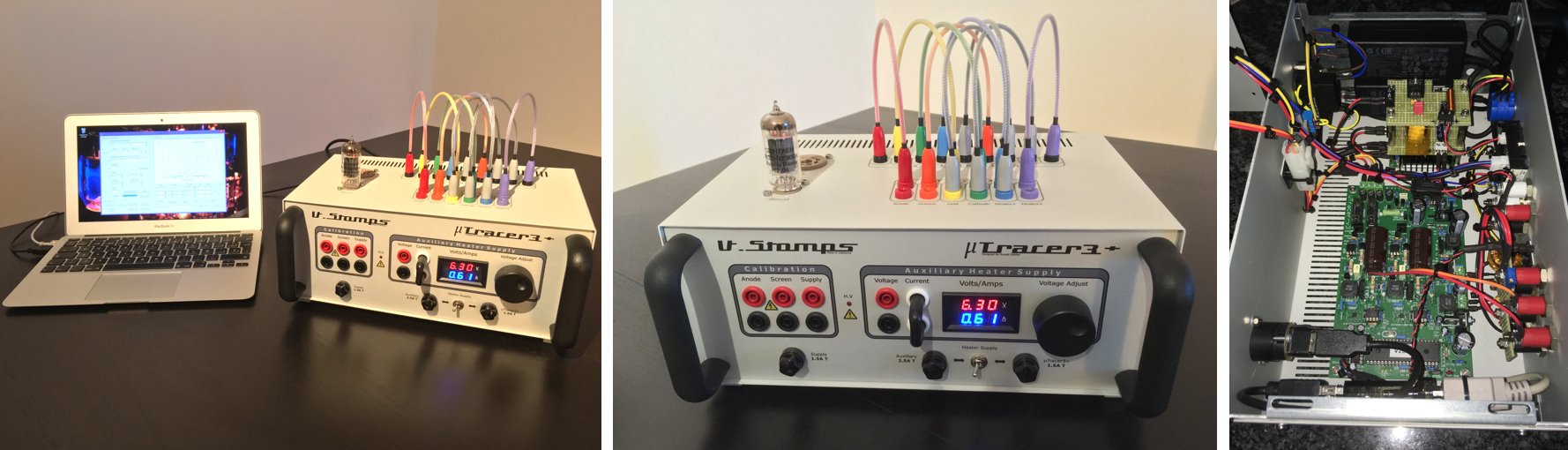
Hello Ronald and Marie-José ,
It’s been a while since I ordered the uTracer3+, but finally is completely finished and working absolutely great. The uTracer3+ is a very powerful tool that will help me to improve my tube designs for sure!
What I’ve done here in my version is use two laptop power supplies. One for the uTracer itself, the other to power the auxiliary heater supply. Both power supplies could be earthed or lifted from earth, while the case is always earthed. I took a lot of care about the earthing scheme to prevent ground loops, just leaving one earth point connection to chasis. Auxiliary heater supply is controlled by a powerful buck converter, adjusted by a 10 turn power potentiometer assembled in the front panel. One of the issues that was to be addressed, was the correct display of the voltage/current on the front display. With low current tubes (300mA) voltage/current was quite ok, but with big tubes like a el34, voltage drop was too large. So I rewired the thing until I got perfect match of voltage/current between the meter and the tube socket with a tube inserted. I also installed a circuit to the front panel to set a virtual ground reference, to direct read out the high voltage value generated in the boost converters, so no need to write down the idle voltage in the high voltage capacitors and then subtracting it from the final reading. It works quite well, and calibration is even faster.
Click here to read an extensive description of how these modifications were implemented!
Here you have the pics of my uTracer3+ version, hope you like it!
Very best regards from Barcelona.
Albert Valiente
10th of February 2018, Tomas Lannestedt from Sweden earlier reported his uTracer working and he has it now in a beautiful case!
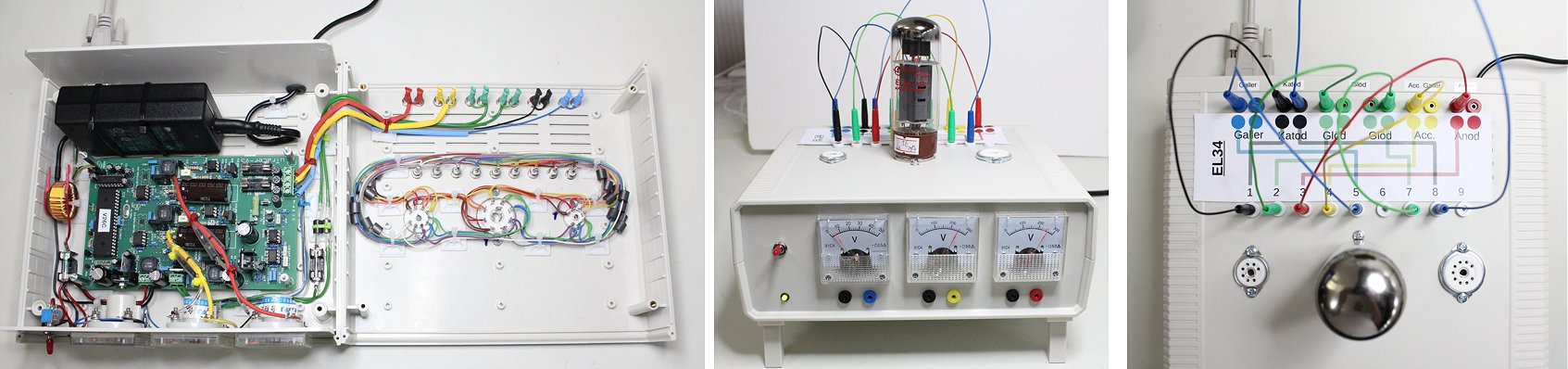
Hi Marie-José and Ronald,
Just to let you know, a few weeks back I Finnish the uTracer build, now in a case. See attached pictures.
BR
/Tomas
10th of February 2018, Joe Rossi sent be a “sneak” preview of his beautiful uTracer!
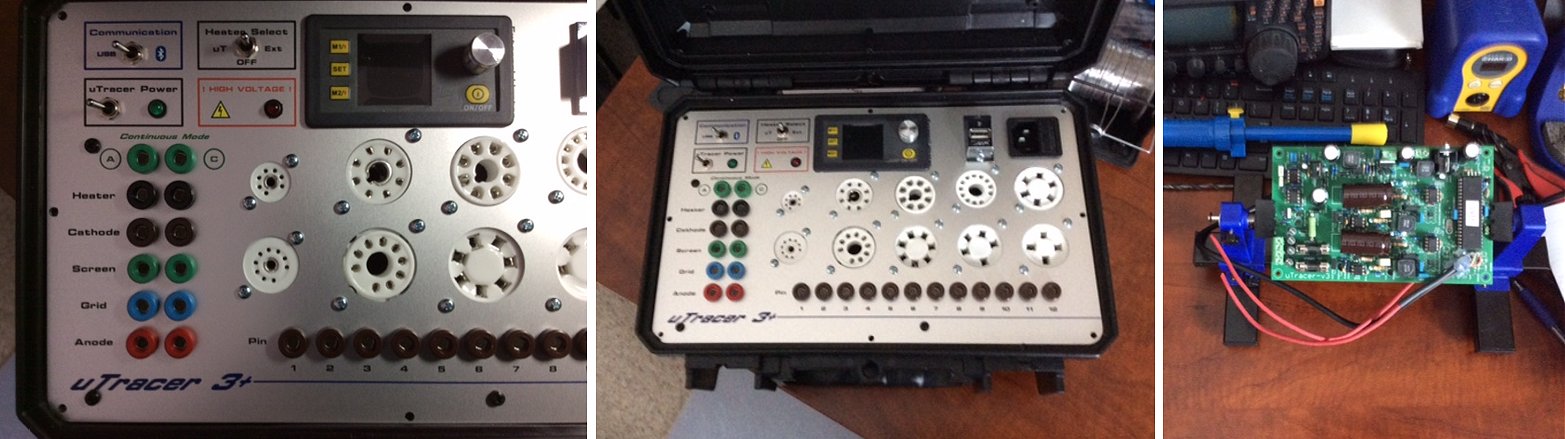
Hello Ronald & Maria Jose!
I saw your request for more photo’s, so this is a sneak peek of my uTracer. Although the board is complete, tested, and working, putting it into the case is taking time due to an illness in the house. Priorities first! But I did want to brag a little. The uTracer was so easy to assemble using the instructions you provide. Reminded me of when I was much younger and built Heathkit and Knight-Kit equipment and radios. I must go, but I will send you more info and clearer pictures soon. God Bless you both!
Joe Rossi, USA
9th of February 2018, Teo from Spain has been using his uTracer over the past two years and he is very satisfied with it!
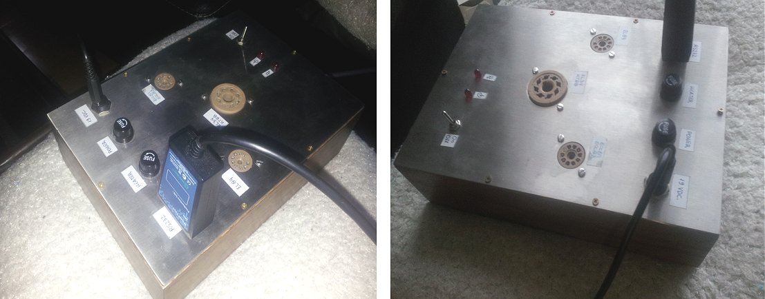
Hi Ronald ,
I´m very busy this week, but here you have my review of your fantastic U-tracer :
"I´m a real tube lover. All of my music device are with tubes and I love the way NOS tubes reproduces the music.
The music is part of my life so I was needing a reliable tube tester at a good price and thanks to Ronald I have mine.
I buy NOS tubes around the world and I need to select the best ones for my gear. Now I Can get the best of the sounds thanks to the U-tracer.
I have been able to check how the U-tracer works and it is fantastic. I have some honest dealers that send me tubes testing with Amplitrex. I can assure that U-tracer makes the same job in a minute.
I have been using the U-tracer 2 years and never i have had problems with it, so to get an U-tracer is one of my best decisions in my life. I think Ronald is fantastic, Thanks for giving to the music lovers the light we have been needing.
Best Wishes from Spain
Teo
4th of February 2018, Peter from Brisbane reported another uTracer working on the other side of the world (Brisbane)!
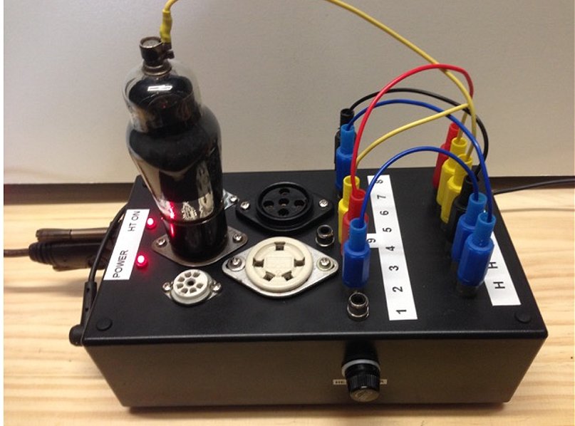
Hi Ronald,
As requested here is my uTracer in its box testing a WW2 vintage VR100/KTW61.
It works fine once you get past the usual windows problems with com ports & usb to serial issues.
I am very pleased with the uTracer, it was easy to build from the instructions, and is quite easy to use. I use the save set up/ pins feature a lot to make setting up any test very quick.
I might build the grid voltage zoom board, but there is not much space in my box.
Regards
Peter
(in Brisbane, Australia)
2nd of February 2018, Dieter has squeezed a lot of electronics in a tiny box! Beautiful!
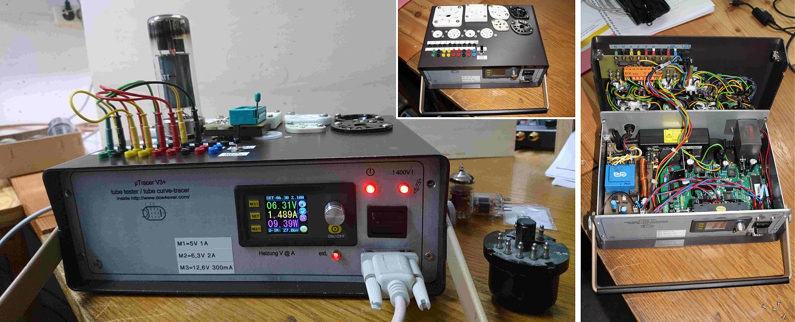
Hello Ronald and Maria Jose,
Thank you for the message. The uTracer works very well, the structure is, as has been said many times, prepared in great detail by you and no problem. Thank you very much :-) It will be a wonderful addition to my measuring instruments.
My uTracer V3 works both with internal or external heating according to your suggestion, the additional display is a Drok over which I lead the external heater. Voltage and current I can freely adjust or program with the internal memory locations before. The idea came from a uTracer report on Google+; Enclosed a few pictures.
Thank you again to everyone involved in the development of the uTracers.
best regards
Dieter
2nd of February 2018, Georg has been testing some ancient tubes and made himself a positive grid bias (only works for very low currents)!
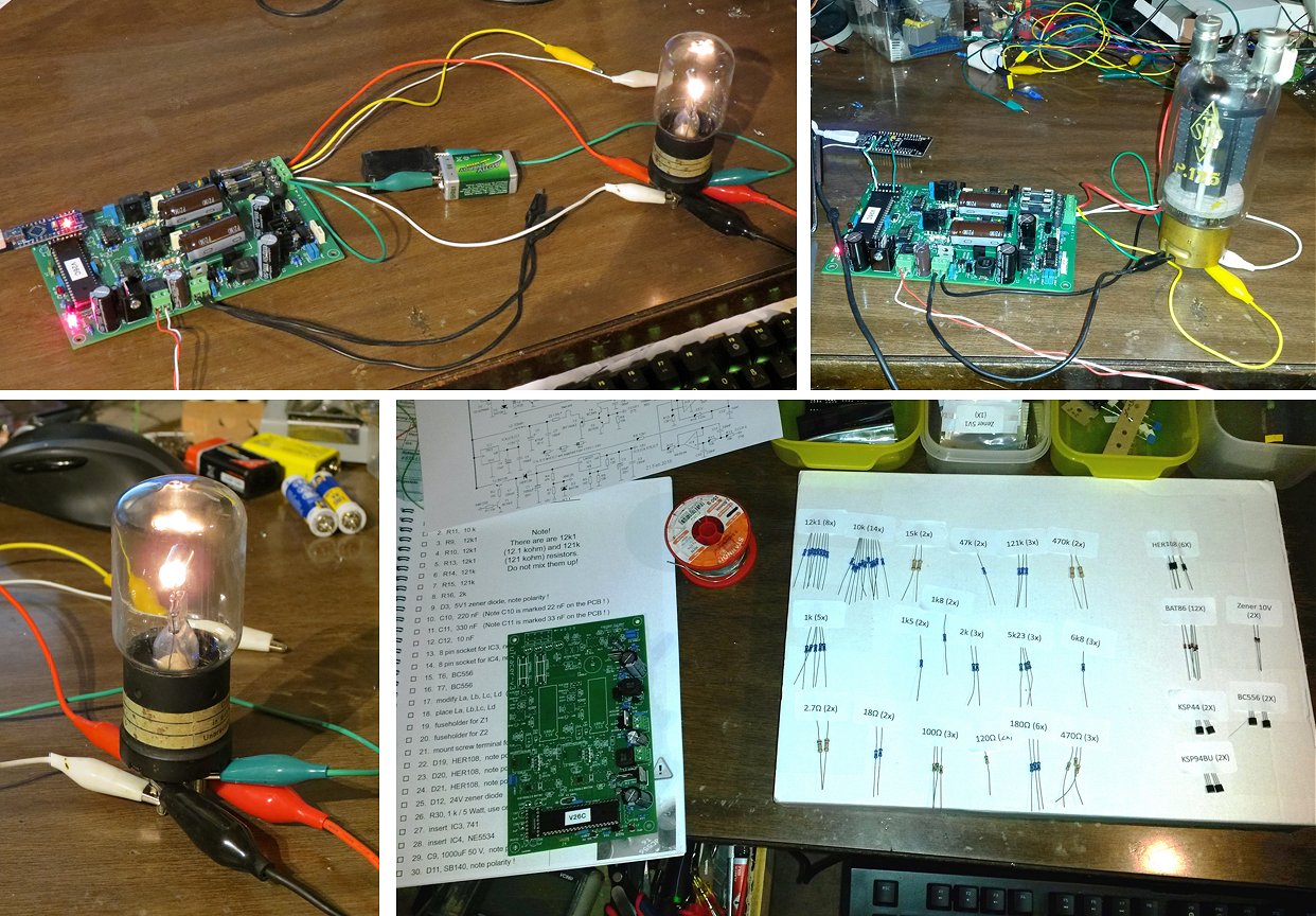
Dear Ronald,
thank you for your friendly invitation to share my first experiences with the u-Tracer. One of these is closely linked with your new solution to broaden the range of the grid bias. When I finished the uTracer last Sunday, I quickly encountered precisely this question, because the most antique tubes from 90 to 100 years ago were regularly operated well into the positive grid range, of course because otherwise the anode currents would have been just too low. It was not unusual to use positive grid voltages of 10 Volts and more, to use the current range up to the saturation emission of the tungsten or thoriated tungsten filaments. As I happen to own a few specimens of that kind, I was wondering how to adapt the uTracer for such measurements. I decided to try to apply a constant voltage between the grid output of the uTracer and the grid terminal of the tube. Two 9V - batteries in series did the trick, as you can see in the enclosed pictures. I used the global multinational super-flexible reptile tube socket adaptor, a.k.a. alligator clips (in German Krokodilklemmen, how are those named in Dutch? (Ronald: krokodillenklemmen!)) for all connections (Until I find the time to build a regular tube testing rack with the required dozen or so different sockets, I will stay with the reptiles) . Using this shift in grid, I could reproduce the official "Kennlinien" of an EVE173 from 100 years ago with almost unbelievable precision. This works of course only as long as the grid currents are in the fractions of mA. These results convinced me even more of the outstanding quality of the whole concept of the uTracer.
I have also added pictures of the first tube tested, a NOS RV12P2000, which also performed according to specification for all parameters. I was a little sceptical at first regarding the pulsed heating power, but all my experiments showed no negative effect on the performance of the tubes, even for directly heated filaments of 2,4 V at 60 mA. 19 kHz seems to be too fast to experience temperature fluctuations even for those filaments of a few microns thickness.
The "new born" uTracer had also to show some heavy lifting feats - the 100W P.125 shown was tested to up to 200 mA at 400V, with no problems at all. Quite a number of tubes of all types have been tested in the last few days, with some very interesting results, i.e. the very pronounced "kink" of the early "Schirmgitterröhren" like the VALVO H4125, that you couldn't reasonably operate at plate voltages below the screen voltage.
During the optimally guided assembly, I picked the required components from the beautifully labelled zip-lock bags, leaving the unused ones in the bags. This safely excluded the risk of accidentally mixing i.e. resistors of different values, but was very time consuming, first for the search of the correct bag and then from opening and closing each bag every time a component was taken. A better solution was needed, with the following provisions: a.) no potential mixing of components b.) easy finding of the right component c.) unequivocal identification d.) quick retrieval of single items . My solution is shown in the last photo. Thankfully, the labels could be peeled off the bags quite easily and had enough stickiness to keep the components in place on the backside of the box, in which the kit was sent. I’m thinking about applying a patent for that :-).
To conclude: the uTracer has surpassed my already high expectations by far. I will follow your further ideas and developments with high interest. Keep up the good work!
Best regards and all the best
Georg Grossmann
1st of February 2018, Dave is still busy with the construction and enjoying it!
Hi Ronald,
Thanks for the update. Even though I received my uTracer kit back in August last year thanks to work, holidays and other projects I've only just started assembling it.
I have to say that this is the most thoroughly thought-out and documented kit I've ever had the pleasure to build! I particularly like the "build a section and test it before continuing" process. I've already discovered a problem while testing the heater section (I used your suggested approach but L2 was only soldered on one side despite appearing to be solid) that would actually have been impossible to fix if other components had been in place. I'll be more careful with the rest of the inductors.
I didn't have an old laptop power supply and wasn't able to easily obtain one. A few years ago I would have had plenty of them. Fortunately I was able to buy an 18V 1.33A plug-pack. The other thing I didn't have was globes to test the heater circuit. Everything is LED these days. My local electronics supplier has 6V and 12V 300mA globes but rather than making a special trip there I threw caution to the wind and tested with a small triode.
I'm enjoying the assembly process so much it will be a shame to finish! I'm still thinking about tubes I'll be wanting to test but it will probably be limited to octal, noval and the likes of 2A3s and 300Bs. When I've finished and tested the PCB I'll look at enclosures.
I will send a picture when I have finished!
Thanks and regards, Dave.
31st of January 2018, Brice is pleased with his uTracer and as some useful suggestions for a possible PCB redesign.
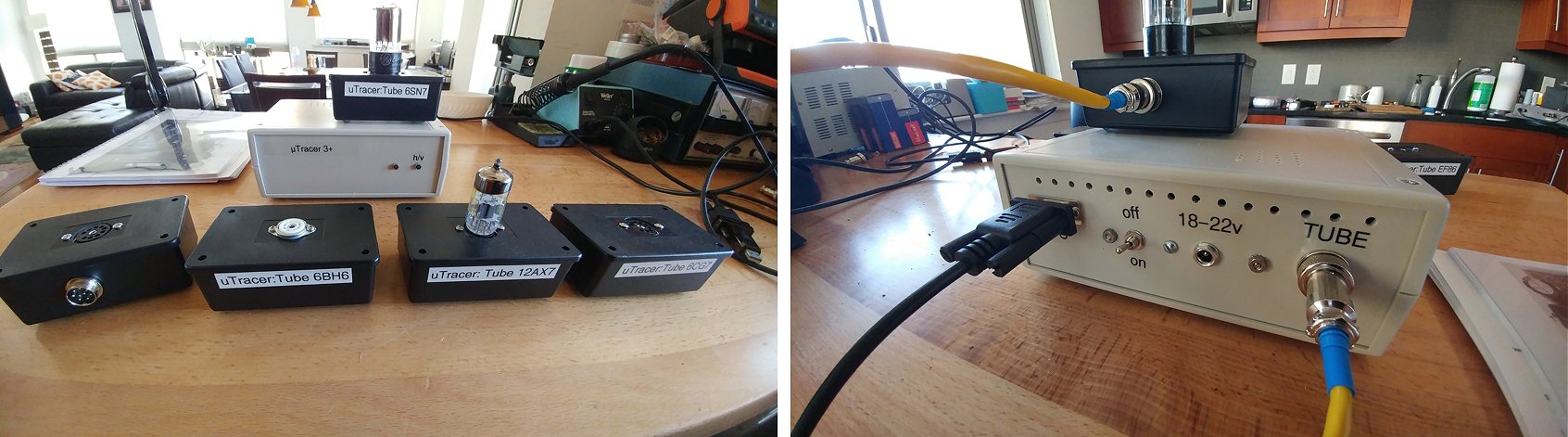
Hello Ronald,
This is Brice from France.
I just got your news update. Thank you for sharing.
Here are two pictures of the Tracer I've build. I decided to simplify my life when I need to check a tube, so I've build enclosures for each type of tube I am using. 1 for the 12ax7 family, 1 for the 6CG7, 1 specific to the 6BH6 and EF86 tubes, and one for the 6SN7. The power tubes will come later as I run out of ABS plastic box but it will be easy: EL34/KTxx family, 1 fr the 6L6 family and one for the EL84. If I run into exotic tubes, I'll use a test board which I can wire the way I need.
For the kit itself, your documentation is bullet proof. The build was easy and logical. The step by step is good to build confidence in your work. I did not make mistake and the kit ran at first try.
Now my comments (please take this as non-critical but more questions/ideas):
- The boards has last minute hacks with components mounted on top of each other and on the reversed side. I think another iteration of the board is needed to remove those modifications.
- The board's pad are very small. Soldering by hand require a very precise amount of solder to have a clean solder. Not everyone has that skills. Why don't you make the board a little bit bigger? Also 400V requires a 1.5 mm trace clearance to avoid capacitance leakage.
- Adding a DC heater LED indicator.
- Adding a power diode to prevent damages when reversing the + and - of the power supply.
- The heat sink provided for the LM317 is not optimal and too small. It gets very hot and I did not feel comfortable with it. I bought others and made it fit by mechanical means as the capacitors are on the way of "regular" heat sink. I was close to remove it from the board and put it on its own on a big heat sink. If it was positioned along the side of the board, it would be easier to mount the heat sink of your choice.
Now an important question: Is there a way to prevent damages in case of a short of plate to grid?
I think all the other cases are covered, but between those two points?
Ronald: The grid circuit is plate to grid protected by diode D21!
Ron, you've done an awesome job with this tester.
It's a must have tool and since I have got mine, I realized that many of my expensive NOS tubes are in fact really close to Old and Dead then New :))
I am an active member on AudioKarma.org and advocating for it.
Thank you for all.
Cheers,
Brice.
31st of January 2018, Vladimir’s uTracer is working and in a beautiful box!
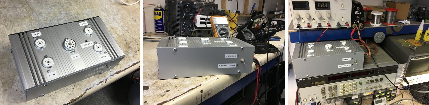
Hi Ronald
uTracer works well!! I like it!.I use it mainly to pairing tubes.... sending some photos.
Thank you
and best regards
Vladimir
28th of January 2018, If you can read Japanese, you can follow the construction of Kanji Kayanuma’s uTracer on his website.
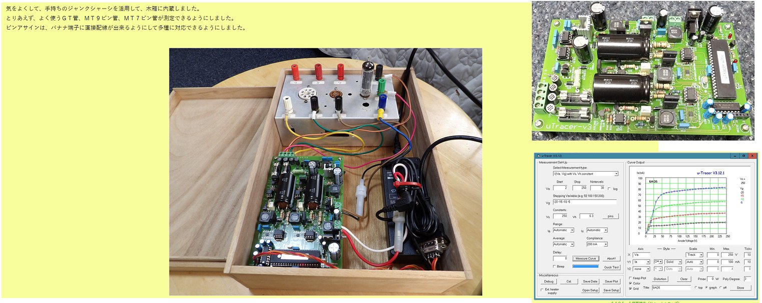
28th of January 2018, Eric Steelreath sent me a few pictures of his fine uTracer!
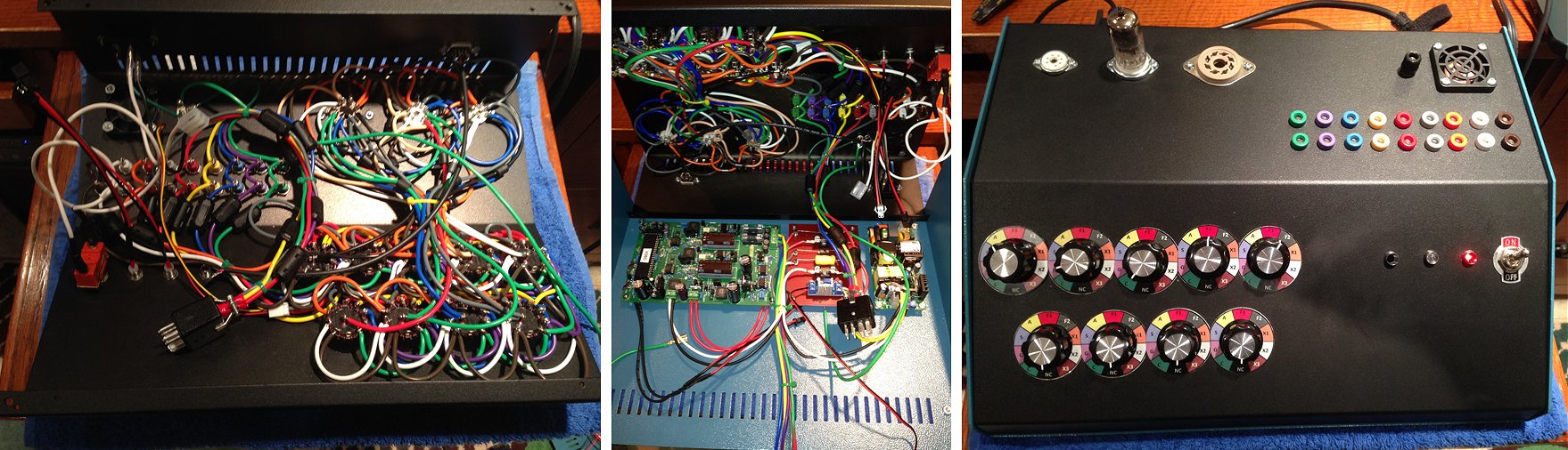
Hello Ronald,
I finally completed the unit. On the bottom, you'll see the uTracer main board; a turret board with fuses, filters, buck converter 12VDC fan power); and a 19V PSU (Cincon CMF101S200). The top has the switches, banana test points, tube sockets, and fan. All of the connections between the top and bottom are plugs so the top can be totally removed from the bottom for constructions and maintenance if needed. I tried to keep all the wiring, switch plates, banana plugs colour coded to help with the construction. Soldering the switches and sockets was tedious...
Regards,
Eric
26th of January 2018, Davide from Italy sent me an extensive photo documentation of the construction of his amazing uTracer!
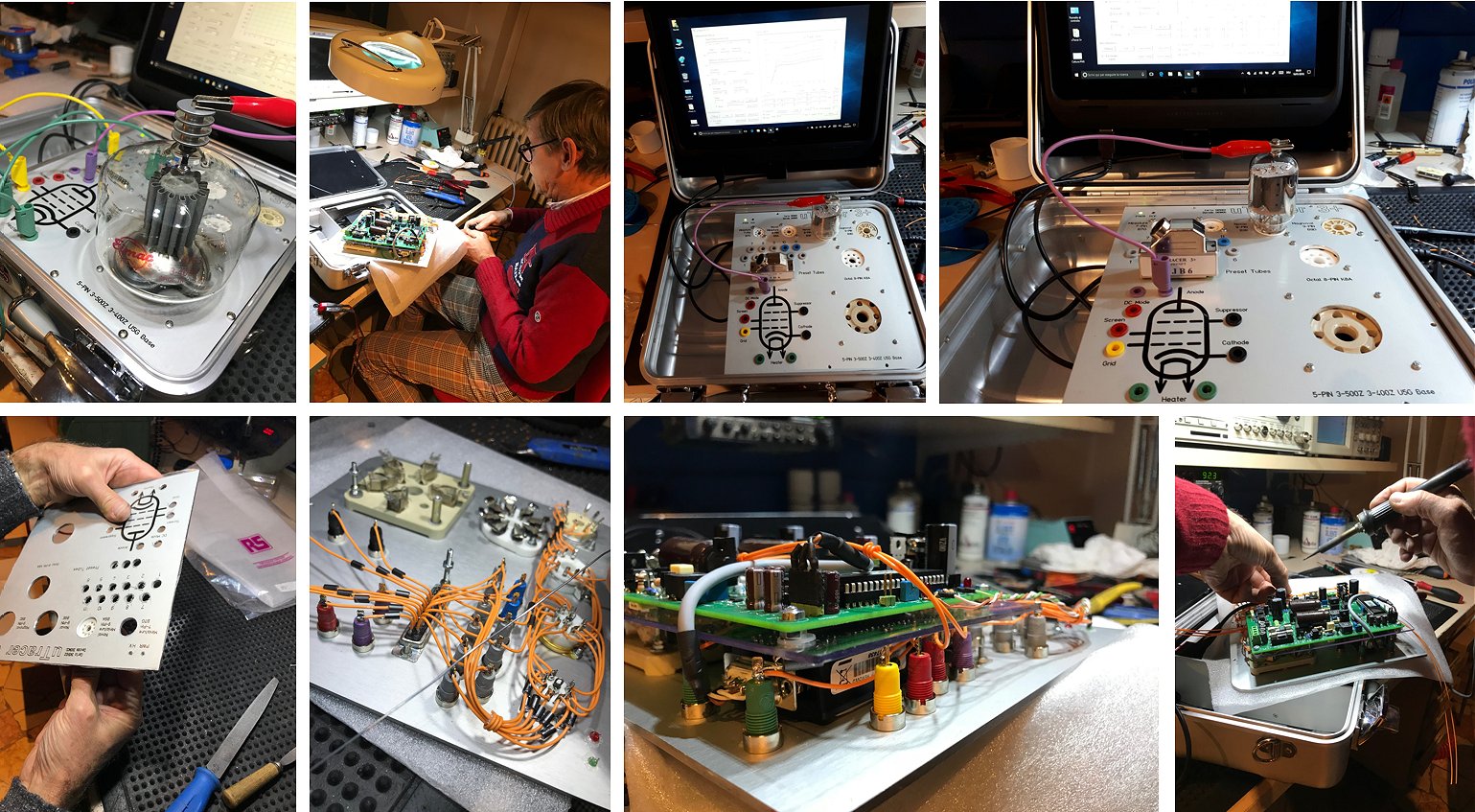
Hi Ronald and Maria José,
I send you the link to share and view our realization of uTracer +3. The electronic part, thanks to your perfect kit, has been assembled and tested in just a few days. Excellent the quality of the manual, the components, everything is perfect. A further challenge commitment was the mechanical and electromechanical realization. We have created and assembled everything, including an HP 900 G1 tablet, in an all-in-one solution in an aluminum case - small in size ...
Dear Ronald, I do not speak English well and that's why I'm a big fan of "one image is worth a thousand words" ... With the link here in attach I give you available on my OneDrive images a video of these months of fun work in case you want to post some of our photos on your beautiful site.
A big, enormous thanks to Carlo - IN3HDZ - a great technician, unfortunately on surface-mounted micro-components, but also a great friend of mine who shared my passion for thermionic tubes with me, realizing most of the project.
Now my part come in the next days, I will have to study the user manual well and also deepen the theory and characteristics of the tubes. Thanks and best regards from Italy Davide - IN3MOD
Ciao
Davide
24th of January 2018, Eric Johnson is convinced everybody can build a utracer!
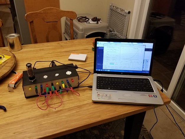
Ronald
Thanks again for your help, please disregard message from earlier today, found that heaters weren’t working due to blown fuse, able to get measurements now.
Thanks again for your kit, this was easy to build, biggest fear I had was the case, but I built that in less than a weekend. Looking forward to testing some old tubes I have had sitting around.
I have attached a photo, please reassure anyone who asks that if Eric Johnson can build and get to work, so can pretty much anyone!
Cheers, Eric Johnson
18th of January 2018, Lars Gustavsson from Sweden has been using his uTracer for quite a while and he is very satisfied with it!
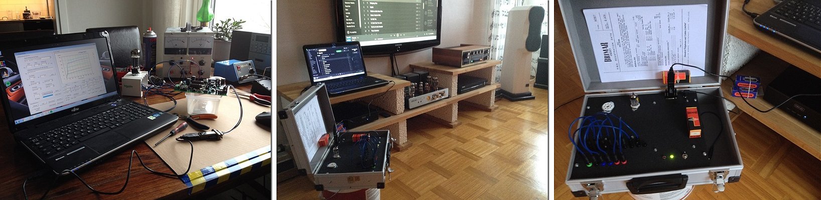
Better late than never. A kitchen table and a borrowed power supply and the project was running. No problem at all with such good construction description. It became a basic design for control and matching of tubes for my tube amplifiers and easy to develop if I need. SO USEFUL!! Thank you for your nice and great job Ronald, I am very pleased. All the best to all of you!
Lars Gustavsson Sweden
14th of January 2018, Geert Kuyken from Belgian finds the uTracer extremely useful for his NEL Guitar Amp Servicing business! (in Dutch)
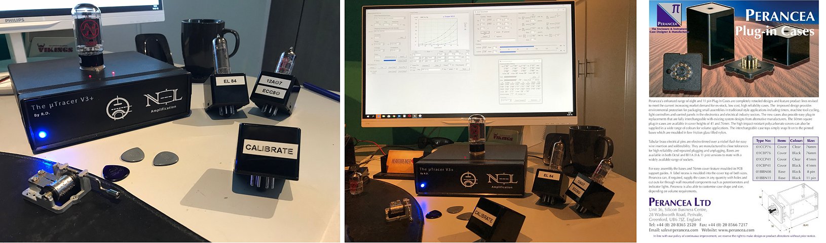
Dag Ronald,
Allereerst nog een gelukkig en gezond nieuwjaar gewenst voor jou en je familie he ...
Enfin na al het feestgedruis heb ik vorige week wat tijd vrijgemaakt voor de uTracer in mekaar te steken (fluitje van een cent met zo’n handleiding) en alvast de eerste lampen getest… Ik moet zeggen, ik ben helemaal omvergeblazen hoe goed de uTracer werkt, de mogelijkheden en het gebruiksgemak ervan zijn ongeëvenaard en voor die prijs... Ongelooflijk wat een krachtig meetinstrument in zo een compacte vorm. Wat een aanwinst voor onze shop!!! Ik ga hem deze week een mooie plek geven bij onze andere testers, maar ik ben zeker dat die andere niet veel meer gebruikt zullen worden behalve voor het voorverwarmen van de buizen misschien haha.. Het zal zeker niet bij eentje blijven want we zijn hier met zijn drieën die erom gaan vechten om hem te gebruiken.
Ik heb snel een filmpje (lage resolutie) en een fotootje toegevoegd van wat eerste testjes op mijnen bureau. Morgen gaat hij dus naar ons werkkot verhuizen en maak ik nog wel wat foto’s en een verhaaltje hoe hij hier de show gaat stelen.
Wat vind je van de minimalistische uitvoering die ik gemaakt heb? 1 Octal voet op de Tracer die alvast geschikt is voor alle gangbare 6L6 en EL34 types en hij doet voor de rest dienst als ‘receptable’ voor de adapters die ik bouw in een ‘Perancea plug-in case’, simpel he, je kan geen fouten meer maken zo. Ik maak voor alle lampen die hier gangbaar zijn even een adaptertje en klaar is Kees. Bovenop nog 2 ledjes, eentje als de heater aanstaat en eentje als de HV aanstaat tijdens het meten, de blauwe voorop is als de voeding aanstaat.
Enfin Ronald mede dankzij jouw geniale ontwerp heb ik nu de ultieme tool om onze eigen buizen gitaarversterker ontwerpen die we dit jaar willen uitbrengen nog beter op punt te stellen.
Alvast nog eens bedankt en tot binnenkort.
Groetjes,
Geert
PS: the adapters Geert uses are from Perancea in the UK
31st of December 2017, As a New Year’s Eve present Keith Barnes send me a few pictures of his beautiful uTracer creation!
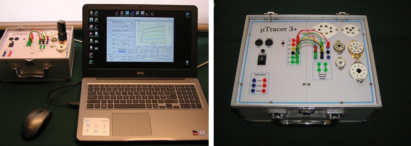
Dear Ronald and Marie-José
Just a brief note to let you know how pleased I am with the uTracer. The kit arrived early in October and, thanks to the excellent documentation, the board went together perfectly within a week. However, due to my limited workshop facilities, it has taken me until now to complete the full integration into a functional instrument. I decided to make it semi-portable by installing it in a small aluminium flight case (25x20x13cm), which I modified to have a removable lid. The uTracer and laptop PSU are mounted internally to the framework of the case, with a mains input socket and serial port at the rear of the left side. The 'front panel' is in two parts, with all connections to the uTracer on the left and valve bases on the right. This means that the right panel is electrically completely separate, so can easily be removed and replaced with a similar panel if other valve bases are required in the future. In the left panel I decided to provide access to the PSU and boost capacitor voltages in the calibration panel (lower left) and I also fitted a flashing red LED next to the anode and screen sockets to indicate high voltage present. My only regret is that I chose to use cheap plastic bodied 2mm sockets from China rather than the more expensive metal-bodied ones - big mistake.
Anyway, it is all working well and I am now learning how to use all the facilities provided. Many thanks for a very satisfying project!
Best wishes to you and the family for a happy and prosperous New Year.
Keith Barnes
27th of December 2017, Not really a testimonial but still nice mentioning an overview article in the November issue of Signal. (visit their site)
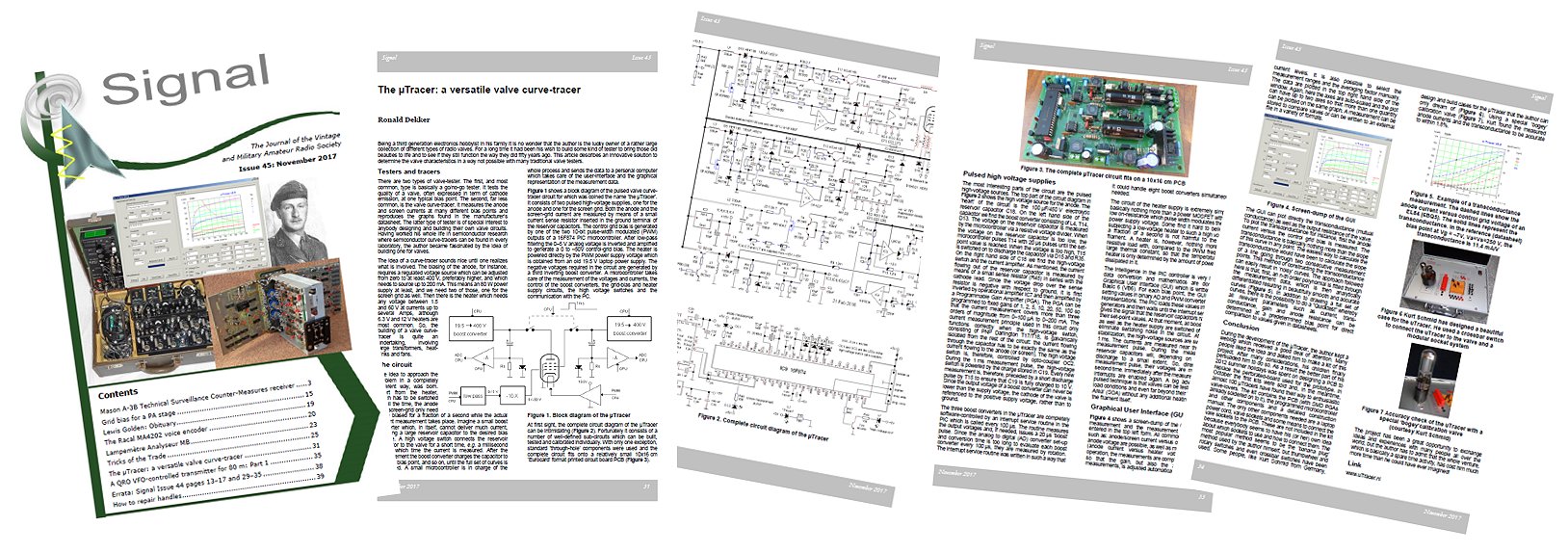
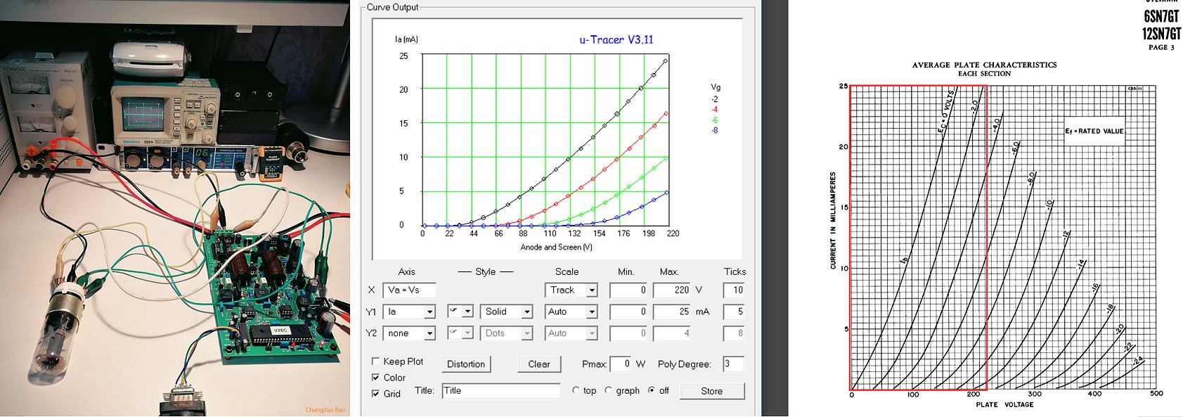
Dear Ronald & Marie,
I have received your reply and do your suggest, but my CP2102 dirve don't have "BM options".So I use another USB-RS232 cable.Finally it can work well! After finishing the assembly last night,I test a 6N8P tube which is a similar 6SN7 tube made in China. After watching someone else's design, I think it might be the best jump line to use a DB25 plug. So I will design a tube socket pcb next, it will also integrate the switchs,Bluetooth and LEDs. I'll also tell you the latest progress and keep in touch. Again, pay homage to the instrument that you have designed such an amazing device!
Regards.
ChangJun Bao
from Shanghai China
22nd of December 2017, Yoshihiro Uda from Japan sent me a few pictures of his uTracer. Visit also his website
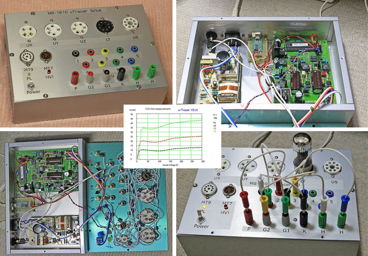
Dear Ronald,
Season's greetings!
I noticed that I missed to send you photos of my 3 plus-version uTracer completed in October, 2016.
Several additional photos and some notes can be found the link below: http://www7b.biglobe.ne.jp/~cpu_bach/ms1610_uTracer.html Sorry my Web page is written in Japanese.
Best regards.
Yoshihiro Uda, IEEE senior member.
17th of December 2014. Several uTracer owners showed their version of the uTracer on the annual NVHR day.
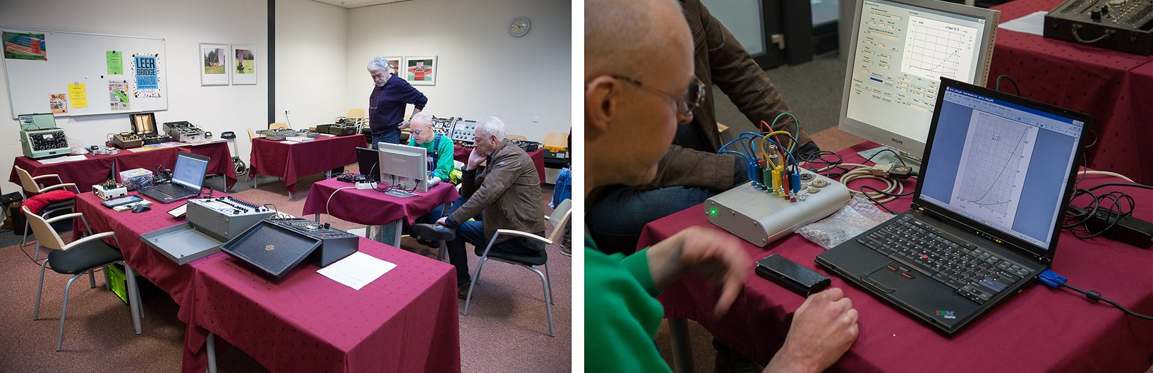
The “Dutch society for the history of Radio” NVHR unites people who are interested in, or collect vintage radio equipment. It regularly organizes gathering where vintage equipment is repaired or sold and bought. On the 17th of December 2017 during one of the meetings there was “a special” on tube testers. Several Dutch builders of the uTracer showed their embodiment while also a number of vintage tube testers were demonstrated. Unfortunately I was not able to attend due to a severe lumbago. Click here for a photo impression by Piet Blaas.
11th of December 2017, Holger’s uTracer is up and running and he has a few good tips for the construction manual!
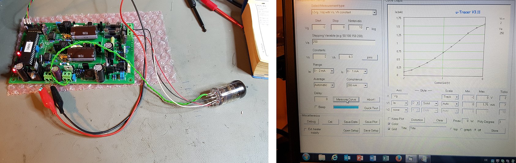
Hi Marie-José and Ronald,
The parcel arrived and the kit is already up and running. ? I am really, really impressed about the quality of the kit and especially the build instructions. I’ve never before seen such a detailed and next to perfect construction manual! Whenever a question came to my mind, it was already covered in the next sentence of the manual. Really great.
However, I still managed to make a mistake. I mixed the two 121kOhm resistors up with 12k1 resistors, which resulted in -4V instead of -40 Volts. However, quickly found and fixed. You may want to put a warning into the next revision of the manual.
There is just one question left. Maybe I missed it in the manual. There are two 2,2nF capacitors, which are not populated (C15/C20). Did I miss something? I found pictures of uTracers on the internet where these are populated. However, on the pictures in the manual, it is also not populated.
Attached are the pictures from my first test. Now I have to buy sockets and housing stuff….
Thanks and best regards from snowy Salzburg
Holger
17th of December 2017, Pentti from Finland gave me an update on his and Salasmaa’s utracer!
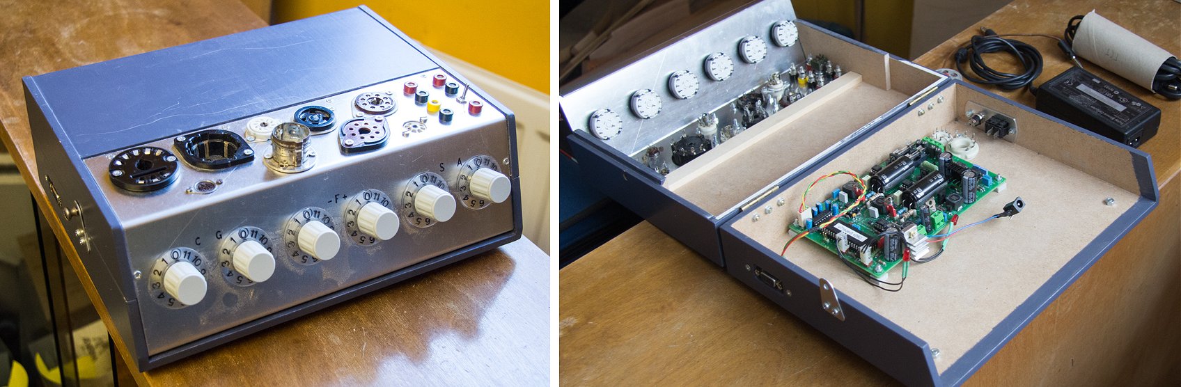
Dear Ronald
For quite a lot of years ago together with Lauri Salasmaa we ordered uTracer, and these two were the very first uTracers in Finland.
I finished the circuit, made the first measurement (a half of ECC8?), that resulted in curves seeming to be OK. Then I designed the box for these two instruments, which I even manufactured, and I put my print in it, but then my forces ended. I could not find power to go further. Salasmaa is now at the same situation. We have not got our instruments totally finished. I have the ferrites, I have the wires, but to solder all in their right places I have not had power to.
Now one of my RA-friends came to me to see the Racal RA 1772, which I have in my hamshack, and he was very interested in the uTracer. He has now studied the uTracer-pages, and maybe he shall build his own instrument, too.
I add some photos of my not-yet-finished uTracer. The other, built by Salasmaa, is similar, even the colour of the box is the same.
My best regards, and Merry Christmas to you and your family.
Pentti, OH3GQM
11th of December 2017, after a bit of problems with oscillations Paolo’s uTracer is working perfectly!
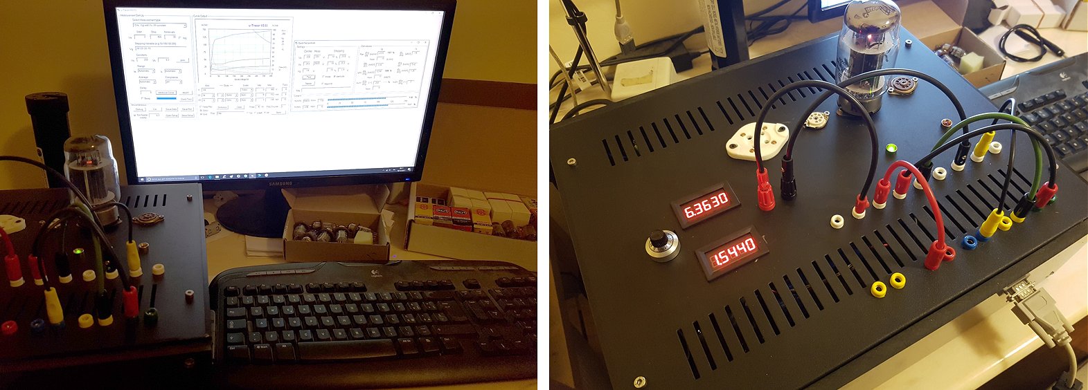
Dear Ronald,
I'm writing to tell you that finally my utracer is finished and working. Thank you so much for making this fantastic tool much more useful than a vintage tube tester. As you can see from the picture, I installed a separate power supply for filaments.
Best regards,
Paolo.
24th of November 2017, Jerry Long from China finished his uTracer!
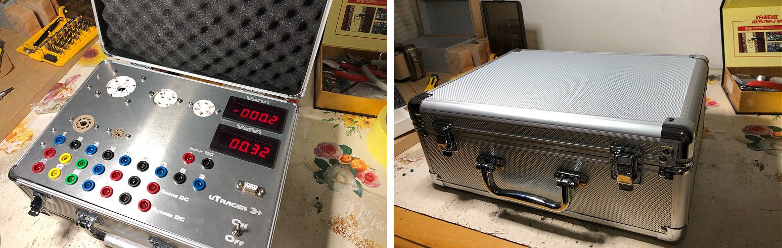
My uTracer has built up now. Thanks a lot
10th of November 2017, Gianni Franci Finished his uTracer and he is very happy with the result!
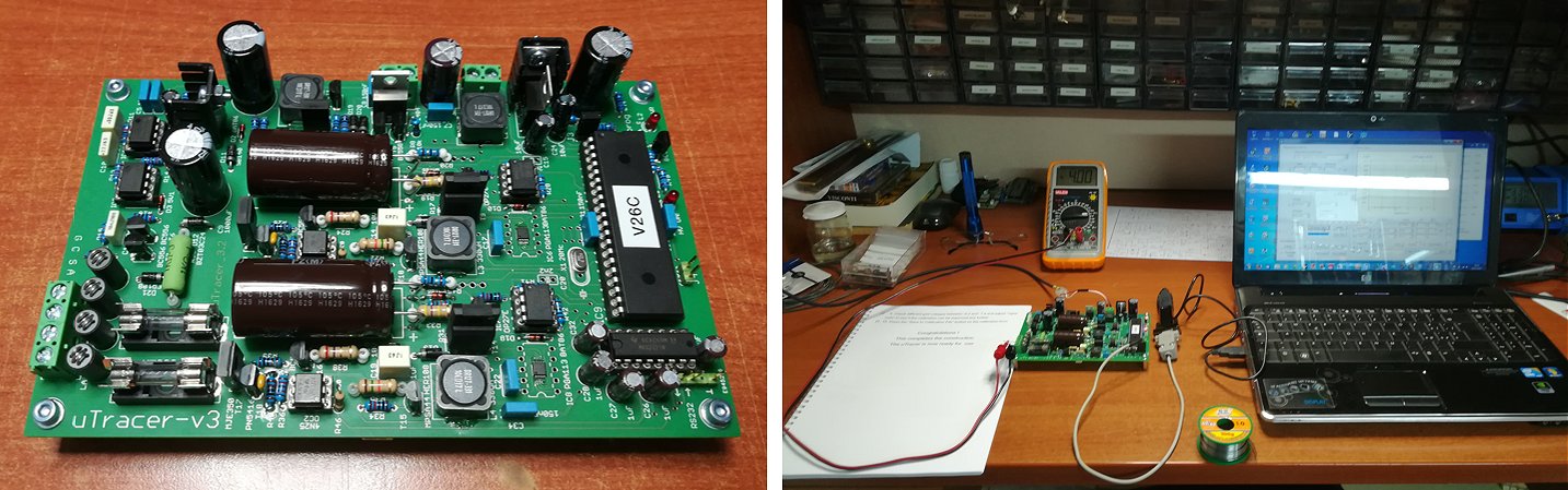
Hi Ronald,
uTracer 3+ succesfully assembled and perfectly working!!!:-)
A great project and a perfect kit (really idiot proof!... :-))
Next step: to choose an enclosure and put it in!!...:-)
Thank you so much!
Gianni.
2nd of November 2017, Gianni is ready to start the construction of his uTracer!
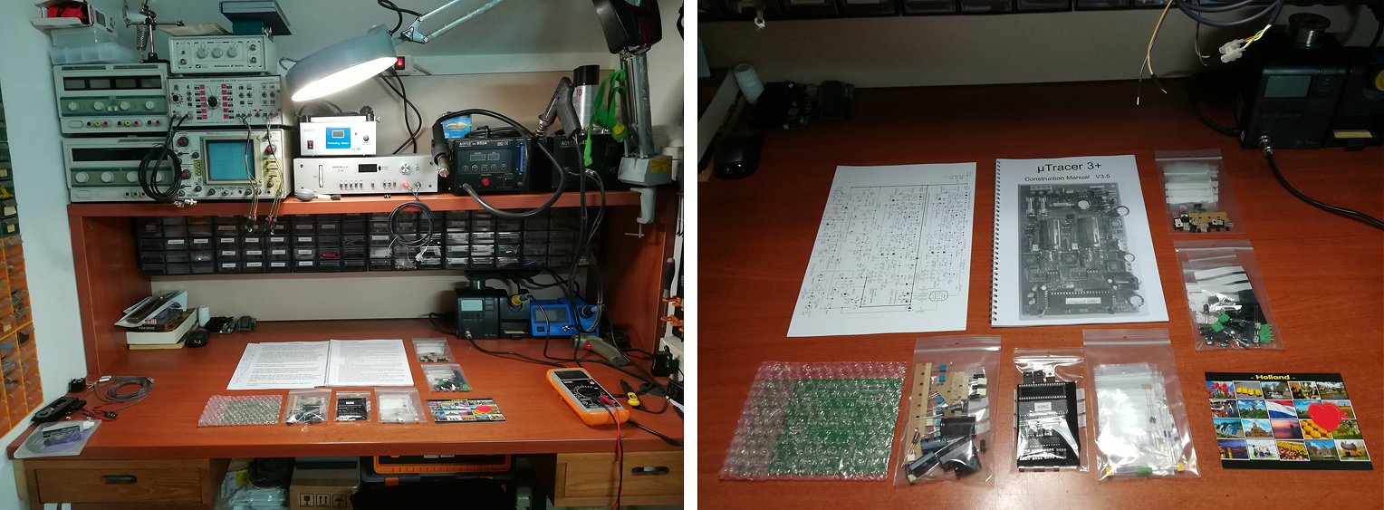
1st of November 2017, Valery is very pleased with his uTracer!
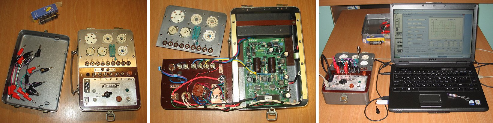
Hello Ronald!
I present the promised photos of my version of your beautiful device.
I used the case from an old analogue avometer and tried to keep the retro style.
For communication with the computer, the built-in USB and Bluetooth interfaces are used (Prolific PL-2303 and HC-06).
In addition to conventional tube sockets, DIP ZIF socket is installed for testing miniature tubes with flexible "legs". On one of the photos in this socket is tested a Russian miniature triode 6?6? (6S6B). Unfortunately, I photograph as badly as I write in English. Long live Google translator! :-))
Later I will make an additional replaceable plate with other tube sockets.
Thank you very much for your great work.
With best regards,
Valery.
15th of October 2017, Max Aitken reports another (beautiful) uTracer successfully completed!
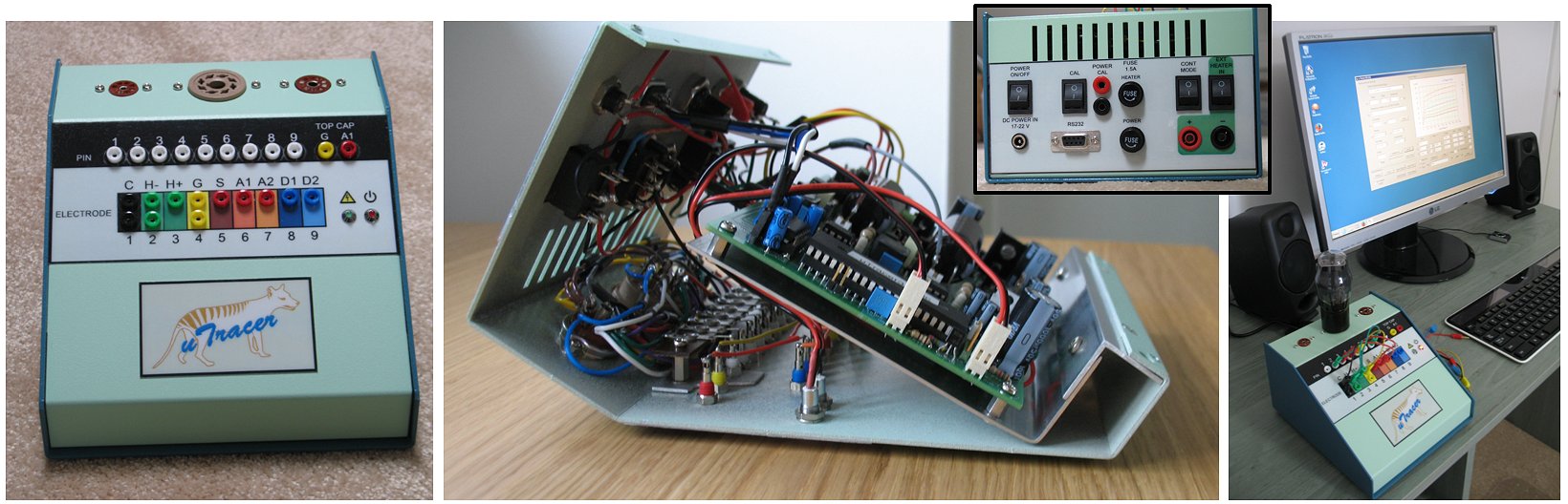
Hi Ronald and Marie-José,
Finally - here are some photos of my take on your brilliant concept.
I bought the kit when living in the UK, then moved to Tasmania for a while where the uTracer was assembled and tested. It was only when I moved back to the UK that the case was eventually completed. We're now in Seaford, not too far from Hastings, which you have visited. There was a considerable break for house renovations before I was allowed to construct my new workbench!
So it has taken a mere 3 years in all to complete the project but on the plus side I had plenty of time to decide on the layout I wanted. I would have liked to use a thumbwheel selector switch similar to a Avo VCM, which I'm used to, but I wasn't happy with the ones that were readily available so I decided on this layout of sockets. Although there is some duplication it does mean I can use the familiar Avo Data Manual settings and it works well for me.
I think Martin Manning's additional switches are a great idea and I've incorporated these on the back panel. They've already been really useful.
I included the image of Tasmania's sadly now extinct marsupial the Thylacine on the case to remind me of my uTracer's journey around the world during its construction.
Thanks again for designing the wonderful uTracer which is going to be extremely useful,
All the best
Max
2nd of October 2017, Mototaro Itano from Japan made a beautiful case for his uTracer! I want one too!!!
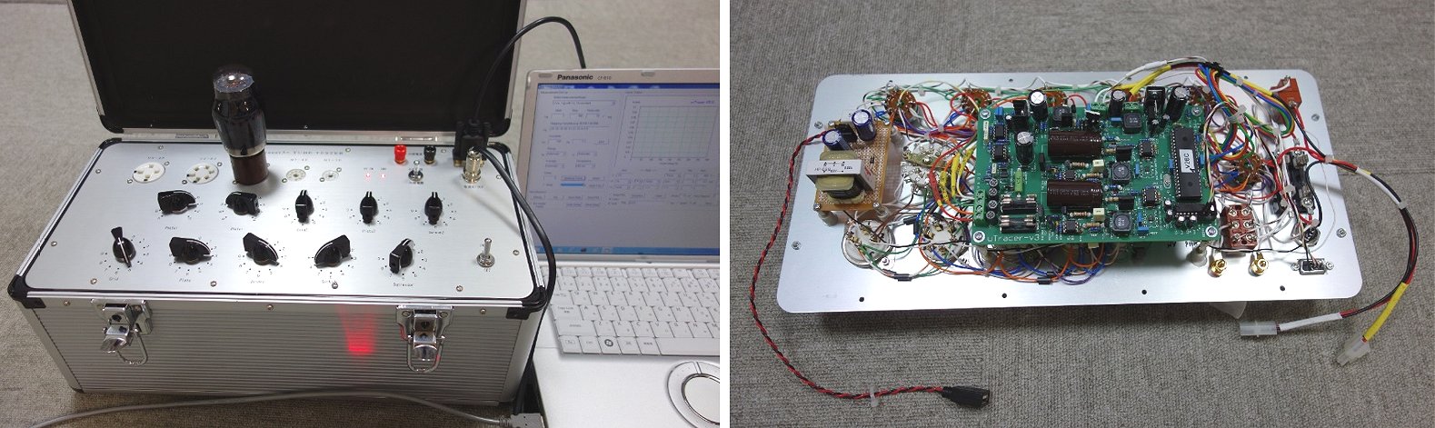
Dear Mr Ronald and Ms Marie-Jos
I am writing this email to inform you that uTracer 3 + kit has been
completed.
That could be made easily thanks to detailed production manual.
I copied the work of JF1KCM Mr Kaitsuka and made it.
Thanks to Mr. Kaitsuka's support and it was finished successfully so I send you the picture.
Thank you for offering a wonderful miniature Tube Curve Tracer.
Best regards
OSAKA JAPAN
Mototaro Itano
2nd of October 2017, Tomas Lannestedt’s uTracer is up and running!
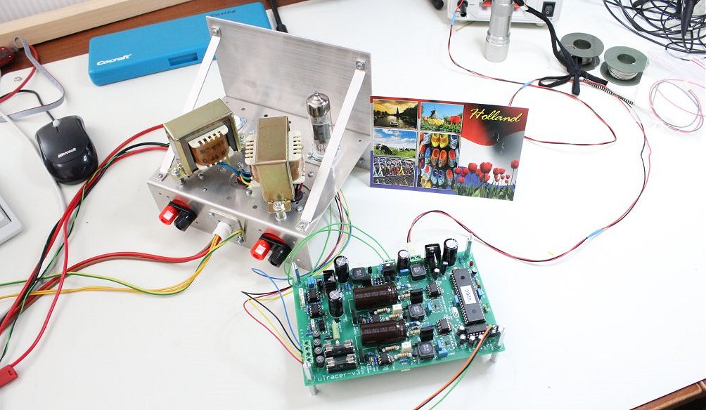
Marie-José and Ronald,
Last weekend I completed the build and test of the uTracer3+ and it
works :)
Here is a picture when I test the pentode in a ECL82
BR
/Tomas
21st of September 2017, José Colmena sent me a few pictures of his cased uTracer and a link to a Spanish forum discussing the construction!
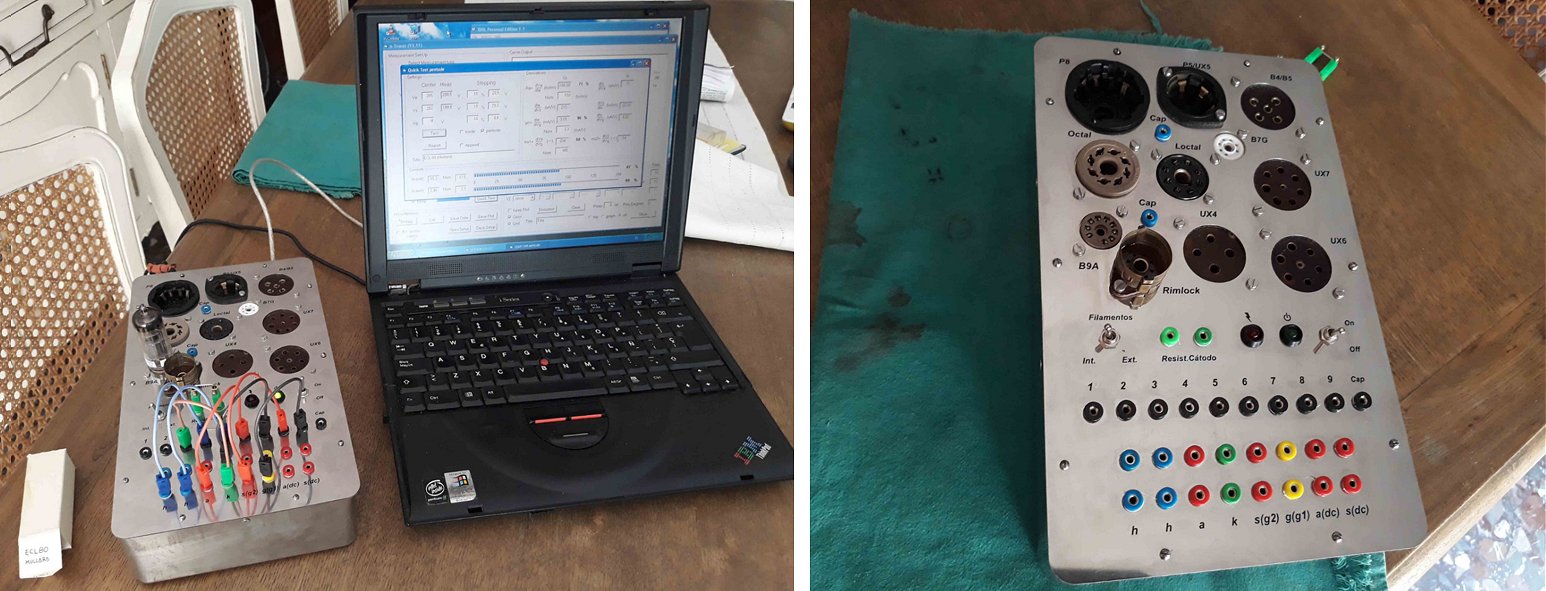
Hi Ronald.
After more than a year using uTracer I made the furniture for it.
I thank you for your efforts to ensure that there are so many happy people to use uTracer.
I send you some photos of my completed uTracer.
I also send you a link to a Spanish language forum where you can follow its construction.
A greeting.
José Colmena
Granada (Spain)
http://analogicalsound.esforos.com/el-utracer-3-de-ronald-dekker-t270
10th of September 2017, Edmond Verrijn Stuart reports his uTracer working.
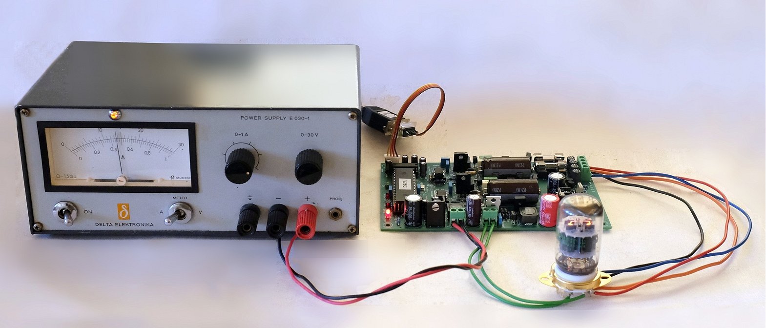
Hi Marie-José en Ronald,
De constructie van de uTracer ging van een leien dakje, niet in de
laatste plaats door de voortreffelijke handleiding.
En, niet geheel onbelangrijk, het werk! Zie foto's. Heb die ook gepost
op facebook, in een aparte audiogroep.
Dat leverde in een halve dag al 24 "likes" op.
Het wachten is nu op een geschikt kastje uit Hong Kong om alles in op te
bergen, tezamen met PSU, metertjes, buisvoeten en plugjes.
Als het zover is stuur ik wel weer wat foto's op.
Nogmaals mijn dank voor jullie belangrijke zo niet onmisbare bijdrage
aan de "buizengemeeschap".
Hartelijke groet,
Edmond.
PS: Ben zo vrij geweest drie elco's te vervangen door een korter
exemplaar (20mm) i.v.m. beperkte ruimte in de behuizing.
Vandaar die rode elco.
Het buisje is overigens een dubbel pentode compactron van GE.
3rd of August 2017, Mitch Markin Sent me a series of beautiful pictures from his uTracer. It was difficult to chose!
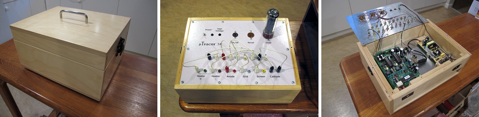
Hi Ronald,
I finally got the uTracer I ordered last October packaged up in a nice enclosure that I built using Baltic birch plywood and sheet aluminum.
The kit went together very well and worked the first time. The circuit board and parts are first rate and the construction manual is very detailed and easy to follow.
I downloaded the construction manual before I placed the order to become familiar with the uTracer and how it is built. It was nice to receive a proper printed and bound version of it with the kit. That's something you rarely see with kits these days.
The software works well on my Windows 10 laptop. There were no problems installing the software or communicating with the uTracer board. I ran it with the RS232 interface initially through an external USB adapter.
With the internal USB board I installed the uTracer just appears as a COM port when its power is turned on and everything works normally after that.
Excellent job with the design and kitting, Ronald. I'm sure my uTracer is going to be a very handy device on my electronics bench.
Mitch Markin
Canada
22nd of August 2017, Eric Kunz from Swiss traced an ancient 205D with his uTracer. Awesome table, awesome uTracer, awesome tube!
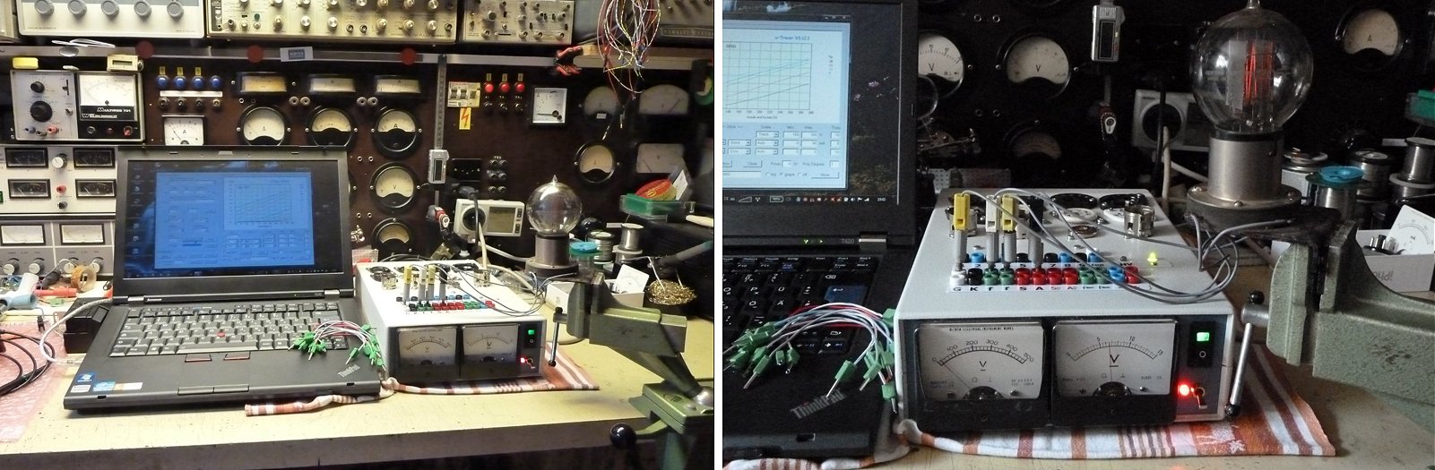
Guten Tag Ms Marie-José
Mein uTracer ist fertig und funktioniert einwandfrei auch bei ganz alten Röhren wie 205D von Western electric, siehe Anhang! Habe auch ein kleinspannungsnetzteil eingebaut für Heizspannungen unter 5 Volt. Für weitere Röhrensockel werde ich in einem separaten Gehäuse unterbringen.
Es ist ein super Gerät.!!!
Mit freundlichen Grüssen aus der Schweiz
Eric Kunz
6th of August 2017,Freddy Utsch’s uTracer is working and he sent be some pictures of a typical first “Beta test”!
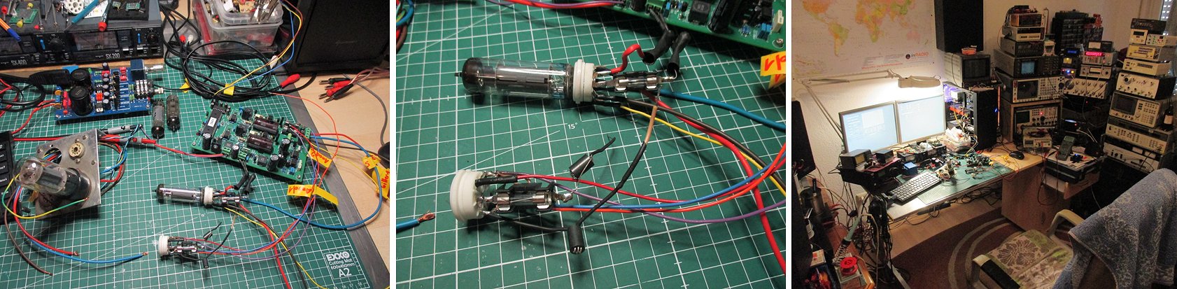
Hi Ronald.
After the little problem with the USB rs232 Converter(now I go directly
to RS232 on my Systemboard) it works really great. The documentation is
very, very good.
Perfect how to build explain. And very good documentation how to
calibrate the built circuit. This all can easily be done in a few
hours. Also the package with the parts is very good. No missing parts, just perfect. Very, very fair price for this big piece of work!
In the future I will build a little case, now I made quick and dirty noval and octal adapters to measure el84 pentode, ecc 83 85 88 double triode, and el34 6l6 6p3s.
Thank you from Germany Freddy Utsch
20th of July 2017, Andreas Neuffer’s uTracer and especially the tube adapters are a remarkable piece of craftsmanship!
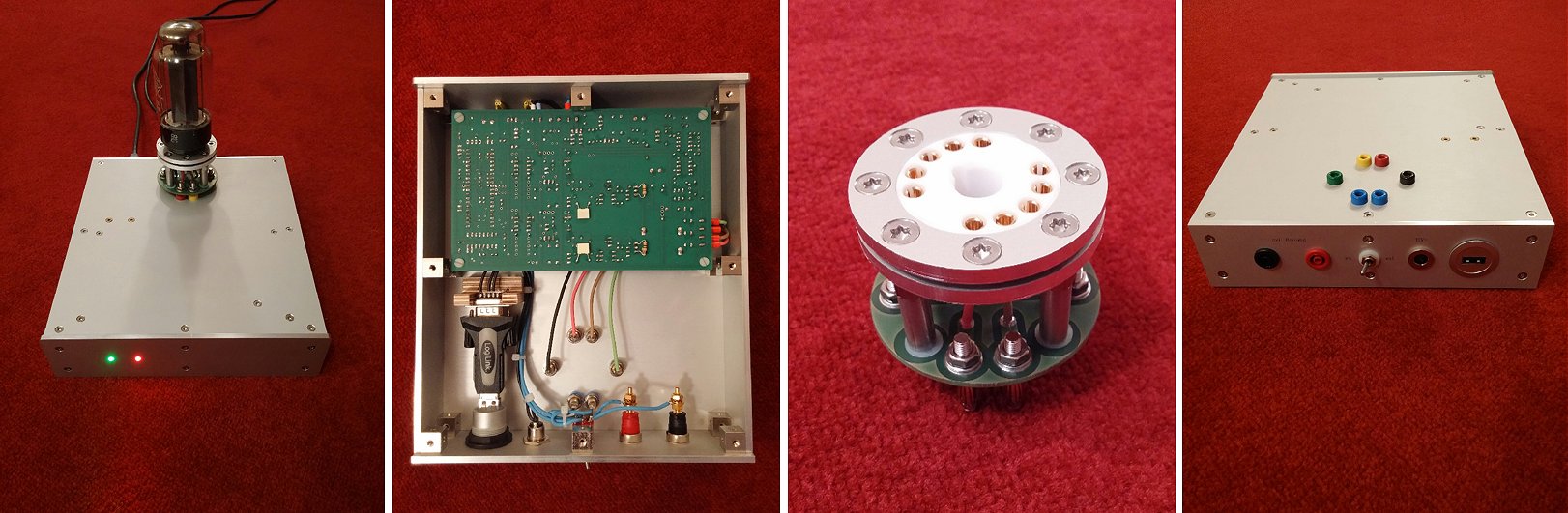
Dear Ronald,
Here is my implementation of the µtracer.
I built the electronics in a relatively small housing.
The connection to the PC is done via USB. The switch on the back is for changing the heating from internal to external.
On the front the power and the anode voltage LEDs are located.
For the different tube types I have built adapters to plug on the top in the banana connectors (you can see that for the EL156 tube).
I am very happy to have this nice measuring box and I hope you like it too.
Best regards
Andreas
9th of July 2017, António Gomes from Portugal did a first Beta test of his uTracer. Note how the pcb is supported by a wooden box for, how can it be otherwise ….. Port!
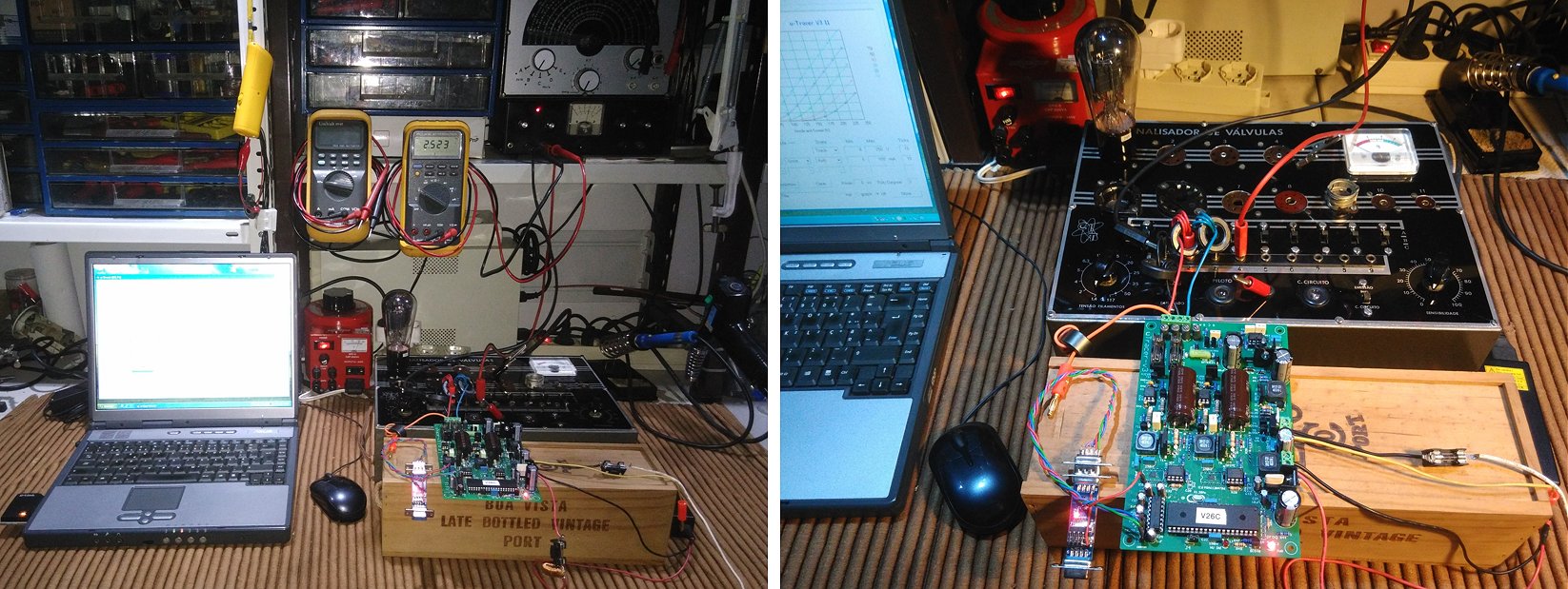
Dear Ronald and Marie-José,
Just finished the assembly of the uTracer (another in Potugal). The manual is excellent and the assembly went very smoothly, the hardest part was the software installation.
In the photos you can see the “beta” version, using an old tube tester as socket panel, Bluetooth connection and a “vintage” computer. This solution is very prone to oscillations, as i have watched when testing some EL84 and EL34. So, need to plan a box for it, add the sockets (with the suppression beads) and a few more tricks (shorts/leakage test, gas test, external heater, …).
I´ll report again as soon as i have the final version.
Thank you for this excellent piece of equipment.
Kind regards,
António Gomes
11th of July 2017, Peter Mach made a handsome compact uTracer and made a nice set of cards in power point to remember the wiring!
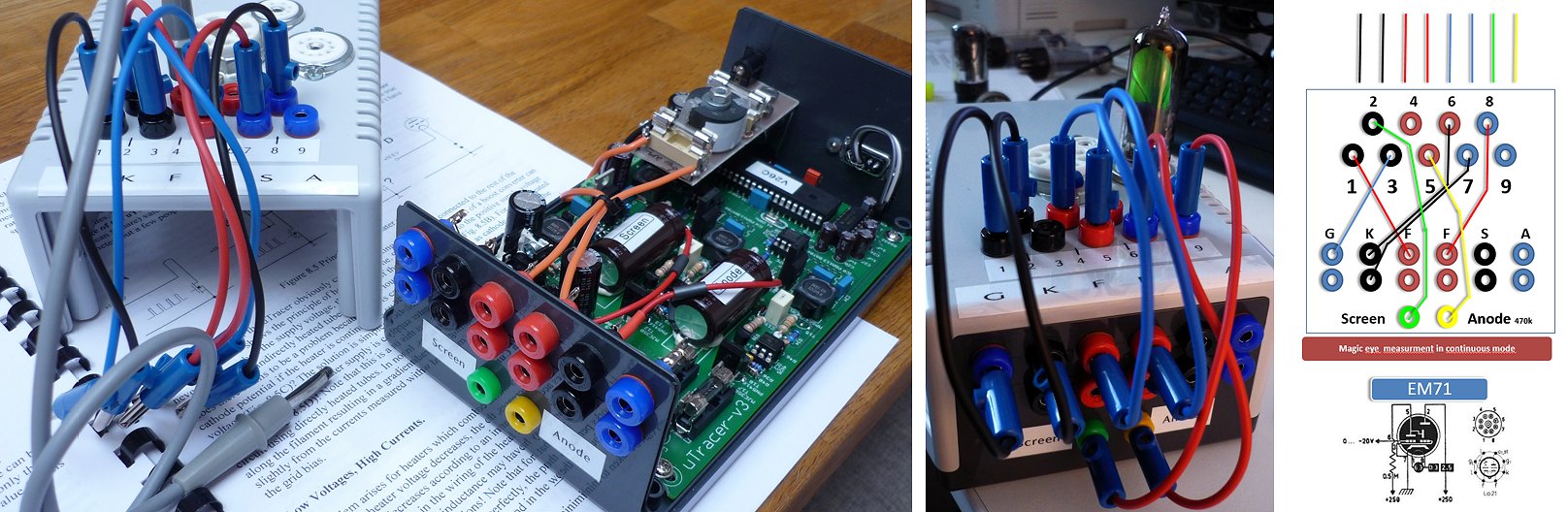
Hello Ronald,
everything works fine. The top of the box is removable avoiding permanent connection wires.
I wrote a ppt (click here) to remember my wiring..
Thanks a lot,
best regards,
Peter
11th of July 2017, Tsvetelin Simeonov integrated his uTracer in a very slim and stylish housing!
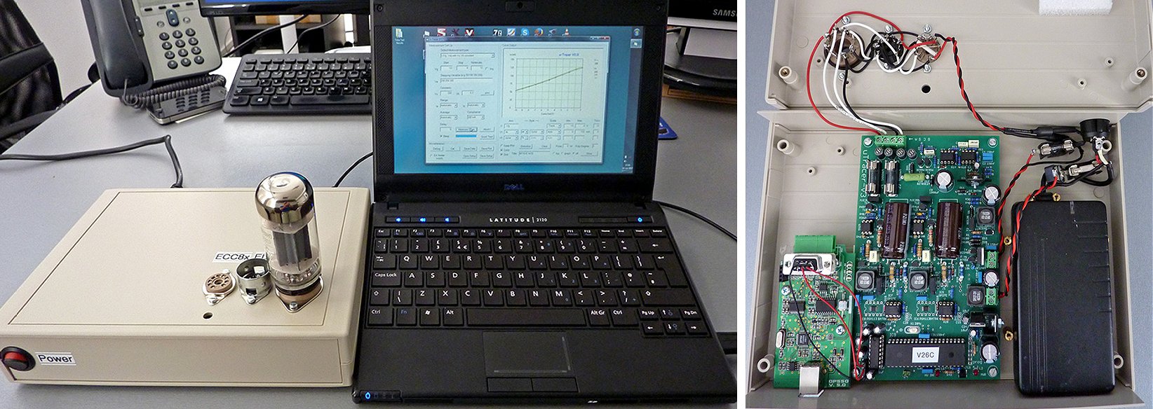
Hi, Ronald!
I'm writing you just to inform you that my kit is completed. Since your kind help (for the L2 bad solder) everything went smoothly and now the uTracer is working perfectly! I'm very happy with the result, it was a fun project and now it is a very powerful tool. Thank you for all your hard work, dedication and willing to help to the other tube fans all around the world. Best wishes to you and your family!
Here are a few pics of my device. It's not perfect and I have a few things to polish in the next days, but it's not bad at all and it's working fine! :)
Best regards,
Tsvetelin Simeonov
25th of June 2017, Ke-Fong Lin’s uTracer is working and he found a very nice way to mount the inductors!
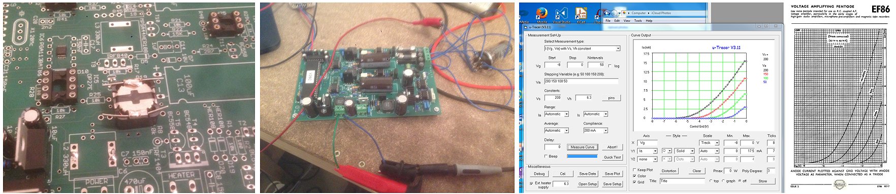
Hi Ronald,
Just to let you know that I completed the build successfully and the first test appears successful too.
For the 330uH inductors, I've used the cut leads from the resistors, see photo. That adds some mechanical strength, in addition to the soldering. I'm currently testing using a lab PSU. I need to go buy the 19V DC/DC supply, buy a box, and put everything inside. However, I was able to do a first simple test using an EF86 wired as triode. For this first test, I only wanted to check the measurement system, so I used an external (lab PSU) heater supply.
The measurement returns meaningful results. Tested tube is a NOS (at least it was sold on eBay as such) EF86, Haltron brand. Current measured is a bit lower at some place than data sheet curve, but the tube can be said to match specification.
Very nice work you've done with your uTracer. The construction manual makes building and testing along very easy. The kit is outstanding, the components are the best quality available.
After some more use and tests, I can forward you some more comments and may be suggestions.
Best regards,
6st of June 2017, Taka Kaitsuka turned the humble uTracer into a beautiful instrument!
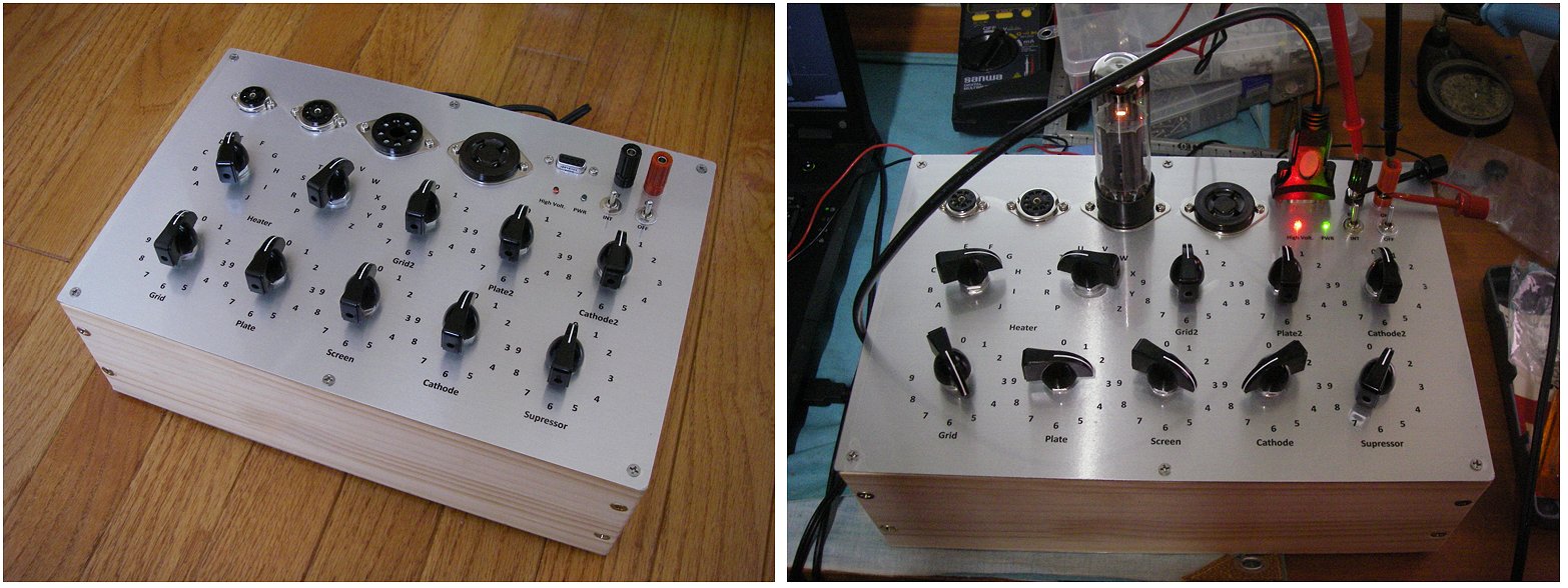
Hello Marie-José,
I have completed the all assembly and casing. I have attached some pictures that I took during the assembly.
Again, thank you very much for giving a chance to have a nice curve tracer for vacuum tubes.
Best regards,
Taka Kaitsuka
1st of June 2017, Heinz Huber is very happy with his beautiful uTracer!
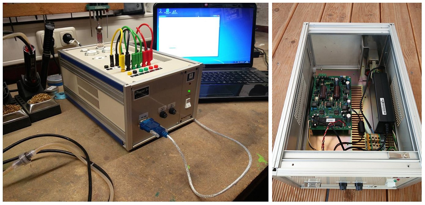
Hi Ronald an Marie-Jose,
Today I finished my µtracer.
Building was a real fun - thanks to your perfect instructions.
I took an old 19 inch housing which i chopped to its half width.
The rest is pretty much standard wiring.
Thank you for this fantastic project.
It`s really worth to build it. Low Price - High Quality - Perfect !
Best regards
Heinz Huber DG6MBZ
Germany
26th of May 2017, Morgan Jones, the author of several books on valve amplifiers, sent me a nice photo of his uTracer!
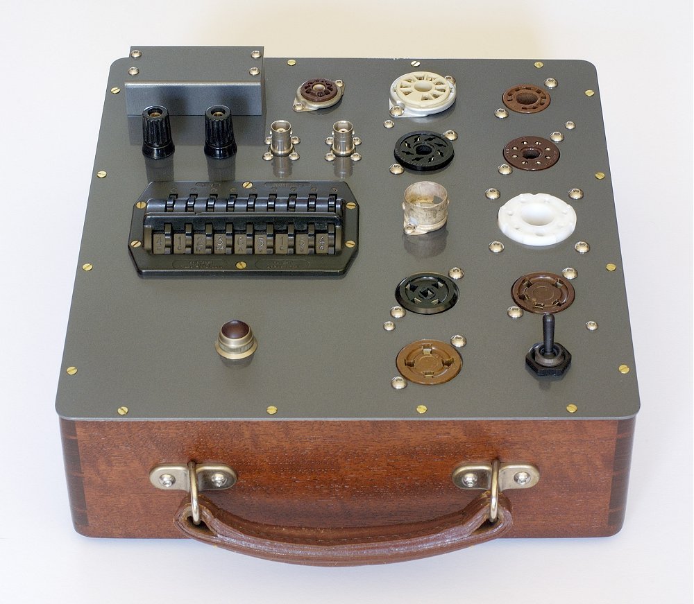
Having more curve tracers than oscilloscopes, I was wary of the µTracer3+, but quickly found that it was an excellent instrument, very thoughtfully designed, and any casing was worthy of similar care. I had a selector pin switch salvaged from a 1940s AVO valve tester, so that forced a “retro” look. A scrapped Tektronix oscilloscope donated the binding posts, a Telequipment oscilloscope the red warning light (now fitted with 10mm LED), and the valve sockets were NOS. The wooden case with leather handle was originally the lid from a laboratory-grade 5” mirror scale moving coil meter made by Ernest Turner, now hopelessly outclassed by any of my DMMs. I built everything on the panel, and the 9-way D-type and incoming 19V chassis plug created a problem because I wanted to hide these modern connectors, so I made a little assembly in the corner to hide them from casual view and allow their leads to come out horizontally.
Starting from front to back, the valve sockets are; American 4-pin (2A3), American 5-pin (807), British 4/5-pin, B7G (EF91, etc), Septar (13E1), International Octal (EL34, 6SN7, etc), Loctal (7N7), Noval (ECC88 etc), Magnoval (E55L), Novar (6CL3). Heaters can be selected to the µTracer3+ or to an external supply via the binding posts. The two BNCs will be for anode and g2 voltages, but adding an oscilloscope earth to computer earth at the moment would short an internal supply, so I need to opto-isolate the data connections before I make the BNCs live. The toggle switch at the front switches the instrument on/off.
Morgan also wrote a nice article on the uTracer in Linear Audio.
3rd of May 2017, Harald Naujok’s uTracer uses a clever homemade adaptor socket!
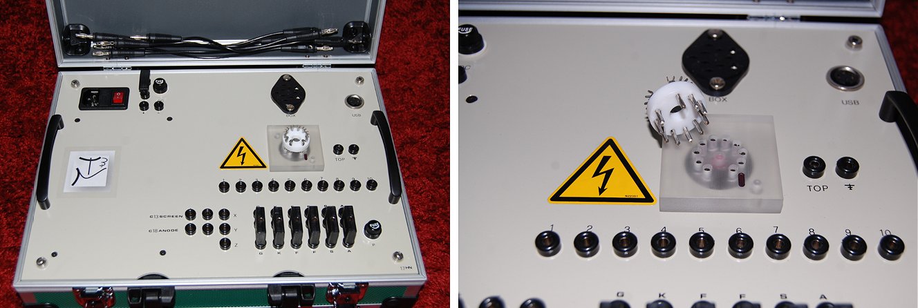
Hi Marie-Jose and Ronald.
The tracer works without any problems.
Very good construction.
The tracer works with the your USB adapter tip on Windows 10 excellent.
Thank you for this tool.
See pictures attached.
Everything was done in my workshop.
Also the special acryl tube socket with the HV LED inside.
Thank you for this u Tracer 3+
Best Regards.
Harald
22nd of April 2017, Shaun Merrigan went for a Heathkit look!
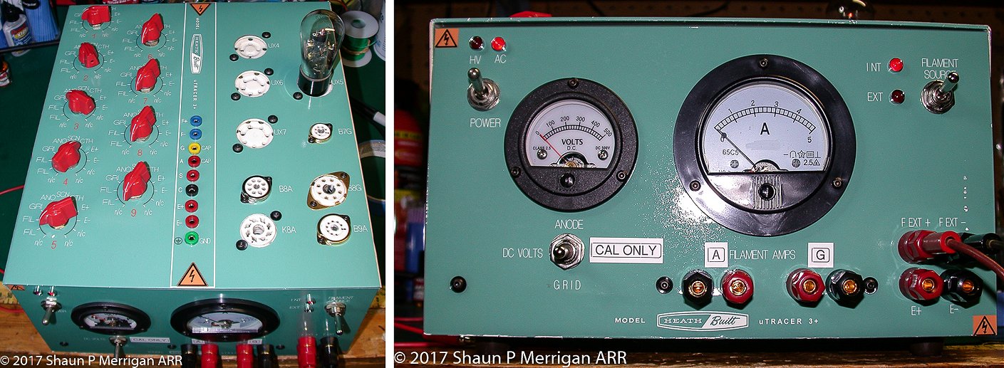
Ronald,
My uTracer is finally completed and working extremely well. Constructing and testing the actual circuit took far less time (thanks to your comprehensive manual) than fabricating the case and switching arrangement. I have added the following to the standard build:
- front panel access to the reservoir caps (also used for calibration the boost converters)
- Front panel switching in of two precision 10k resistors (10008 ohms each) for checking the current amplifier calibration
- External/Internal filament supply switching
- Large analog meter for external filament current monitoring
- AC and HV on LED indicators
- Heathkit themed enclosure and panels
- Big, beefy toggle switches for all front panel switching (fits with the Heathkit theme)
- Rotary switch selection of tube socket pins via military surplus ceramic rotary switches
- The capacitor modification that you and Martin showed (C10 and C11, LP filter caps)
Best Regards,
Shaun Merrigan
8th of April 2017, The uTracer from Paco from Casonavasolutions in Swiss is perfectly practical!
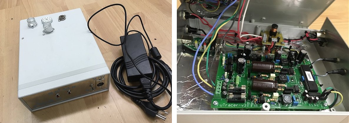
Dear Ronald
Last year, I bought one of your kits - finally, I had some spare time to work on it!
Here is mine - simple, no matrix - since I'm just need to test normal audio valves such as standard dual triodes and pentode and tetrode output valves (6V6, EL34, KT66, 6550 etc....) used in guitar amplifiers. I have two sockets for preamp tubes (one specially for use with an adaptor for odd ball tubes) , and two for power amp (octal and noval sockets) tubes.
Also integrated a USB/RS232-converter into the box.
Much thanks for your great project! I had a lot of fun building it.... :-)
all the best
Paco
27th of March 2017, Dominique Prost’s from Audiotronik reports his uTracer ready for use!
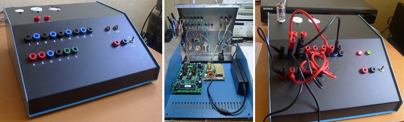
Hi Ronald, Hi Marie José
Utracer is finished, the tube tester started without problem after I built the kit, it is in the box and began to make his first measures...
Now I have to domesticate this very complete software.
Thank you for having designed this realization, I stay connected to your web site to be informed about some updates...
here is some pictures for testimonial
Bien Cordialement.
D.Prost
11th of February 2017, Jesper Karlsson made a thread about the construction of his uTracer on
a Swedish forum!
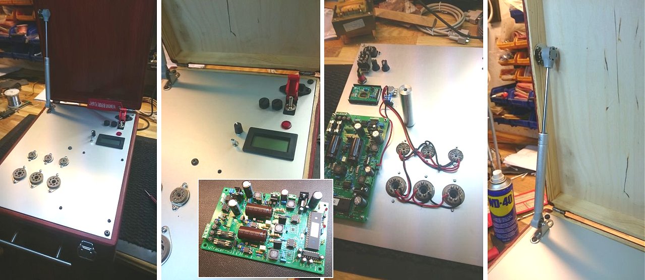
Hi there Ronald!
A while back you asked for build pics and thus..this mail.
http://ljudbojen.com/viewtopic.php?f=24&t=113469
I´ve made a thread as far as my build on a local forum,to us,where i describe in depth how the thing has been put together.
As you can see the actual box isn´t quite done and ready for service yet but...getting there.
Last thing i did last night before heading home was to tear the thing apart and hand that box its final layer of mahogany taint.
This will now be followed by some clear coat.
The sockets I’ve opted to install steady state into the faceplate are for the,to me,most common types tested like EL-34/6L6 et
al...6SL7...6SN7 aso...in turn EF-86...ECC-83 and EL-84.
For other tubes i´ve ordered so called saver sockets from Asia that i plan to take apart and simply repin to whatever is needed, down to even replacing sockets to be able to test EL-12 and what not down that path.
Sincerly; Jesper Karlsson
11th of February 2017, Carl Peter’s uTracer is finished and he is very pleased with it!
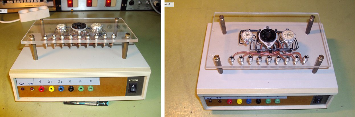
Hi again.
I have built the uTracer with no problems, it worked from the first time i switched it on. I think the construction manual and the test steps in the construction process is very good.
As You can see on my photos i have put the uTracer in a used box from another equipment, and I haven't done a lot for the finish. I was in a little hurry to get it working, and i don't think the finish will change in the future. As long as i works it is fine for me :-) I have made a plastic plate with the sockets i use at the moment, in the future I plan to make another plates with another sockets.
In the beginning I occasionally had some strange readings, I think it was due to some oscillations. When I put ferrite rings on the wires from the print to the banana plugs on the front the problem disappeared.
I am very satisfied with the uTracer, it works fine and is easy to use.
Kind regards
Carl Peter
11th of February 2017, After a few hiccups Mika Koskimäki’s uTracer is up and running!
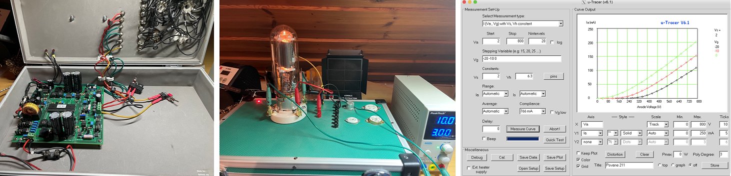
Hi!
Many thanks for the support with my utracer project.
Had some challenges but everything went great after you found my mixup with the op amps.
I managed to build a case for the tracer. Not so nice but practical.
Effectively I've been able to measure every tube in my collection. Very powerful tool indeed!.
Here is couple of pictures of my tracer :)
Thanks again,
Mika Koskimäki
27th of January 2017, Jean Huet finished his uTracer in record time and is very happy with the result. More pictures to come!
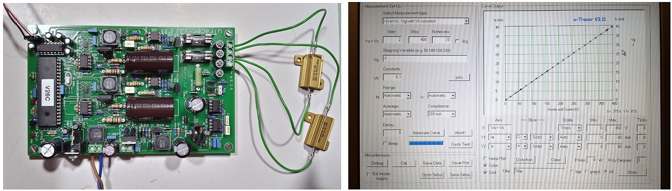
Dear Marie José, dear Ronald,
Construction finished, calibration done.
Everything went like a charm!
I will now clean up my mess, have a rest (I need it!) and continue
tomorrow with my first tests with a real tube and get experience with the µTracer during the coming days.
In the meantime, I will think about the final design of my tube tester.
As soon it is nicely packed, I will send you pictures (this will take more time!!!).
Many thanks for your kindness, and this great kit!
Kind regards.
Jean
25th of January 2017, Blaze Pawlak’s father made a fantastic project of his uTracer!
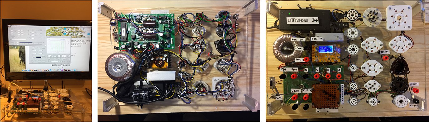
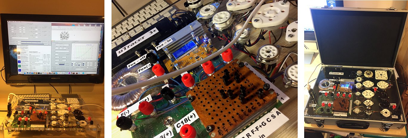
Hi Roland,
My dad finally assembled the kit I’ve ordered from you a couple of months ago (sometime in November, 2016) and I have to say that he can't find enough words to explain how much he admires your work and craft. The kit is just a brilliant piece of engineering both hardware and software wise. And the manual, oh the manual… I wish all products came with such detailed instructions that take one step by step through the assembly process and on top of that act as a check list. Big thumbs up for that!
Anyways, here it is. I’m attaching some pictures my dad took of the final product. It’s a custom case in old kick ass briefcase and the software is running in Wine on a Mac. Hardware got calibrated according to your instructions and we’re getting great results here. First few tubes that we tested revealed their true characteristics. Brilliant! Now I’m pretty sure my dad will be able to make better informed decisions about which tubes to use in his audiophile products. Everything to better quality and make recipients of his hardware even more satisfied.
You’re welcome to use the pictures on your site if you’d like. In case you’ve got any questions, don’t hesitate to drop me a line, I’ll be more than happy to get back to you :-)
Cheers and all the best Roland! Great work – that’s engineer talking to engineer.
Blaze
22nd of January 2017, Félix Menéndez and José Ramón report on their adventures with the uTracer!
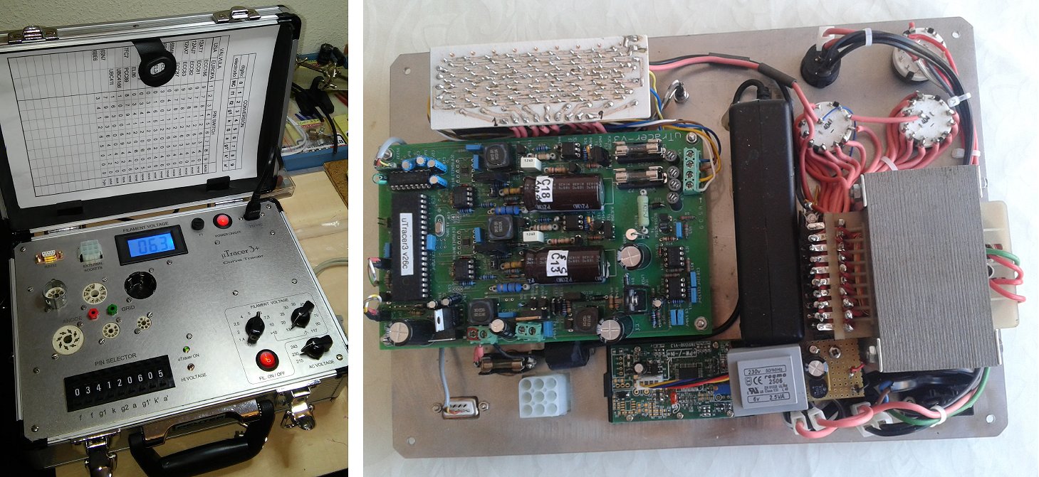
Muy buenos días, María-Jesús, Ronald!
Hope we are not too late in forwarding you our last uTracer version, bought autumn 2013!
Well, this is our third version. We started following your own build example. Then we developed a second, full of sockets. Soon we found that, for our particular usage of the tester (mainly in restoring, servicing vintage gear, as a hobby, of course, we are "boatanchors"), it was a bit boring the jumper-changing routine. So we ended up with this "cost-no-object" version with rotary thumb switches and only the most used tube sockets in our case, plus external heating (a filament transformer build for that application following a Metrix scale).
Everything in a professional looking metal carrying case, stainless steel front panel and laser text engravings.
First problem after the front panel was cut and engraved: we maintained the "electrode-selects-pin" approach of the jumper selection mode. But this approach, with rotary switches, enables you to make a nice short by mistake in the filament circuit, for example... No good practice...
We had to reverse our selection mode to "pin-selects-electrode" (Metrix style). So, the lettering is no more valid... a pity.
No big deal, though. Anyway, you had to resort to the switch numbering scheme in the booklet we are building for each tube class.
Enclosed a couple of photographs of the machine.
And congratulations for a very useful test equipment!
Kind regards,
José Ramón and Félix
9th of January 2017, Mikhail Stolpner’s uTracer is in “Philips Blue” !
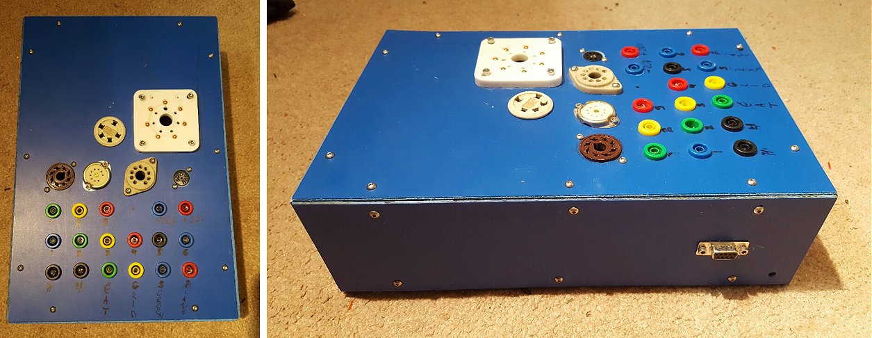
Hi Ronald,
I am super excited to hear that you keep working on improving the uTracer. It's a very helpful tool.
Attached are a couple of images of my build. I did not go for a look and it's a super basic build. Please, let me know if you want photos of the inside, happy to take them.
The most significant limitation for me is Vg. I would like to measure tubes like 6S33S. I would need to go between 30V and at least 100V with Vg. Do you think I can include a floating voltage source of 30-50V between the greed the uTraces?
Increasing a max Ia to about 300mA or even 500mA would be very helpful too.
Thank you very much!
Mikhail
7th of January 2017, Ebert Warmerdam turned his uTracer into a piece of art!
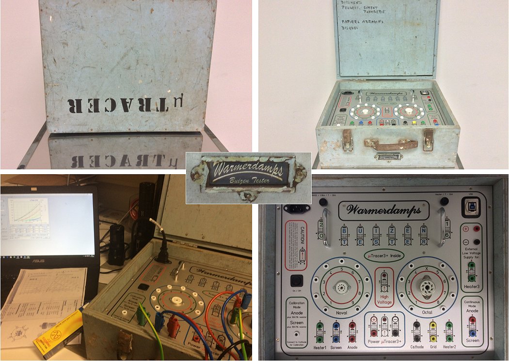
Hello Marie-José & Ronald,
Way back in 2014 I purchased your uTracer kit. As a guitar player I wanted to understand my amplifier more with the kit and hoped it could help me bring down repair time because every time I brought my amp for repair it was gone for a while and always came back with the remark that the cause of the problem had been a bad tube.
Kind regards,
Ebert Warmerdam
I am a musician, audio engineer and tube amp designer, and was delighted when I discovered that you had created the uTracer. I had previously been using a TV-7/DU and Hickok 739A, but found them, and the prototypes I made, very time consuming and limited for characterizing tubes, and testing my designs.
Your construction manual was very easy to follow, and I was able to get my uTracer built, working, and calibrated in one day. It took another few days to complete the case and wiring. The uTracer is a welcome addition to my workshop.
I am using your software on Windows XP 64bit, running in a VBox virtual machine on my MacBook Pro 17” running Yosemite OS. After a bit of fiddling to get the drivers in the proper places in windows, everything worked a charm.
I have also enclosed a photo of my latest amp build, a 50 watt/channel hifi amplifier using 6SN7s and KT88s that I call the PSW-100. Ive also enclosed a photo of my laboratory. . . both of which are highly improved by your efforts.
Thanks for creating such a fast and comprehensive tool to aid in my work and play. Over 800 of my friends have been avidly following my progress on Facebook as I have pushed the project forward to each stage of completion.
Best,
In pictures first run of my uTracer
Thank you
best regards
Dear Ronald,
I have studied electronics during my studies between 1981 and 1988, and then I left that world for computers. I'm now back in tube-audio so I needed some tools, including your fantastic tracer. I'm sailing during the spring-summer-autumn, this is why getting my uTracer in its box took almost one year. As I was interrupted by having to race 10 regattas in 2016, I needed two winters to build the tracer, in fact :-)
I attached two pics of the uTracer in its box (Hammond 1456KK4BKBU from Mouser). I used the USB-to-RS232 converter with an USB socket on the left of the box (not visible on the pics). I'm mostly interested in audio tubes that dictated my selection of sockets. I followed your excellent guide and here I am, first measurement of a very old ECC82 I had in basement. Now I need to dig out my books and archives and better understand how tubes work so I can understand what these nice curves means :-)
So your stats can be updated with one new uTracer in Switzerland :-) I wish you and your family a great year 2017, and thanks again for your work!
Charles
Hi Ronald and Marie-José
I just want to let you know that I completed my uTracer (well almost) and had no problems assembling it thanks to your excellent construction manual. Such high standard.
I opted for a compact version which will fit in a 3ru 19" rack. Only two Valve sockets installed but have allowed for an adapter to be fitted with different sockets when needed.
Working now through the manual to familiarize myself with the many options.
Thanks
Hi Ronald and Marie-Jose,
A photo of my uTracer3+ up and running, no hitches, thank to your well organized assembly manual. Building was a real treat, using even more so.
Thanks again for making this jewel possible!
Hi Ronald and family,
First off all thank you for all the effort you put into this great project.
Hi Ronald,
Sorry if I didn't write before, but unfortunately I don't speak English, so I always have to ask somebody's help.
Regards
Hi Marie Jose and Ronald…
As you already know I have bought several months ago uTracer kit that has been delivered safely to Croatia…
After occasional work finely a friend of mine, mr. Zdravko Kristic and me, managed to get things done.
uTracer is working perfectly from the very start and without any problems.
It is fitted in wooden modified box from local Bauhaus store, which give a vintage look to the device.
Now we have to learn how to unleash full potential of this useful tool but this is another story.
I am sending you some photos of our uTracer.
Wishing you all the best I am sending you warm wishes from town of Rijeka, Croatia.
Mladen Knezevic & Zdravko Kristic
Dear Ronald.
I completed uTracer assembly several months ago and I'm happily using it. It seems working well.
I did not write you yet because I would like to complete it with some look improvements. Unfortunatelly I have no time for these tasks, so I think that my uTracer will look as photos all its life long...I just need octal and noval bases at the moment because I work with guitar amps and they only use few kinds of valves.
In one of the pictures you will see that your nice postcard from Holland has a special place in my lab!
I hope for you the best. You really do so much for our community!
Ciao
Gabriele Carnevali
Fabriano (AN)
Italy
Read more about this beautiful project on: EEVblog Electronics Community Forum
Dear Ronald,
I thought I would let you know your uTracer helped me repair an old Tek 545 to full working order, it found 4 of the 100 or so tubes were not working.
Many thanks
Hi Ronald,
I successfully completed my uTracer in April this year. It took me quite some time to find the right cabinet for it. Finally I decided to use an old wooden filing box which just fitted the size of the uTracer PCB. It was a bit tricky to find a layout so that the socket wiring, plugs and the big old switch on the front panel did not intersect with the big electrolytic capacitors and other components of the uTracer.
Thanks,
Hello Marie-Jose,
Some weeks ago but the uTracer is now running.
Thank you for this great kit with a magnified description. You have done e really got job for a least a fair price for as tube-maniac’s.
Kind regards
Robert Waldow
Dear Marie-José.
uTracer was put in a box of My holdings.
Michikazu
Dear Marie-José and Ronald,
I finished my utracer a long time ago, and finally managed to make some (bad) pictures! I am very happy with it, I couldn’t do half of my projects without it!
I put the unit in a plastic container, with a second container on top to hold all the wires, power adapter, USB to RS232.
For my amplifier projects I use a lot of Phoenix PCB terminals, which I slightly modify as you can see in this pictures. That way my amplifiers are mostly “screwed together” (here are some pictures http://www.diyaudio.com/forums/tubes-valves/256577-transconductance-amplifier-headphones.html).
So I just use these tube sockets to test my valves, connecting them with the alligator clips to the utracer.
Feel free to post this on your website!
Erik
Dear Marie-José, Ronald,
last Weekend I finished my µTracer and measured the first Tube (an old EL 84). I am very pleased with the result!
As I have a small carpentry in my house, I decided to build an old fashioned Plywood case (like Funke and Neuberger). The chassis was built of a 4mm Aluminum plate, completely drilled and painted in my workshop. I opted for linear regulated power suplies for both, the µTracer and the heating. (Sorry, but I am old fashioned when it comes to power supplies, because I build tube amps for hifi). The heating supply can deliver up 12,6V @ 4A, higher values will be heated with my "big"
external power supplies.
I would like to thank you both for this outstanding kit! The documentation is a fun to work with. Everything worked fine and the software (GUI) is very intuitive.
best wishes, groetjes
Guido Lindges
I finished my uTracer. The building instructions were great and user friendly. Everything worked without any problem.
I added the 330uH coil, the ferrite beads and the fuses. As my dedicated laptop PSU was heating quite a lot (less than the idle LM337), I didn't put it inside the enclosure. I even re-used its ferrite bead. I bought a sort of mini-banana plugs that could be plugged together, so it was easier&cheaper. I used my PCB prototyping CNC to mill a grey covered black plastic-material, and then taped it on the enclosure.
Perhaps you remember that I design ultra-linear (UL) guitar amplifiers. Those contain the smallest amount of component possible. It's cheaper, so I could afford more robust components for the same price. I only design with the following tubes: ECC83 (9€) and EL34 (12.5€). They are cheap and sound great. 1xECC83+2xEL34 is enough to have >30W speaker output in UL PP. I put only the 8 and 9 pins sockets, because other-sockets tubes are too weak or too expensive to fit my designs.
Here are some graphs of a test EL84 and its resulting spice model. The Ia=UL(Ua,k) and Ia=UL(Ua,Ug) curves are helping the designer to quickly determine the best bias point for the UL operation. The Ia=UL(Ua,k) could be produced using the "Keep Plot" feature. Being able to have accurate spice model of my tubes in a quick&easy way is a big improvement for my designs.
Thanks for everything!
Hey Ronald,
Just thought I would send you some photos of my completed u tracer. Nothing fancy about the build, will be mainly using if for guitar amp tubes. Anyway. All went together pretty well. Had a few issues that I rectified and it does well. The external heater supply is a good addition. I measured the heater voltage with a true RMS meter and was measuring 5.4 volts for the heaters since it is a pulse current source I knew it would be difficult to set an accurate value so using the external heater circuit helps out with it. Anyway I'll attach a few pictures and maybe someday I'll make a nicer chassis for it someday.
10th of August 2016, Jan and Kryštof Soldán turned their uTracer into a very nice and compact instrument. Their whole instrument collection is pretty impressive by the way!
Dear Ronald and Marie-José.
I would like to inform you, that another uTracer was born in Czech Republic.
Jan
Hi Ronald,
First of all my congratulations for this fantastic engineering project !
I started to build the uTracer in December 2013 and it was working around March 2014.
I decided to buy the programmed PIC processor and to assemble the circuit on perfboard step by step because I have a large stock of components. The “difficult” parts were obtained from the free samples service of TI.
It was quite an experience and a challenge to start from scratch and complete it on perfboard – more driven by nostalgic feelings to assemble a project in this way after many years. However, after all, I would recommend the complete kit …
The uTracer works perfect and is mainly used to test tubes for my old radio’s. Up till now I have not upgraded to the 400 V version, 300 V is enough for the tubes I work with.
I also added the Bluetooth interface described by Mark in the Google group (Serial Module HC-06-D RS232/ TTL with EDR) which works perfect.
With a switch I can choose between the standard RS232 interface or the BT.
Kind Regards,
Filip Van Kenhove
Dear Roland,
It was a while ago I bought the uTracer kit from you!
Wish you and your family, a really nice holiday!
Best regards
Bo Johansson
Sweden
Hi Ron,
I'm exceptionally pleased with uTracer. I put the board inside a laser cut and engraved acrylic sandwich. I put the fuses and additional inductors on a homemade PCB inside the sandwich. I just plug a valve base in that hangs on banana plugs. I intend to mount the bases on their own acrylic sandwich but I've not done that yet. The acrylic master is enclosed as a dxf file (the spare space is filled up with components to make a B14G base). All very quick and simple but safer than playing with a bare board.
I suppose you can say I'm "experienced" in electronics and had no problem with assembly, testing or calibration. At the time I built your kit up I was developing my own kit for an Arduino Due base CRT clock. I learned a lot from your packaging method, manual design and style.
On another, CRT related, matter I am just building a CRT tester capable of testing CRTs that require up to 4kV to operate (and an extension board to 10kV). I was going to post a link on your forum to the webpage where I will give details of the design and kit that should be available. So not a competitor to your utracer and specifically for CRTs. Is this ok with you?
Our holiday this year was two weeks walking in the south of Spain and then two weeks with our feet up in a letting cottage near Bergerac, France.
Cheers Grahame
Hi, Ronald.
Wanted just thank you for your great engineering piece of work. The uTracer is every EURO worth I spent.
Kind regards
Sven Stalbovs
Hi Ronald,
Attached are some photos of the utracer I built. I plan to mount a couple volt-meters on the front panel. When I built it I had one goal in mind: Building the smallest utracer that can take as many sockets as possible. I am going to write an article about this cool kit and put it on my blog. Thanks for all the great works.
Regards,
View the website of Chris
Hi Ronald,
now I have it done to change the COM port number to 2 and it’s all at best.
Have you and your wife a nice weekend and best regards,
Detlef
Greeting from Pennsylvania!
The uTracer arrived safely yesterday and I verified the 12.1k resistors are in fact 121k resistors. I will proceed to build with that in mind and not place the incorrect resistors. I look forward to completing the build and putting the uTracer to good use. I will send pictures of the build as I progress and of the completed project. I plan on making my finished uTracer look like an antique 1930's Leeds and Northrup type design made with a wood frame and black panels.
Here is a picture of the assembly area.
All the Best,
Hello Ronald and Marie-José!
Boy was it fun to build the uTracer! Excellent documentation and step-by-step construction and test/calibration guidelines made it a very straight forward process. After checking the connections and recalibrating the I(a) and I(s) with a 1% spec resistor, all is working beautifully and the fun can begin.
In true spirit I did not buy a clean case, but opted for the time consuming trials of making a box using some leftover materials. I selected only the 8-pin octal and 9-pin miniature bases for now, for the testing of instrument and audio amplifier tubes such as 12AX/T/U7 series, 5687, and power tubes such as 6L6, 6550, KT-88 etc. There is some space for accommodating another socket should the need arise.
The actual board is securely mounted using brass machine screws and threaded nylon spacers with brass thumb nuts. It is easily removable if needed. I opted for adding a combination of chokes totaling around 340uH, and mounting RFI beads for the heater and fuses on a terminal strip inside the box wall (The RFI beads are underneath the terminal strip and don’t show on the picture) . To save space and keep the heat out, I indeed found an external old laptop supply that works beautifully, I just added a switch and jack. A vent hole to reduce heat buildup inside was added just in case. Incidentally it allows me to see the LEDs inside, an added bonus. At some point the leads will be properly sized, but first it is time to play!
Already I was able to detect issues with some new tubes that were installed to replace supposedly bad tubes in a bass amplifier. The 5-piece new name brand pre-amp tube complement included 2 bad tubes! Then, a new four piece matched pair of name brand 6L6 power tubes included one shorted unit. I found that in many cases, new tubes that are being sold by retailers are not tested before shipping. And, not every vendor is good about returns as they cannot verify a claim of a bad tube. Also, not all instrument amplifier technicians have a tube tester, often recommending replacing all tubes.
So I am very pleased with my new measuring instrument and in retrospect question how I could have done without for so long!
Hartelijke groeten uit California!
Harald Grabowsky
Hi Ronald!
I'd like to report about success in assembling my uTracer v4 "from scratch"... It passed all tests and calibration procedures (well described in your great manual). So, thank you very much for your great project!
Herewith I'd like to send some pictures as a "report".
Of course, the soldering of PGA113 was a nightmare...
The final pictures of pcb are also attached (at the moment, I still didn't remove the rests of soldering flux).
And of course, thank you once again for your nice project!!
With best regards,
Hallo Ronald en Marie-José,
Het project is voltooid. Het is misschien de meest fraaie behuizing, maar ik had deze nog.
Met vriendelijke groet,
Kit has been completed.
Please check attached picture, it’s working very well
Thank you.
Hi Ronald and Marie-José,
I’ve just completed construction of my uTracer and am very pleased with how it’s turned out. Your construction manual was really clear to follow and the uTracer worked OK the first time I used it. Attached are some photos.
I mounted the uTracer in a spare aluminium-covered case I had and fitted the RS232 to USB adapter inside the case. I also added an internal auxiliary heater power supply powered from a second laptop power supply which I set up to provide switched voltages of 2.5V, 5V, 6.3V and 12.6V. This also enables me to gradually bring the heaters up to their required voltage when using the auxiliary power supply. I also added the ability to connect an external heater power supply for tubes with high heater current consumption.
There is quite of lot of heat generated inside the case so I added dual 40mm fans to the front panel, one fan to suck air into the case and one to extract the warm air out.
I test mostly audio tubes so hardwired a set of sockets for the most common audio tubes I need to measure and added a second set of sockets that I connect using jumper cables. I also added a life test switch that drops the heater voltages by 10% by switching in extra resistors into the internal auxiliary heater supply circuit.
Thanks for producing such a great kit and also thank you to all the other uTracer constructors for the ideas I got from their photos on your website.
Kind regards
Paul Newman
ps: Paul wrote a description of the auxiliary heater supply he built. You can download it here.
Ronald and Marie-José,
I am beyond impressed with the quality and attention to detail that you put into this kit!
On to the build: The main idea for the layout and case was taken from Joe Leskovar’s TTT-3 (a work of art).
The 3 hardwired socket approach and a mini toggle to switch between triodes, will work for the most common tubes found in guitar amps, which is what I'll be using the tester for primarily.
The face plate is from DataPro in Seattle, another class act. I can’t say enough about the quality and excellent customer service I received from this outfit as well.
On the right side of the case I’ve have a C14 AC power inlet, an on-off switch with LED indicator, and a Switchcraft EHUSBBABX USB B to A going to a Belkin F5U409V1 for the serial conversion.
All housed in a Pelican 1200 knockoff case with a Pelican panel insert adapter for mounting the DataPro faceplate. There's even enough room to expand capabilities in the future if needed.
Thanks for the great experience!
-Jim Yates
Hi Ronald,
It took (approximately) one day to build the board, another day to drill & label the case, (one I already had from previously aborted project), and a further day to do the wiring.
I did have a small problem in the early stages, with grid biases at zero producing extremely low anode currents, but thought I'd do a full re-calibration before seeking your help.
As you might guess the full re-calibration did the trick and I get perfectly good results now.
I have a lot of fun in front of me getting to grips with the possibilities of the uTracer, and I have a lot of valves in questionable condition to try it with.
In the meantime, I have attached some photographs of my uTracer. As you can see I have opted for quite a simple set of valve bases and layout, but this suits my needs perfectly as I only come across a limited range of valves in my workshop, which is geared up to build, design and repair guitar amplifiers.
Once again, many thanks to you and to Marie-José.
All the best
Hi Ronald,
The uTracer is working properly. Thanks for solving the problem.
Attached are some pictures.
Best regards for you and Marie José
Hello Marie-José and Ronald,
It took a while to build the kit cause I only had a few hours on Sundays. But now I like to inform you that my „raw“ build is finished. It works great!
Here are some impressions, but my build is poor compared to the examples on the website. Let´s see what I can do around it in the next time.
I think I will design a little box with a few (not too much) tube sockets. https://www.schaeffer-ag.de/en/products/housings/
That´s all for now so far.
Many happy greetings from Hannover, Germany.
Hello Marie-José and Ronald,
I’ve finally finished my uTracer. It works and serves very well. I wanted a device like this for a long time. I’m an active musician and a tube amp technician and I really appreaciate uTracer as a great gadget for tube measuring. My design is inspired by another user.
Huge greetings from Brno, Czech Republic!
Hello Ronald.
Finally I found the time to finish up the µTracer ( again ;-).
Thank you very much for your great support and patience.
The kit is really easy to build, the manual is incredibly detailed and if followed closely step by step
it is practically bound to work first time. One can really see the amount of time and effort that went
into preparing the kit, this is far better than what you would normally expect from a commercially sold kit.
I build the tracer into a small carrying case I happened to have and I added a second 6V supply to choose
via a front panel switch for the lower voltage heaters. Went with the banana plugs, switches, imho, make only sense
if they are pretty high grade, so patch cords it is ;-) Also makes it easy to interface the µTracer with external gear.
Find attached some pictures of the unit, open and closed up as well as the µTracer measuring a TM style triode
that I made myself as this is what I will be using the tracer for mostly, keeping track of how well my tubes hold up over time.
Feel free to use the footage on your web page if you like to do so.
Kind regards
Christoph
Hi
It has been one year since I purchased V3.
The uTracer is very nice tool for me.
regards,
Hi Ronald,
I am glad to send you my uTracer photos!
Regards,
Ronald,
I have been meaning to send you a couple of photos of my finished build for some time now.
Construction and testing was problem free thanks to your comprehensive instructions.
The case ended up being a little more complicated than planned as the rotary switches should have had more positions; but it does work.
The uTracer is under utilized just checking valves in friends audio amplifiers.
Thank you for all your ongoing effort in the project and for the high quality kit.
Regards,
Sydney, Australia.
Hi Marie-José and Ronald
So I finally finished the final version of uTracer V3. I was a little inspired by the meter from October 22, 2014, Thomas Kiechle. It was the easiest way where to place it, but space was very limited. I have added the source 20V / 2A for measuring tubes with low-voltage glow. Due to the excellent design and processing of uTracer there were no problems and everything worked on the first attempt. For that, many thanks to Ronald and his willingness to share the result of the work with the general public.
I attach pictures and draft of panel.
Greeting from Pilsen, Czech Republic send Vladimir Julius (OK1VJ)
Best Regards Vladimír
Hi Ronald and Marie-José,
my µTracer is finished now.
it was great fun, following your great manual and kit, the PCB was finished at the 3rd Evening.
Planing, sourcing and building the Housing took a lot more time.
I added:
On photo, i tested a EFM11 magic-eye,
a PL504 with tracer and quicktest.
next, a GR22-214 (like GR150) Voltage Regulator, with series Resistor 100k.
here, for testing regulators (and Zener-Diodes) would it be possible to get hands on the Voltage-A/D while Measurement? So it would be possible to "see" the regulated voltage (between series Resistor and Anode). I already added one Connector for this, adding a separate 470k to the Voltage-Divider R18/R19.
(in "debug"-window, a applied Voltage is visible, but Software blocks measurement)
the GUI works fine, running on a IBM T60 with xubuntu Linux, using Wine.
Using the Dock, i have hardware RS232, also tested a old "HAMA" USB cable with some Philips chipset.
Best regards from eastern Bavaria
Ronald,
Greetings from Maricopa, Arizona I'm finally getting more comfortable with using the uTracer and have been busy putting it to good use. I had a couple minor issues one with the 330uH inductor inline with the power supply not allowing the tracer to power up. I have a power suppressor plugged into my Dell power supply It's working good now and I look forward to using it in my shop as an valued piece of troubleshooting equipment. I tell everyone about your tracer and how much I like it, Thank you for all your hard work designing it.
Best Regards and Happy Holidays,
Joe Carpenter
Hi Ronald:
Assembled uTracer into a small box. It looks beautiful. I tested some of my tubes. It's amazing when the actual curve displayed in screen, especially the Ultra Line curve.
Can't wait to share my joy with you. Really appreciate.
Here are some pictures of my Tracer and actual curve I tested
Ronald
I thought that you might be interesting in seeing another completed µTester3+.
The case was a second hand box which was thrown out from where i work. It’s size means that I have been able to mount the laptop PSU in the bottom to create a self-contained unit. Building the kit was a pleasure. Your instructions are very good - one of the best I have seen. The attention to detail was good and having the stages with testing once completed removes the risk. The only addition I would suggest would be to have a inventory/BOM.
regards
Hi Ronald:
Now, I have assembled all stuffs. It works very well. Here is the working picture and the first curve of one of my 6p30b-q. Compared with standard curve in manual, looks a little bit different. I have the similar result when I tested this tube with my own made tester. Now, with this fantastic uTracer, I can optimize the circuit base on actual curve while not follow the manual blindly.
Thanks again.
Hi Ronald and Marie-José
I was busy last month and building my uTracer took a long time.
Anyway I finished! ...and seems that all is working fine.
Attached you can find a photo of the first prototype.
I used the uTracer "as is". I only changed the two LED using a big red one between the sockets as HT warning indicator and another standard 5mm as Power indicator.
I've already tested and calibrated the board following the construction manual and all was ok.
The first impression is that uTracer is a very nice device!
I'm also would like to add some of the first experiences using your GUI with my uncommon PC environment: I'm using an old Lenovo laptop (T60) and a desktop PC both running Open Suse Linux 64bit 13.2. Instead of using Wine to emulate windows API, I decided to try to run Windows XP and Windows 7 into Oracle Virtualbox since I would like to use MS Office to edit GUI output reports.
At the end of the test i can say that the GUI works well under Oracle Virtualbox 5.0.X but also under 4.3.X.
Attached, you can also find a .doc file explaining what I did to configure OpenSuse Linux and Oracle virtualbox. Feel free to use or distribute if you think it is useful.
I'm going to start testing uTracer in depht.. I'll keep you informed.
All the best
"The enclosure is finally finished for my uTracer! Actually, already a couple of months ago, but I am just too lazy to post pictures :) . Front panel layout is based on Martin Manning's excellent compact design. It has seen quite a bit of action since then and has proven to be a really useful tool for what I do for living currently. Here is a small picture of it having a small break from the daily routines, resting in the wilderness :)"
Hi Marie-Jose and Ronald,
I finished building UTracer3 +. According to the manual was a joy to work with. No problem. Ronald brilliant work.
Everything works as it should. Now, waiting for me the hardest. Finish uTracer into its final form.
A big thank you from Pilsen sends Vladimir.
Vladimir Julius
Hi Ronald,
First and foremost... when I had been started to search for a simple tube tester for more than one year I didn't think I would find such a fantastic measuring device like uTracer.
My love affair with tubes and everything which contains tubes started about
38 years ago when my great-grandma gave me an old Orion 115A tube radio. It was unserviceable, but I plugged away at that while it finally sounded.
Tubes are my old love.
I started to construct the PCB from April 2015 in my spare time only. The package, the PCB and construction manual were very fine. During the construction of PCB there was only one problem, but thanks to Ronald's helpful support finally that solved quickly with success. (A faulty BAT86 played a joke on me.)
The uTracer was built into a standard and common chassis. I decided to use rotary switches to solve the connection from uTracer terminals to socket's pins. I used 1x12 rotary switches in 2 lines. In this way every terminal has
2 rotary switches so the multiple connection is simply available. Every type of tube have a numeric code so the testing of tubes is very easy at any time in the future. Of course I wrote the codes into Excel files for later on usage.
Unfortunately I was lazy to construct a PCB for rotaries, but I rued that very much. Soldering of 12x13 pin of rotary switches in so small space needed more time, than time was needed for the construction of complete PCB and resulted a wire tree.
There are also 2 selector switches. One of them is used to select between internal/external heating. (Green banana plugs.) using that and the relevant rotary I can solve every internal and external heating configuration.
Another of them is used to select between normal or continuous mode of anode and screen terminals. Switching it the anode and screen terminals or reservoir capacitors can be connected to anode and screen rotaries and from there toward to socket's pin.
There are a red anode cap banana plug and the tube sockets on the top of the box. The titles are temporary. I have already started to plan the nicer titles.
Finally I would like to thank for the development and I really appreciated for the support I had during the construction. I have to highlight the construction and user manual. Both are simply excellent.
Best Regards,
Hi Ronald,
it's been a while since I ordered the µTracer and finally I found the time to take some pictures of my version of this fine kit.
Best regards from Bavaria
Hi Ronald,
Thank you for the support during the construction and test of my uTracer vacuum tube curve tracer. I have always dreamed of owning a TV2 and a Hickok 539 tube tester but could never afford or justify the cost. With the uTracer, I was able to build my dream machine with added functionality at a fraction of the cost.
My goal for this instrument was the following:
Before I designed the physical interface and front panel for the uTracer, I went out on an extensive eBay search for the best Simpson NOS meters that met the uTracer operational and test voltages. Once I acquired the meters, I used the “Front Panel Express” software to design the front panel. The outside dimensions of the panel was based on the Pelican 1500 case. All uTracer components, including the heater “Variac”, were sized with the case depth in mind.
Following your uTracer manual and construction tips, I built the external interfaces to the uTracer and the complete project worked perfect the first time. I have tested over 25 different types of tubes ranging from a missile 6021 subminiature pencil tube to a 6U5 magic eye tube.
Thanks again for all the help you have provided me in my dream project!
Brian Munson
Virginia, USA
This lunch box packed precise tester is very handy to take everywhere and it's an amusing multimedia center as well.
Regards
My uTracer implementation is very straightforward. After building the kit and initial testing I mounted the PCB in a rugged carry case from Seahorse. I used E-Machine shop to design a custom panel that screws into the lower lip of the case. An IEC plug and switch connects to a mains fuse, pilot light, and laptop power supply. Since I mainly test audio tubes, only a couple of sockets were needed. These are all wired to banana jacks 1-9. The plate, screen, cathode, grid and heater connection from the uTracer were also made available by banana jacks. The uTracer jacks were duplicated twice up which allows for testing twin triodes tubes in parallel or each half simultaneously. I couldn't be more happy with the uTracer and its ease of use! I have found many bad tubes that have passed other mutual conductance testers with flying colors. Actually having plots for the full operating range has been much more valuable for testing and matching tubes. In Hi-Fi circuits I have had great success lowering THD by matching tubes with the uTracer for critical phase inverter, or driver stages in push pull amps.
About 4 months ago I to the 3+ version without any hiccups. After a recalibration, I was off and running now able to test larger power tubes closer to thier maximum specifications than nearly any other tester! I still have big plans for the uTracer inducing adding a grid emissions test circuits, shorts testing, external AC filament transformer for higher current filaments, and potentally a noise test with a headphone output!
I would really like to thank Ronald and Marie-Jose for this wonderful device. I am still amazed by the quality of the documentation, the software and the kit as a whole.
Best Regards,
Hi Ronald,
Finally the uTracer made its way into a ready to use device…
Looking at the date of my last email and the statement „I think the kit is built quite quick“ I have to smile.
I really thought I will do that on a weekend, probably one could do, but not me. :-)
I had much pressure in my all day life and business, I think I started the uTracer in February only.
At the beginning I was quite unhappy because of everything was so ‚small stepped and combined with so much testing and calibration (did not read that thing about patience you mention somewhere). And of course I mixed up some parts (I hate transistors, that happens always to me with that little beasts) and probably killed the power Mosfet next to them too that way.
But this was good! I already recognized before, that this kit is so well constructed and thought over that it helps to prevent errors and even if they happen one can solve problems easily.
As this happened it helped me to find the patience (had to order some parts :-) and just making the steps as small as I could. The uTracer is completed now (since this weekend) and everything works like a charm.
I had three goals for building „my" tube tester:
All is solved and I am happy now that all works as intended.
Actually I wanted to gave your work some additional credits with the casing, but that color turned out to be a bit problematic (I hope the pics stay embedded in your mail reader):
Hi Ronald,
Just wanted to write you a short note to show my appreciation for the uTracer.
Got my bag of components a couple of months ago and have now finished my version of the uTracer 3+. Build went sweet, great buildguide including the tips and tricks.
I have built tube-amplifiers for guitar and hifi for a number of years, and now I can really investigate the inner secrets of the tubes to match and sort out individuals with requested characteristics.
I have attached a couple of pictures showing my take on the uTracer implementation, I'm currently running the SW on a laptop running Ubuntu Linux.
Once again thumbs up for a solid and well-working kit.
BR,
Hi Ronald;
I’ve had a love affair with vacuum tubes since the nineteen fifties when I began building ham radio transmitters and receivers. I’m still at it today, and have a plethora of old boat anchor radios and amplifiers.
I never had a tube checker and so was forced to determine valve characteristics directly from operation in a circuit. I’ve searched Ebay for a reasonable tube checker, and found that good ones were fiendishly expensive and moderately-priced ones weren’t worth having.
So I scouted around for a transconductance tube checker circuit that I could build that would give me mu and gm and allow me to vary the voltages on the pins. I found something called the RAT Tube Tester which I thought would do the job. I designed a PWB using ExpressPCB and built the circuit and designed and punched a suitable chassis. I never even powered it up!
Having lunch with my close friend Roy, he asked me if I had heard of the uTracer by Ronald Dekker. I hadn’t. He told me that it was not only a transconductance tester, but was a curve tracer to boot! He said that Morgan Jones (one of our heroes) had reviewed it very favorably.
I immediately researched the uTester on Ronalds site, and was rather blown away with the circuit and software. I immediately ordered the kit; and threw the tester that I had just worked on for three weeks into the junk pile!
I built it simply; with a large enough chassis to allow future expansion, such as an auxiliary filament supply and meter and more sockets. The only change to Ronalds board was moving the LEDs to the chassis.
The instruction manual is a triumph of clarity and his method of testing each section as it is built is genius. I had no doubt it would work perfectly when I finished the board and, of course, it did.
Dozens of reviewers on these pages have lauded much of the operation of the unit, so I won’t repeat their praises, but there is one feature that I think needs to be especially highlighted. This is the distortion analyzer. Tube amp aficionados love to play around with boosting n-order harmonics to achieve their desired sound, and nothing is easier with this analyzer. Play with it on the fly as you design because Ronald has already done all the hard work for you!
One other feature that means a lot to me is the pulsed testing that minimizes stress on the tube, even when surpassing the published maximums. I’ve tested many antique tubes, some ninety years old, and knowing that I am not going to destroy “mystery” tubes in running the curves is a real blessing.
It is astonishing how useful this unit is. The very first thing I do when refurbishing an old radio or amplifier is immediately test all the tubes. It's rather fun to do that.
Lastly, I have to add that I stupidly allowed some banana plugs to short when testing a couple of 6AV5s. The damage was fairly serious, since it took out the 19-volt power supply, diode D19; and the high-voltage Darlington pair. All my fault, of course. For some weird reason, the power-on LED began blinking about once per second, so I pinged Ronald to see if he had run into this problem before. He was a great help in getting me through the troubleshooting and repair. It’s now up and running and upgraded to 400 volts. Thank you Ronald!!!
A wonderful machine and I am more than delighted with it.
Hello Ronald / Marie José
Please see attached some pictures of the uTracer finished. The second in operation in Brazil...
I´d like to say that your project is fantastic! very well designed, simple to build and operate, also the best assemble instructions I have ever seen...
My simple assemble prioritize small double triodes test and the screws over the top can be used to put a 6C33 socket or an aluminium board with any kind of socket.
As a improvement suggestion, more current capacity would be great to test high current tubes such as 6C33, in my case I´m going to test at 140VCC -50V grid 200mA only a single point using the quick test.
Best Regards
Luis
Dear Ronald,
Sorry for the late reply, took me a long time but I finally finished my enclosure.
(In the meantime, I built a mini CNC machine, and I learned how to make anodized aluminum...)
Now the instrument consists of two parts: the uTracer box and the switch box, so I can expand it if necessary.
I found, this is a fantastic tool! It does everything what I need to test my tubes.
I integrated an isolated serial-USB converter in it, so it can be used very safely.
Thank you for the great instrument, and for the detailed description.
Best regards,
I received your email about testimonials yesterday and this prompted me to write today. Please free free to use any of my images if you feel that they add to your list of successful users. I have recommended the uTracer to many in the valve community and my mk IV Avo valve tester is being reconditioned for me and when it is back we plan to conduct side by side comparisons with the uTracer. The results will then appear on the museum site.
The tester is a joy to use and the only niggle I have is that periodically it will lock-up and I have to reboot.
Click here, to read the article, or become a Friend to visit the complete museum (ed. Ronald)
My apologies for not sending this sooner, but I have been busy with work and your email prompted me to write.
First of all I must thank you again for sorting out my build errors ……The Utracer 3+ is a great design and has formed the basis of a new business opportunity for me, providing valve & amplifier health checks for Guitarists.
It is true that many guitarists are forever chasing the elusive “perfect” output tone and are always stressing that their current valve set up must be the problem. However “Valve & Amplifier Health Checks” may not be the greatest business model for success, as now I can show them the evidence that their valve setup is OK, it inevitably leads them to the concussion that it is their playing ability that needs fixing !!
You can see from the attached photos I have built your tracer PCB into a portable case and opted for just the three valve bases that are common for guitar valve amplifiers, a rotary switch system sets up the valve pin-outs and an old Dell Net Book as the driver when away from my desk top PC.
For testing and tracing a double triode, a 12AX7 for example, I have constructed a simple adaptor that plugs into the unused socket to provide the necessary cross over connections. I have also installed a set of 4mm output sockets so that I can connect various valves on the fly if needed.
Finally a reference chart giving me the pin-outs and typical values for the most common valves that I will encounter, it also fills the blank space on the top panel above your PCB.
Having been involved in my own product design for many years, I know just how much effort goes into a project as complex as this and wanted to say that your hard work and expertise is very much appreciated.
Click here, to download the layout of Keith’s front panel.
Hello from Finland,
I built the uTracer and it seems to work fine. I haven’t yet compared the results with manual tube measurements, but I’ll do that in the future.
At least the 1ms voltage pulses from uTracer I measured with oscilloscope seem to match with the values seen in the software.
I have had some crashing problems with the software, but it is probably because I have a Mac and I’m using the Windows 7 under Parallels virtual machine.
I have one suggestion to the next version of uTracer: The power- and hv-leds should not be soldered directly to the PCB, but there should be a connector on the PCB so you could more easily attach the LEDs to casing.
Thanks for the reminder, I did say I would send you a note but got so busy using the uTracer and designing tube amplifiers I forgot!
Attached are 2 photos of my implementation. I used a 1U 19” rack simply because I had one from an old project and I could fit it into my equipment trolley!
About the build: The assembly and test went like clockwork, thanks to the detailed assembly manual supplied. All components were supplied as specified! I even had a few components spare!
I have been using the tester extensively to characterise tubes for use in LTSpice, and to do tube matching.
I am using an iMac with a USB-RS232 converter, and I am running Sun’s VirtualBox with Windows 7 Home Premium for both Ronald’s uTracer GUI as well as “The Other Graphical User Interface” from BMAMPS.com
I have compared the uTracer results to an AMPLITEX tester for a few tubes and have found almost an exact match for the small signal parameters Ra, Gm. Visually the large signal characteristic curves also appear to match very well, but I have not done a detailed comparison.
The implementation includes a separate dc filament supply for up to 13V.
Enjoy your summer!
Best regards
Erwin Schumann
Hi Ronald,
You have a great collection of uTracer start-ups on the Testimonials page. For something different, here is a photo of my workhorse uTracer, which has been in use for almost two years now. It has seen upgrades to the "3+" configuration and others as recommended to improve its performance, as well as the welcome updates to the GUI software. In addition, I have made a few simple but very useful modifications to the front panel since the initial build, which are shown in the attached schematic snippet.
The first addition was a "Continuous Mode" switch (next to the blue and orange anode and screen terminals), which connects the high-voltage reservoirs directly to the panel terminals. In addition to enabling continuous current tests, this switch permits a check of the boost converter voltage calibrations without having to open the enclosure. A prepared test set-up, stored as a .uts file, makes this very easy.
Next, provision for connecting an external heater supply was made with a switch and another pair of jacks so that high-current audio power tubes and rectifiers can be traced. The switch is located next to the brown internal heater supply jacks, and the second pair of brown jacks with the red and black leads is connected to a bench supply.
Most recently, another switch was added to the front panel just below the continuous-mode switch. This is a dedicated calibration switch, which connects a pair of 10k, 1% resistors from the anode and screen terminals to the cathode terminal. With this switch engaged, a quick check of the current amplifier calibrations can be made, again using a prepared calibration test set-up. This calibration switch integrates nicely with the "continuous mode" switch just above it, and the switch connections are arranged such that the 10k current amplifier calibration resistors cannot be connected when continuous mode is selected.
This is not to say that the uTracer requires frequent calibration, and in fact I have found it to be very consistent in its operation. It is reassuring to be absolutely certain that everything is working properly before a session of tracing, though.
Best regards,
Martin Manning
Just want to share some pictures of the tracer.
Here a FU-29 tetrode which is the output tube in an audio amp I have. There is clearly a difference between section 1 and 2 in this one, about 15mA. The settings is about the same as in the amplifier. Screen 220V Plate 420V and grid -20V.
It sure is a fun little (but powerful) tracer/tube tester.
Hi Marie-José and Ronald,
Last week I finally started assembling the kit -- without any problems.
Pictures:
EF14 comparison of two tubes,
ECL11 triode section comparison of two tubes
Thank you very much again and best regards
Bodo
It works! See attached picture of it measuring an old 12AT7.
The instructions were excellent and the kit went together with no
problems. What did give me quite a bit of grief though, was the
USB-RS232 converter. In case my experiences can help any future uTracer
users:
I used an adapter cable based on the PL2303 (on Windows XP). But every
time I would power up the uTracer and start the GUI the communication
would hang at the first command, and then not only could the GUI not be
shut down, but I couldn't even do a clean shutdown of my PC - I had to
kill the power. Eventually I realized that at powerup, the uTracer sends
some noise or glitches on the COM port and whatever it is seems to hang
the PL2303 driver. So now I power up the uTracer and THEN plug in the
RS-232 cable, and since then it's been completely reliable.
I look forward to using the uTracer a lot in aid of developing software
models of tube amplifiers. Should be interesting.
Oh one question - R17 and R31 are unpopulated - I assume this is
intentional? I didn't see any mention of them in the instructions,
although other unpopulated components are called out.
Thanks
Prezados Ronald Dekker e Marie-José,
Eu concluí a montagem do gabinete do meu µTracer. Eu usei um gabinete de uma fonte de alimentaçăo PoE da Cisco (para Access Point de grande porte, de exteriores), cujo circuito estava muito danificado. O tamanho năo poderia ser mais convidativo: a largura é a mesma da placa do µTracer, e o comprimento deixa apenas uma sobra para colocar uma placa onde irăo os conectores RJ-45, a fim de aproveitar a furaçăo original da caixa. Um RJ-45 serve para o serial (onde eu usei o mesmo padrăo que a CIsco usa em conexőes serias via RJ-45, e o outro soquete foi para a alimentaçăo, com alguns pinos em paralelo, a fim de suportar a demanda de corrente do µTracer. Os LEDs originais da fonte foram utilizados também. Existem muitos furos de ventilaçăo (bom para o circuito), e os mesmos permitem inserir parafusos M3, que eu utilizei para formar uma torre de fixaçăo das placas onde vai o soquete da válvula. Eu já criei as placas para válvulas octal (em algumas fotos existe uma 6EM7 no soquete octal) e também para as de 9 pinos miniatura (o próximo será para os 7 pinos miniatura). O fusível de filamento foi montado no centro da torre, externo ao traçador, a fim de tornar a substituiçăo fácil no caso de avaria.
TRADUÇĂO:
Dear Ronald Dekker and Marie-José,
I concluded the assembly of my ?Tracer case. I used a case of a Cisco PoE power (for large outdoor Access Points), whose circuit was badly damaged. The size could not be more inviting: the width is the same as ?Tracer board, and the length leaves only a little space to put a PCB where the RJ-45 connectors reside in order to take advantage of the original features of the box. An RJ-45 serves for serial (where I used the same pattern that Cisco uses in serial connections via RJ-45, and the other socket was for supply, with some pins in parallel in order to support the current demand the ?Tracer. The case LEDs have been used as well. There are many ventilation holes (good for the circuit), and they allow me to insert M3 screws, and I used to form an platform tower for PCB where resides the socket of the valve. I have created the PCB for octal valves (in some pictures there is an 6EM7 in octal socket) and I also made the 9-pin miniature (next will be 7 pin miniature). The filament fuse has been mounted in the center of the tower, external to the tracer in order to make easy replacement in case of malfunction.
Best Regards,
Alexandre Torchelsen Feldens
Hi Ronald,
Just a quick note to let you know that I managed to assemble my uTracer3+ and have succesfully traced a tube with it.
It was a joy to assemble the kit, well done with the manual and packaging!
Now I have to decide on an enclosure and make a jumper array for connections. I will send more pictures when it's done.
Best regards,
Dear Ronald,
Long time haven’t email to you.
B&R
Hi,
Just wrote to inform you that there is another uTracer up and running, location Tallinn, Estonia :). Everything went smoothly, no problems at all. Which was actually predictable considering the excellent documentation provided with the kit. I can’t even imagine how much time has been spent on it. Once again, excellent and many thanks!!!
Will take some time to figure out a decent enclosure, but it will happen soon enough. Until then a small preview of it testing a random 6v6.
All the best,
Dear Ronald,
here are a few photos of my uTracer in action. The case is constructed according to a superb Martin Manning design and is a Hammond 1590D so very compact! After a couple of problems that were entirely my own fault, forgetting to limit current and switching off the compliance(!), here you can see the uTracer in action measuring a 12AX7 dual triode. 12A*7s have their own hardwired socket as I test a lot of these. The other tube is a Brimar 6V6GT which tests perfectly.I also have tested a pair of 6V6GTAs supplied to me for a Fender 5E3 build and they match almost exactly!
This is an amazing piece of equipment so thanks to Ronald for making it available to us.
Regards
Hello Ronald and Marie-José,
The engineering of my uTracer is ready.
Photo 1 is the rear side of the top plate with the 'spaghetti like' wiring. All wires can handle 400V. On the bracket right below photo 001 a small heater supply circuit is mounted. Most of my tubes need more than 1.5A heater current and sometimes the heater supply is lower than 4V. Therefore I have made a separate adjustable supply circuit of 1.2Vdc thru 12.6Vdc and 0 thru 3Adc. For more heater current I will use a laboratory supply.
Photo 2 is the top side op the top plate with several tube sockets. I have copy/paste the colored banana chassis parts with the colored test leads from the other uTracer builders who came before me. At the top right side of photo 2 you can see two displays, one for the heater voltage Vff and one for the heater current Iff. At the other side of these displays is a small printed circuit board with a voltmeter circuit. It can be supplied by 3Vdc thru 30Vdc and can measure voltages from 0Vdc thru 99.9Vdc. In series of the (+) heater wire I have placed an accurate resistor of 1 ohm/1 %/10W. Another voltmeter device across this resistor gives a measured voltage which is equal to the heater current (e.g. 1.6V = 1.6A x 1 ohm). The cost of one voltmeter device is 2.95 euro and the cost of the accurate resisor is 8 euro.
Photo 3 gives an impression of the complete uTracer box. For 21 euro I cannot make such a wooden box so accurate.
Photo 4 shows the inner side of the wooden box. In the middle is the uTracer board. At the left side is the mains entree and I use 2 labtop supply adapters (with fuses). One for your uTracer board and one as supply for the adjustable heater supply circuit. The blue part is the RS232/USB convertor and at the right side is the USB output connector. The small printed circuit board right below has fuses for the fixed Va and Vs outputs (w.r.t GND). The yellow/green wire at the left side will be connected to the metal tube socket plate for safety earthing.
Thanks to the clear construction manual, the engineering of the uTracer board (in the mean while upgraded to the 400V version) itself was very easy.
The educative operation manual makes the measurements easy to carry out. The features of the uTracer are great and I have used them all. It's amazing that you designed and engineered the uTracer circuit in your free-time and made it available for the whole 'electron tube mankind'. And also amazing are the design considerations mentioned on your beautiful uTracer site. And last but not least, many thanks for your personal support and after care whenever customers need.
Best Regards,
Rudolf Moers
The Netherlands
Hi Ronald,
The overview on your website shows that there are currently 3 operational uTracers in Ireland. Not sure if that number includes my uTracer, but it should because I just traced my first (EL84) valve curves with it.
I was looking for something with basic valve trace capability for a long time and was delighted when (by chance) I saw your uTracer demonstration during the NVHR event in Driebergen. Its functionality by far exceeds what I was looking for, so (as you probably remember) I decided instantly to buy the kit.
It was a true pleasure to build this uTracer and even though I hadn't assembled/soldered a full PCB in over 35 years everything went very smooth.
The superb assembly instructions manual with a test paragraph for each functional section of the board provides the confidence to continue to the next section in the knowledge that everything from the previous section is fully working. The detailed photos included in the manual provide additional information.
Furthermore all the parts are in separately labelled bags, which rules out mistakes made by picking the wrong component.
Once I had completed the assembly and calibrated the uTracer, I moved on to the User manual and I found that apart from this extensive manual, there are additionally YouTube videos explaining everything in great detail. It's amazing that you created all this in your spare time.
My grandfather build a radio in late 1927 or early 1928, which I unsuccessfully tried to restore when he gave it to me about 37 years ago. I now will make a second attempt after I have tested these ancient valves (the Philips F215 , C142 , D143 and 373 ) with the uTracer. This should be a fun project as well since this TRF radio includes honeycomb coils and everything is connected with bare 4-sided wire. This radio even includes a variometer for tuning the external antenna.
Thanks again for this uTracer kit. In the coming weeks I will need to study a bit more on what all the additional capabilities of this tracer are. I also intend to build the uTracer neatly into a case, add extra valve sockets etc.
It was a joy to get a taste of Electronics again, because after completing my electronics degree in the past I ended up working in the software industry instead.
Regards,
P.S. The attached photo's also show the solder frame I build and used for this project.
Hi Ronald,
Just a quick update on the progress of my project. I've built it into a box now and made the interface for the coded plugs. I have also attached a pdf of the Plug wiring and an example how an EL84 plug is wired. Feel free to share this on the µTracer page.
I have chosen to integrate only the most common tube sockets to keep the box small, Since the DB-25 plug Interface has all the µTracer signals and supplies I am planning to make special adapters that have the more bulky exotic sockets on a PCB together with the plug on one side. I am also planning to make a "universal" plug that has individual wires and jacks for each pin and can be re-wired as needed.
Best
Semir
The two PGA113 chips came last Wednesday and I put them in immediately as you can see from the attached image. It was a bit fiddly but manageable even without using the microscope station in my office.
Thank you very much for sending those replacements. I have also posted my experience with the great support you give for this project in the "RBF" forum to encourage more users to build one.
My µTracer is finished now and I am very pleased with its functionality. I have already measured many EC92, EF41, EF42, EL41, EL84... It is nice to finally be able to measure and compare different tubes.
I started working (playing) with circuits using tubes in the early 1970's at the age of 12 but later my interests moved to transistor technology and integrated circuits. It was just a few years ago that I rediscovered tube technology and I started to repair old radios as a hobby. Today I have a small collection of antique radios the oldest one dating from 1938 and a black and white TV (Imperial 1223) that I have reanimated. In order to keep these running and for experiments I sometimes buy "bulk" collections of tubes from Ebay and so far I have been testing the tubes by putting them in a suitable radio to see if they work. With the µTracer I can now get a much more clear idea about how good a tube still is.
Things left to do for me are to build more DB25 code plugs e.g. for EF80,85,183,184 and an external heater supply for "U" type tubes that require around 30-70 Volts. I am also thinking of building a true RMS add-on with an AD536 to measure the true heating voltage resulting from the PWM drive circuit used in the tracer.
For now, however, I will just enjoy this nice new addition to my measurement tools!
Thank you again for this nice project and your support!
Best regards
Semir
Hello Ronald,
Just to let you know that another functioning unit can be added to your UK list. I will be using it to test the valves in some vintage guitar amps that my son and I have, hence only a 8 and 9 pin sockets. I wanted it small and simple, so it was built into a old battery back up case for a server unit. There were no problems with motherboard build ( thanks to your build and test procedures) and the other components fitted in quite nicely. Attached are a few photos for your collection.
Kind regards
Philip Jones
Hi Ronald and Marie-José,
I just finished converting my uTracer3 to 3+ and thought I would take a minute to thank you for all of your efforts in making this project available. I really enjoyed putting my uTracer together and the conversion to 3+ was very straightforward.
I've attached a few pictures of my build to this message. I liked Robert Hewitt's build, so I also used a Hammond 1550J enclosure. For my purposes, it worked out nicely. I etched the labels into the aluminum using ferric chloride (a technique very popular with diy guitar effect pedal builders). It's not the greatest etch, but it's legible and it's permanent.
Thank you again for sharing your knowledge.
Kind regards,
Hi Marie-José, hi Ronald,
I hope I can pay a little bit back with some pictures and experiences.
After the construction, which was very easy (for beginners also) my µTracer worked and I started to build a case.
I decided to take a tool- or camera-case, my is water- and air-proof, for the housing (available in Germany at Pollin.) My wife then made an alu-plate for the sockets, pin-connectors and switches. As wiring I used silicon-cables.
After a while of work of construction all was finished and I started to test the µTracer. There I made a mistake.
With the great support for the µTracer from Ronald we found the component and its parts which failed. After changing them, all went fine again.
Now, after little corrections, my µTracer has arrived his warm appartment. :-) Next step will be to include the possibility to measure MAs and to find out how to measure old tubes with possible inner shorts.
In short words, Ronald, thank you for the cheap possibility, for newbies also, to test tubes. The µTracer is very useful!
All the best
Philipp
Follow Philipp’s thread on “Radio-Bastler-Forum”
Hallo Ronald,
Hier 2 foto's van mijn tracer, heb hem al geruime tijd inbedrijf doch niet gefotografeerd.
Hij werkt prima, is makkelijk ingebruik, heeft veel mogelijkheden en laat dit ook dan fraai zien.
En doet niet onder of meet zelfs beter dan de veel duurdere (gecalibreerde) apparaten.
Heb ook wat andere testers doch die zijn ook nog eens erg lomp en zwaar, bv. de Russische L3-3,
dus een uitgesproken kans de tracer zo klein mogelijk houden, en dit met minimaal gebruikte materialen.
Heb zo gebouwd dat hij de adaptors van een andere tester kan gebruiken.
Te zien is het gebruik van 2 kleine Sunon Maglev ventilatoren met een toerenregelaar tegen de warmte.
Zou je wel exact de spanningen willen meten/afregelen, bv. de gloeispanning, dan is een echte RMS (AC+DC) meter benodigd.
Mvg,
Tudor
Dear Ronald and Marie-Josč:
Greetings from Madrid. I’ve finally decided to show my uTracer mount. First of all, I must send you my congratulations for the design, developing, documentation and for the overall project, a magnificent project.
As you may notice, my uTracer is basically based in the model described in the manual (if something works and is good, why change it?). I didn’t have any major issue in its mounting.
This device it’s being very useful for vintage equipment repair services (Becker auto-radios, Emerson, …). The last device I’ve repaired is a Wandel&Goltermann SPM-1 (selective level meter with magic-eye visor) which had a faulty PL81 valve.
I’m pretty sure that you’ll solve the issues with the development of version 4.
Thank you very much for your wonderful work.
Francisco P. Martín García
Hi,
Here are the first pictures of my µTracer version.
Greetings
A word about my uTracer experience:
I had some trouble when I first started to assemble the uTracer. Thanks to the modular testing method of assembly I was able to email Ronald and get it resolved. I thought the problem was a bad PIC and although skeptical that the PIC was the problem, Ronald sent me out a new PIC free of charge the next day. As it turned out it was not the PIC after all and just a faulty 33pf cap! The rest of the build went very smooth and I'm now testing and matching tubes for my boutique audio equipment.
Its really a great instrument. I've been using the quick test and love it! Its so great to quickly see the gain and percentage of nominal current. Tested some dual triodes (6DJ8) and seeing data for both triodes side by side is just fantastic. took about 4 min. for the tube heaters to fully stabilize. While they heated up I was doing curves in the other window and watching the changes. Having loads of fun!
Thanks again,
Hello Ronald..
Greetings from Canada...
Regards
Joe
Hi Marie-Jose and Ronald:
Well... 4 months later and I have all but finished my Analyzer. A long and lengthy ‘Honey Do’
List got in the middle of my build.
I must say, what a pleasure it was to put together such a well-engineered kit. I really liked
the idea of testing the various circuits during the build. The only changes I made... (For the
sake of easy replacement) I installed transistor sockets for the transistors in the high-voltage
switches, in the event that I managed to cream some of them. I know Ronald made the circuit
short proof, but it’s not Old Man Proof. I also opted for USB and jumped over the MAX232.
The calibration went smoothly and my first test with a 6L6 worked perfectly. Now I am on my way
to the Metals Yard for a piece of Perforated Metal for the Bottom cover. When I Add 4 Rubber
Feet, I will call it done!
For Selecting the Tube Pins... if I was to use Jumpers, I am sure I would make mistakes (getting
Old and Cranky -- sucks), so I opted to use a 6x9 Toggle Switch array for selecting Pins. Cause I
already had a box full of them. I would have used the Thumb Switches as some builders have done,
just could not find them with the Voltage/Current ratings I wanted. Rotary Switches were closely
considered, but were just too $$$. I wired the Array in such a manner as to lock out any
possibly of selecting any two outputs to the same Tube Pin.
I added some Addressable LED’s to indicate the chosen connections just as a double check for me.
I find that the Ladies like the colorful lights!! :) This complicated the build by having to
dedicate a Leonardo Arduino MPU just for the control of the LEDs.
I also added a rotary switch assembly along with a Chinese Voltmeter to test for any Tube Shorts,
before powering up the uTracer. I quickly discovered that I need to open all the matrix switches
before using the short test or bad things would happen. Kind of a pain.
The chassis is made of an old Monitor Riser and a friend of mine Power Coated it White for me. I
decaled it and over coated several coats of a clear lacquer. The wooden enclosure was made from
a scrap piece of ‘Ipe’, left over from rebuilding my Deck. One of the hardest woods that I have
ever worked. If you look close in the Photos, there’s a few corners broken off during cutting.
Snapped off Kinda like glass.
I used two of the 19.4V Wall Warts, one for the External Heater along with a Chinese Buck
Converter/Regulator, a Chinese Voltammeter and a ten-turn Potentiometer, for accurate heater
control. There are two panel switches for External/Internal heater selection and Filament
Reversal.
In the Bottom View, you can see where I used a circuit board to carry the Tube Sockets. The
uTracer Board is Piggy Backed on the Socket Board. In addition, Piggy Backed is the Arduino. I
used a Boatload of Suppresser Beads on the Socket board as well. Looking closely you can see
where I offloaded IC1 onto an oversized Heat Sink that has been bouncing around in my junk box
for decades. Finally, hidden under the Power Supply chassis is the Switch Matrix with the 324
Stupid solder connections that I had to make. I have now developed a strange twitch that has yet
to go away.
Most tubes that I will be testing are Directly Heated Triodes with 2.5 and 5V Heaters, used in
Antique Radios. I am finding that the Internal Heater is very accurate, once I establish the
correct Heater Voltage setting for any particular tube.
Thanks Ronald!
Tom Mayfield
The “Dutch society for the history of Radio” NVHR unites people who are interested in, or collect vintage radio equipment. It regularly organizes
“repair-days”
during which collectors share their enthusiasm for vintage equipment by exchanging repair and restauration experiences (photo’s by Piet Blaas).
Hello Ronald & Marie-Josč,
Personal reasons have kept me until recently from starting work on the utracer; so I`m happy to let You know that finally I put the kit together! Following Your fantastic construction manual I encountered absolutely no problems. Step by step everything worked out perfectly, and soon I had the first curves on screen!
The level of knowledge and craftmanship on Your beautiful and often funny website is amazing, if for me being an elctronics amateur only, not always easy to follow. Thank You for giving us tube-heads this "state-of the-art" tool!
So what remains to be done for me is to build a practical yet simple housing, and learn what this gadget can really do.
Also download the new GUI,try the advanced calibration procedure for -ug 1...
So again: Thank You for Your great project and please keep up the good work!!
Yours,
Peter Block
P.S: I added some pics and will do so again,when the µ-tracer is really finished.
Hi Ronald
Utracer arrived - checked out and working fine - mystery how it repaired itself. Checked all the joints on the inspection scope and they all looked good. A better method of testing heater to anode/cathode/screen/grid etc needs thinking about. I wouldn't have broken mine if I had tested on the AVO first, but it was a brand new allegedly tested valve!
I've attached a picture of the unit. It uses two power supplies, one fixed 3A supply at 18.5V and the other a variable 5A supply for the heater.
The switch setup is same as the AVO CT160 I have. They were expensive and came from a surplus supply house in the USA. I prefer the switches - less confusing than jumpers and the AVO data sheets cover much about all the valves I'm ever likely to test. Switch setup as shown is for ECC83 types.
The wiring to the valve sockets is loop style with 3 ferrites per loop and one additional one on each switch output. The A2 on/off redirects the screen connection to A2.
I don't have the Gas test working, not sure how to implement that.
If you need any more information please ask.
Thanks
Steve Blackmore
Hi Marie-José,
Thanks for the nice kit and the very good
building documentation!
I have finished building µtracer3 without any problem!
After calibrating, I immediately test a ECC808
and compare the measure result with an commercial
datasheet.
Its amazing how well the µtracer3's ECC808
measurment result is matching with the
commercial Telefunken datasheet (please see
attached files)!
In the next step the µtracer will get a "nice home"
(I mean enclosure)! Afterwards I can send you
some pictures of the complete building result.
regards from Austria, Klaus
Hello Ronald and Marie-José,
By now I also have finished to built up my µTracer. The assembly of the PCB and the test and calibration constituted no problems
due to your excellent detailed manual. I built in the µTracer PCB together with the tube sockets, the power supply, the USB converter
and some plugs in a small portable tool case. I realized the connections to the tube sockets using some 4mm banana plugs. To
control the unit I used an old notebook with Windows XP installed.
Until now, I tested about 150 different tubes (mostly used) of the E- and U-series from my stock. The "Quicktest" is very useful for
a rough measuring and classification. By doing this I was surprised to have a very small amount of really bad tubes. Also I traced
some very old tubes (RE..., A...) and several magic eyes.
During this tests, I compared the measuring results using the built in heater supply and using an external power supply. I asserted
a little lower measuring results with the built in heater supply. For now I set a slightly higher, experimently determined, heater
voltage to compensate this issue. Is it possible to realize a calibration of the internal heater supply, maybe in a future version
of the GUI ?
Altogether, the µTracer is a very useful and performant tool for my hobby ! Thank you !
Best regards
Thomas
Dear Ronald (and family),
Many greetings from New York, where another uTracer has just sprung to life (just about time since over a year has passed since you sent the kit over). Like so many others, I cannot compliment you enough on how well documented the kit is, and how easy the build was (took a good day, and that was not rushing it). In the building stage, I opted for a standard 5.5mm DC plug with positive tip that stayed connected throughout the soldering/testing to avoid "polarity fireworks"... easy enough. One thought for the next PCB iteration would be, if at all possible, to eke out a bit of space for the HV LED so a small non-reversible PCB connector can be fitted more elegantly than what I had to do... it's literally a question of 1-2mm :)
As I have a fair few 2A3s to test, I opted for an external power supply in addition to the built-in one -- based on LM2576 with a resistor array, so I can do "life tests" with 10% reduced filament voltage and tame inrush current by starting at 50% filament voltage. Took a leaf out of your book and am driving the LM2576 with another small laptop supply, just can't beat those for size!
The hardware and socket wiring was, as always, the most trying part, particularly as my humble apartment does not have space for a workbench (and the Manhattanites have no idea what DIY is, so none of this can be outsourced to local shops either).
Chassis is a Hammond 12x8x2, which is a bit tight, but does the job if one is careful with placing things between the large PCB caps, making everything very portable. Left hand side is free-wired sockets with the trusty 2mm banana plug method, right hand side is pre-wired for the valves I most commonly use (with a rotary for three noval types that are close enough to be handled with 4 poles). P/S selector and DHT switch make sure that a) Heater+Cathode are connected for DHT testing and b) uTracer cathode lead is isolated when using the internal P/S on a DHT. Main calibration voltages (Vsup, C13, C18) are fed to 2mm jacks in the back panel, so I don't have to look inside again for quite a while!
Final shot shows everything in action when testing a 5691... works a treat! What can I say, for $350 all-in this beats handsomely both the Amplitrex route at >7x the price and the roulette with antique testers. I use a Sencore TC-162 (they cost $150-200 for us US dwellers, and can easily be refurbished to new by anyone who can hold a soldering iron for $40 in parts) to weed out shorted/gassy tubes before introducing them to the uTracer... valve testing sorted for life! The GUI is also incredibly easy and intuitive, both the curve tracing part and the super convenient quick test.
Thanks again -- you have built something truly wonderful for the international valve enthusiast community!
All my best,
Michael
Hi Ronald,
I nearly finished my uTracer3. Still missing is a rimlock base, and I do some experiments In labeling the box.
While testing many of my older tubes , I found out that there is lots of spare place in my laboratory!!!
Thank you for constructing that excellent tool .The manual included in the kit is the best i have ever seen and worked with.
Best regards,
Bonsoir Ronald,
Ronald Good evening, attached are some photos of my achievement.
Hello Ronald,
I hope this email finds you well. I have enclosed a couple of photos of my completed uTracer. Your kit was a joy to build and worked correctly the first time it was powered on thanks to you modular testing methodology. Like a few others have done, I chose a Pelican brand case to house the uTracer. The front panel is from Front Panel Express. I also included functionality to perform low voltage sweeps as mentioned in your documentation.
The first photo shows a 6L6 under test. The GUI is running on a virtual instance of Windows 7 with a Linux host. The curves match nicely with published documentation. The rather large device hanging off the RS232 port is a RS232 isolated interface as I discovered during testing of the heater supply that my oscilloscope (which is connected to the same computer) and the uTracer share the same ground. I was a bit startled when I found I could light the bulb by connecting my scope across the bulb.
Thanks for making this kit available. It made for a fun Summer project and now I can look forward to spending the upcoming Winter testing and evaluating my collection of vacuum tubes.
Best regards,
Brian
The uTracer appears to work properly. Here’s the first test with an el84.
Hello Ronald and Marie-José,
a few days ago I completed the building of the uTracer. It is a pleasure
to build it because all parts are clearly arranged in labelled bags so
it is easy to find everything, and the construction manual is very
straightforward so it is always clear what to do next, thank you very
much for this, a really great work! The uTracer came alive without any
problems.
The first test I made was with with the 10k resistors on anode and
screen connections for calibration. Then I prepared a noval tube socket
with wires to connect it to the uTracer and checked some EL84 tubes I
had laying about to get familiar with the operation of the uTracer_v3p10
software which is a really great program. It came to communication with
the uTracer board without any problems as the PC where I installed it
has a standard COM port. I as well tried it on Linux with wine, and it
also was working with the uTracer board without any problems.
It is very interesting to see how different measure results several EL84
tubes give, especially used ones, but also new unused exemplars are not
very equal. So the uTracer is extremely useful for matching tubes and to
see in general the condition of a tube.
Only one problem I found, but I am not sure if it really is a problem,
maybe I am overcautious:
I was a little bit worried about the temperature of IC1 (maybe without
any reason), although it is equipped with a cooling device. So I added
for additional cooling temporary a band of copper sheet to IC1 (will
change this when I put the uTracer into a case), and now the temperature
of IC1 is considerably lower (and I feel better with that).
I include some pictures of the uTracer (also in 3D versions if you maybe
have a 3D monitor or TV) and some screenshots and plots from the
uTracer_v3p10 software operating at my first tests.
At the time I am looking for a case. I want to make a similar
arrangement like yours with the mini banana plugs as you suggest it in
the construction manual.
When I have integrated the uTracer into a case I will give you an update.
Thank you and kind regards
Hello, Ronald:
Attached are a few photos and the schematic of my sockets box.
Using a Taylor 45A tube tester to power the 45v filament of a UL41 tube.
Next, i'll modify the Taylor 45A for use its sockets and pin switches with uTracer.
Will send photos as soon as finished.
Best regards,
Carlos Saavedra
Hi Ronald and Marie-José.
I enquired and received the kit from yourselves in Feb of this year. The kit and the assembly instructions were absolutely spot on and the tests at each stage of build only encourages the progress. It took me about a weekend to assemble the uTracer3.
I was using it without an enclosure to test out 6L6GC valves in a push-pull audio amp.
Prior to the uTracer3. I utilised an AVO-MK2 which was good, however with the uTracer3, I was able to check and verify how matched or not the case of the Valves with ease in a push-pull config.
Excellent piece of kit, Excellent customer service by Ronald and Marie-José and a very happy customer and user of uTracer3.
Waiting in anticipation for uTracer4, with a higher Anode/Screen Voltage.
Apologies it took your mail shot for me to send you the feedback/testimonial. My worktop is a bit busy/messy according to my daughter.
Rgds
Dear Ronald,
My apologies for (still) being late.
I've been super busy. In about two weeks time life will become somewhat more normal again.
Nevertheless I managed to almost finish the uTracer case. Labelling is still missing. Plus I think I have to do some debugging as the tracer appears to work except for I appear to see no amplification by the tube.
But then this was one very short test with a 6L6GC in the middle of the night - just to have it tried one time after soldering the sockets and connectors for a few hours.
As I mailed before: I will send you appropriate feedback, just allow me some more time please.
Thank you very much for your outstanding work and support.
Best regards
Hi Ronald and Marie-José.
I built the uTracer quickly yet it had to wait for the first tests until
today - and the device works! :)
The kit is fun to build and my guess is that even less experienced builders
(while I am far from being experienced myself) than me can make it. My
purpose was to keep it all simple and effective - money wise and time wise,
while all I needed was a tool for valves in my audio and guitar amplifiers.
As you wrote, especially for power valves it would be welcome to have higher
anode voltages, but still. I kept the "banana design" and used exterior AC
adapter. Also, despite you yourself reported problems with prolific chip in
serial-to-USB, the cheap one I tried works just fine. Some guys made very
stunning and retro and vintage designed boxes which I admire but cannot
compete with, so to at least keep some spirit of history, my wooden box is
made out of a communist army notice board which served for a presentation of
a gas-mask in the 60's :). Well, now is the time to get familiar with the
measuring itself.
Thank you again and keep the good work!
Karel Bartos
Hi Ronald and Marie-José,
This passed weeks I had my summer holiday and among other (home improvement) projects, I spend some time on building a casing for the uTracer.
For the box I used the plexiglas (which can be found in old flat panel monitors). I glued the plexiglas together with "Hard PVC" glue.
The uTracer is working very well, I tested a lot of tube's I had lying around in my hobby room. I did not see any evidence of oscillating, so, I guess the ferrite I used is suppressing sufficient.
For the connection of the banana plug terminals I used FT37-43 with 6 turns of enamelled copper wire. For the interconnection of the pins of the tube bases, I used half of a FX1208 between each second tube base.
I have included some pictures of the internal of the casing and some of the first curves I traced. The viewing of one of my magic eye tubes with the Utracer (an EM4), I have placed on YouTube (for uTracer promotion ;-)
I am very pleased with this extremely useful piece of equipment that for sure is going to help me repairing a lot of vintage radio's.
Thanks again for this marvelous kit!
André Berwald
Hi, Ronald, Hi Team,
it has taken a while, but now i have finished my µTracer. I have the µTracer Board, the µTracer Power Supply, and the Laptop Power Supply arranged in the Housing, and have mounted the Tube Sockets and the Matrix left of the Laptop.
Please see attached Pictures. The Laptop Power Supply ( on the right side ) is always on, when the mains is connected ( need this, because the Battery is dead ) and the µTracer Supply ( behind the µTracer Board
) is turned on by the Switch on the right hand side.
I have started to make cards with color codings, for different Tube layouts. Up to 5 Tubes with same layout can be arranged on one card.
Using this method will hopefully avoid any errors.
Everything is working fine, and even the latest Software is running fine on my 256kB Pentium3 Laptop.
Thanks again , best Regards,
Henning
Some time ago i read about the uTracer on Ronalds weblog and just had to get one. Well i can confirm all the rave reviews, it is a fantastic bit of kit!
Working as i do in the vintage electronics field a curve tracer is a must have tool. The Tek 575 is an absurd price for a good one and it cant do half the things a uTracer can. The ability to instantly get mu, gm, Rp as well as many types of curves is wonderful.
The kit supplied by Ronald is top notch with quite simply the best instructions i have ever seen. It made building the uTracer a real pleasure. Once assembled it worked first go and has been flawless. It is really accurate too. Ronalds communication and support when i did have a little problem were the best. I cant recommend it enough!
Aaron White
Hello Ronald,
I'm happy to send you the photo of my finished uTracer! Sorry for the delay, but the work absorbs most of my time... Thanks a lot, now i can test all of my tubes easily! I decided to use a 24V Meanwell switching PSU (i've got one new and unused) but the output, although adjustable, was limited on the bottom at 21V, then i modified the feedback ring to fit and adjust the output around 19V. I've put all the things inside a little box, and result is very compact and usefull!
Thanks for all the work an passion you put in this unique project!
Best Regards
I finally found some time to finish my uTracer project.
Using a wood case to box up the uTracer kit and power supply.
And add a adjustable voltage regulator to be external heater power supply.
For easier to use, I removed MAX232 and put an USB-TTL module for connecting to PC. The chip of this module is SiLabs CP2102, it works very well with uTracer.
uTracer is a quite useful tool for me, I've tested a lots of my tubes.
Especial some unknown tubes in my collection or triode connected pentodes. For example, the TM15 triode is that tube I could not find any data. Right now I can use uTracer to test what kind of tube is it.
Thank you
Regards, Chu
Hi Ronald,
Finally finished assembling the uTracer and building it into a case from an early piece of equipment. Apart from getting the software to run on my XP PC, I had no problems in the population of the board and must compliment you on the professional approach in the making up of the kit and the care and attention in setting up each stage of the board development.
I made a few changes to the design and removed the LED’s off the board and mounted them on the front panel. The Micro reset jumper was removed and a reset button mounted on the front panel with a 4k7 pull up resistor to 5 volts. I tried to cover the full range of tube bases and ended up with 14 tube sockets. In the layout for the tube sockets I used your recommendation of looping back the wires for each of the pins and added inductors in series with each of the connectors. Please feel free to use the attached pictures in you testimonial column.
Regards,
Kevin Moulder
Hallo Ronald bij deze dan even 2 foto’s van mijn uTracer.
De uTracer functioneert hier naar behoren. Met Windows 7 geen enkel probleem gehad om de software te installeren.
De bouw van de uTracer viel ook niet tegen.
Door de mooi apart verpakte onderdelen hoefde ik niet ellenlang te zoeken naar het volgende weerstandje.
De bouw spreekt voor zich en de handleiding was zeer duidelijk.
Natuurlijk helpt mijn MTS-elektronica achtergrond en het soldeerwerk als radioamateur wel een handje mee, maar ik verwacht dat e.e.a. ook goed is na te bouwen door iemand die alleen al interesse heeft in de techniek, en al enkele bouwpakketjes heeft gesoldeerd.
Een goede soldeerbout en goede punt (in mijn geval Weller WTCP met een scherpe punt nr. 7) en zo’n klein kniptangetje dat het af te knippen pootje vast blijft houden, zijn erg makkelijk bij dit soort projecten.
Met vriendelijke groet, Gert Bluemink PE1RTC
Dear Marie-José, dear Ronald,
It's quite a while that I purchased my uTracer kit but I finally got the PCB fully integrated into my chassis. Was not so easy to manage my time between business trips and my 9-months son ;)
I send you a few pictures of the result. I just modified the position of the heater PCB since I took the pictures.
Yesterday I tested it with several tubes and the uTracer works really fine! I will now make my personal library of tube data and will add the SPICE models. I think the uTracer community will change radically the tube testing approach! There is no real concurrence for hobby tube testers.
Just a few words to the build itself:
I took a while (actually this is what took me the most of the time in this project) to think how to integrate the PCB in a usable way. I checked the references posted on the uTracer website, I checked several other testers and finally came up with the same approach as yours Ronald. In the end this is a tube tester, which needs to primary focus on the function and the ease of use. So I integrated your concept with mini banana plugs as the risks of injury is limited here. I added some plugs to perform the calibrations (2x for power supply voltage check and 2x at the cathodes of the booster capacitors). I can also use the power supply testing plugs for external supply if needed.
And because I will mostly test "usual" pre-amp tubes like 12AX7... and power tubes like 6V6... I hardwired 2 sockets (the 2 bottom ones). That limits the possible errors. Some of the other builders concepts are really impressive but too complex to my taste... That's it!
By the way the top plate is a 4mm aluminum plate and the box is simply a good quality plastic junction box. I had a aluminum one but this is harder to work on (for the holes in the back) and that would have been too heavy in the end.
Once again I'd like to thank both of you for the efforts you bring in this project. You can count on me for the uTracer 4 :))
I will now enjoy my tester and will feedback to you to maybe extend the wishlist ;)
Best regards,
Hallo Ronald en Marie-José,
Vanmiddag heb ik de laatste test uit de bouwhandleiding afgerond.
Met vriendelijke groet,
André Berwald
Hi Ronald
The attached picture shows my version
of your marvelous uTracer.
It is very basic only three sockets for B7G, B9A and Octal.
These cover all the valves I use in my guitar amps.
The case is a cheap plastic one from Rapid
Electronics 278x174x60 and only costs Ł10.
I use the uTracer to test for go/no go in new valves
before inserting in amps. So far I have detected
two dud new valves.
I enjoy reading your various blogs, but I am not
qualified enough to contribute to the discussions.
Rgs Jim
Hi Ronald, Marie-José and community of uTracers,
Just wanted to contribute to the growing uTracer family sharing a couple of pictures and some experiences which will hopefully be useful to many. First of all, I cannot thank you enough for such an outstanding piece of engineering and art. The uTracer works like a dream and is lots of fun to use!
The uTracer is such a valuable piece for tube enthusiasts that it really deserves a good casing. This is a separate project in itself, requiring lots of creative thinking and planning, but not free of risks. Of course everyone´s priorities and skills are different, hence such a broad spectrum of implementations, and for that purpose the Testimonials page is a great source for inspiration and out of the box ideas.
In the past I used to trade on tubes, and although I am no longer in that business I still stock about two thousand samples awaiting to be tested. Thus, my implementation was conceived having efficiency and flexibility in mind, this ultimately leading to a number of features that may differ a little bit from most of the implementations seen so far. I decided to go for a direct wired approach rather than a configurable setup using cable jumpers or switches. The reason behind was that I wanted the tester to be operated as easy as possible, low setup time, low risk of misconfiguration, and without having to resort to a tube manual for looking up pinouts. The immediate consequences of such design choice are the large number of tube sockets to be perforated in the steel box and the daunting internal wiring job. With about 30 sockets most of the common and not-so-common tubes can be tested directly. Triode-Pentode tubes like the ECL86 or the 7199 have also been accommodated by using separate sockets for each section.
Then, bench tests showed that the internal heater supply can be the cause for lower than normal measurements when heater current demand goes above half of an amp in RMS terms (e.g. an EL34 demanding 1.6A of heater current would measure Ia and Gm about 10% lower). In order to overcome this shortcoming, and to be able to test low voltage high current heater tubes like the 2A3, I installed external banana plugs and a switch to choose as needed between an external power supply and the internal one. This has proved to be a most useful feature, which I strongly recommend other prospective builders. Next to it there is also a connector with direct access to the tube electrodes for additional testing flexibility.
Everything worked fine until some hardware issues arose which I would like to share. The high voltage switch failed twice (once the anode one and once the screen one); on both occasion this happened while testing rectifier tubes (a 5U4G and a GZ34). We will probably never know what really happened, but I will not be testing more rectifier tubes for sure! Once the silicon bits in the switch were removed, forensic analysis revealed that the only failed component was the PN5416. My hypothesis here is that under short conditions of the load, the PN5416 may dissipate over its 600mW limit while providing base current for the MJE350, or alternatevely exceed its Vce-max (I should probably mention here that the socket array makes intensive use of ferrite beads therefore making the tube under test a moderately inductive load), causing it to fail before the MJE350 does. Although the MJE350 is dissipating at this point significantly more power than the PN5416, the latter is much more fragile and may actually collapse first. Incidentally, if you need to replace the obsolete PN5416, its modern equivalents are the MPSA92 in Europe and the 2N5416 in the US; they also seem to be marginally more robust too.
The GUI runs on my MacBook Pro OSX Mavericks using Wineskin. I followed the process provided by Mike Foo (instructions found in your FAQs section), which is very easy and straightforward. The USB RS232 converter uses the Prolific chip; I have to say that this type has not been the cause of any problem to date. I am tempted to install a bluetooth-UART adapter for total simplicity.
The Quick Test is a great feature of the GUI. Plate current, gain, transconductance and internal resistance readouts are in practice the only ones which are relevant and can be properly interpreted. My only two suggestions here would be to dismiss or hide the rest of the calculations as they are rarely needed, and also to be able to store in the test setup datebook reference values for direct comparison against the readouts.
Interestingly enough, most of the fun using the uTracer comes from testing all those tubes that had been previously tagged as faulty, weak or suspicious. Whether it was low emission, mismatching, or structural damage, the uTracer tells the whole story behind each one!
Best regards
Ignacio Zozaya
Hello Ronald
I had to postpone (due to circumstances) the project with my µTracer-project owing to a fatal mistake during testing the Tracer a few months ago.
Now, a couple of days ago, I commenced the project again and got the machine in working condition, and it seems to be working nicely. The power supply is made up from an old Cipher tape drive for an XT-computer, although the switched mode power supply was replaced by a more conventional transformer-rectifier with a voltage stabilizer, with options for 25 and 35 volts tube heaters.
Must say that I'm very pleased with this gadget and obviously there are more pleased µTracer builders here in Finland according to all appearances in the SRHS forum.
Three pics will be attached
Lars-G. Lundelin
Hello Ronald
My solution was to use rather small box to save table space. Tube socket modules I am going to build more as required. Rare / one off measurements can of course be done with just alligator clips and test leads.
Hi Ronald and Marie-José!
I have succesfully completed building the uTracer, and want to thank you
for very good instructions and clear packaging of parts! This is maybe
the best documented kit project I have ever built!
I had a previously self made tube tester with manual adjustment of grid
and anode voltages. The uTracer board fits nicely into the tester case,
with a Dell laptop 19V power supply. A switch selects manual or
automatic operation.
Thanks again for this great project! I sure will recommend it to
everyone asking!
Tuukka OH3MVV
Hi Ronald - As promised, here are some pictures of my uTracer build. It's pretty bare bones compared to some of the impressive builds on your site, but it is a fairly simple design that went together without difficulty. I got the box from a local surplus store. It had some extra holes, but it included the front panel power switch, fuse holder, power cord socket, and some front panel LEDs, which all gave me a little head start.
Since the box was fairly large, I mounted the laptop adapter inside. I cut open the top of the adapter to allow a little more air cooling since the adapter would be living inside the case. I mounted a USB serial adapter in place of the MAX232. If I get some time, I may try a bluetooth serial adapter so I can toss the USB cord, but it's not a high priority.
All is working well, but my eBay tube sales have slowed now that I've worked my way down to the more mundane parts of my Amperex stash. Still, it's been fun and I easily payed for the uTracer with the proceeds.
Best regards - Len
Hello Ronald and Marie-José
kit arrived two days ago. Kit went together without problems. It took
few hours and some glasses of wine. In this RoHs era it was pleasure to
do the soldering work with tinned pcb and old good tin/lead solder. Some
resistor and diode decals are "tight" what you may already know. However
no problem if you carefully bend and form the component wires. Picture
attached. I may send more and better pictures after the system is boxed
if you like.
First impression is that uTracer is excellent equipment. If you do anything with tubes uTracer is a must have item. User interface is very intuitive. As mentioned above try first read manual later works well.
Your documentation quality is unbelievable high. Wins most commercial instrument documents 10:0.
Best Regards
Hi,
I have just finished with the first implementation of the uTracer, currently placed in an ugly wooden box. The kit was delivered 5 days ago, and since it was really simple to build it with help of the good instructions everything went as on rails.
It works amazingly well, I have already checked ~50 tubes to see both their quality and their behaviour in ways that are not usually documented (grid current etc...)
One discovery I made: corrosion in the tube sockets might give very interesting results... :-)
Great work and many thanks!
-- Ragge
Dear Marie-José,
Just wanted to tell you that last week end I managed to finalize the build of the kit. I tested everything and the uTracer is working fine. I now need to work on the integration into the housing I foresee for it. I'm still not sure how I will exactly finalize it.
I'll send some pictures of the result later on. I'll also start a website to collect all my different projects.
I wanted one more time to use this opportunity to thank both of you for the efforts and the time you put into this kit. I think that one has to make it on purpose to build it in the wrong way. The construction manual and the several tests along the build should be taken as a reference by many other "renowned" kit builders. The website is one of the best documented I came across. I can just say well done. I also have family in the Netherlands and you guys bring it! Keep on doing like this!
Best regards, Laurent
During the Xmas holidays I finally got round to sorting out a case for my uTracer. Here is a picture of it with a faulty EL34 under test. This was a (new in box) tube that I knew to have a fault, set aside some time ago when building an amplifier. With the uTracer it is immediately obvious that it is not correct, although I am still trying to work out what has failed!
Best regards, Ian Rodger
I got my uTracer enclosure built! Here are some pictures. It all fits in a steel enclosure of 178x127x51mm - a bit snug, but seems to be working well. The PCB sits about 3mm from the bottom of the enclosure, mounted from the top on nylon standoffs.
Merry Christmas,
Hello Ronald,
after receiving the µTracer I've done some measurements with the great Version 10 from you. Now all my wishes are fulfilled. I like the Quick test and also the possibility to store the pinning of a tube, and the measurement setup. This is the optimal addition for my version of the µTracer.
But have a look to the pictures.
Now it is time to say thank you to you, for your great ideas your support and your patience and endurance.
Some explanations
To connect the PCB to the TUT I've constructed and build a crossbar switch. With a normal 4 mm connector (Banana plug) get the horizontal and the vertical rail linked.
The left (horizontal) side is numbered from 1 to 10 and connects the socket pins to the crossbar switch. The right side is linked to the connector right. This is for an adapter box with sockets which haven't found place on the front panel.
The down side is linked via the vertical rails to the PCB in the order H+, H-, C, A, g1, g2, Uca (C18), Ucs(C14).
A small DVM is also installed with four ranges Usupply Ug1 Uca Ucs.
Greetings
Albrecht
Hi Ronald,
now the uTracer fix is installed and it works to your complete satisfaction. Thanks also again for the PIC replacement!
I have attached 3 photos of the structure and a protocol in the supplement.
So thank you for the really excellent uTracer3 and all the best continue also to the hardworking wife.
Sincerely, Egon Penker
Hello Ronald,
I finally had a free day yesterday and assembled my u-tracer. You have really made it easy with a complete parts set and perfect assembly instructions.
I haven't built a chassis for it yet, but I had to clip some wires to a tube socket. I am interested in tubes with remote cutoff characteristics. I have attached my first comparison of curves from two different tubes. The dashed lines are from an ECC88 and the solid lines are from a 6BC8 which has a moderate remote cutoff characteristic. This if very clear from the curves. The tubes have nearly the same gain but obviously the ECC88 has higher Gm.
What a valuable tool you have given us. Thanks,
Spence
Hi Ronald,
thank you very much for the update of the GUI. The Quick Test is really a great feature !
Enclosed two pictures of the actual status of my uTracer. I built it into a first aid box for cars. It is plastic and easy to work with. There is enough space for the power supply, the pcb of the uTracer and the most often needed tube sockets.
The pins of the tube sockets are numbered clockwise and the connections are made via banana plugs as you see.
Unfortunately I have actual no ferrite beats at hand and so the shown EL84 is oscillating heavily even if the wiring is done according your weblog. This results in bended curves. I could stop it by a condenser from cathode to anode but this is not a general solution. I will keep you updated.
Best regards
Rüdiger
I'm pretty excited about these new features you are working on for the GUI. I can't help thinking that it would be nice if you could get paid for all of this work you are doing though. I don't think that uTracer owners would mind paying for a SW upgrade if it adds some significant capability.
A couple of uTracer owners have mentioned using a USB-TTL adapter rather than the standard USB-RS232. I wanted to go this route to eliminate the bulk of the D-SUB connecter and cable end. I chose the FTDI TTL-232R-5V-AJ, which has the converter chipset built into the USB connector, and a 3mm TRS audio plug at the TTL-end. Using this cable requires bypassing the MAX232 TTL-RS232 interface and connecting directly to the PIC’s Tx/Rx pins. A very convenient way to do this is to remove the MAX232 from its socket, and install jumpers from socket pins 8 to 9, and 7 to 10 as shown in the close-up photo. These were made from 0.024” (0.6mm) component lead clippings made U-shaped by bending them over the jaws of small long-nosed pliers. The same board-mounted connector is used, with the same Tx, Rx, and ground pin locations.
There is one odd behavior I have found with this arrangement, which is that with the cable connected and the uTracer power off, the “power on” LED glows at about half-brightness, and similarly the “HV on” LED will glow if the uTracer power is shut off after a test while the cable is still connected. Normal function of the LED’s is restored when the power is switched on, and I have not observed any operational issues.
MPM
In the meantime Martin has the GUI running on his Macbook.
He wrote a great write-up about his experiences Read More.
Follow Martin’s adventures on “The Amp Garage.”
Hi Ronald,
It has taken me some time to finish my uTracer in a finished form. Since I do test larger power tubes such as 6336, 211, 845 etc. I needed to incorporate a more robust power supply and address some of the issues in testing DHT tubes. I incorporated 2 TDK-Lambda HK100A-24 power supplies, one powers the uTracer circuitry at 18.5V, the other runs at 24V for the auxiliary heater supply. They are commonly sold at auction sites for very little and can supply up to 4.5A. The heater power supply is switchable between the uTracer and the Aux. Supply by a hard switch, but the Aux. Supply and V/A display turn on when the uTracer heater is activated by the software. This is controlled through a SCR opto-coupler. The Aux. Heater supply also incorporates a 10 second soft start board. Communications is handled through a FTDI female DB9-USM adapter, so a simple USB cable can be used easily. Still have some issues with the FTDI adapter and also their cable working with older XP laptops, which seems to be a windows software problem.
I have fashioned the selector after the AVO valve testers, and uses the same tube data tables for the pin selectors. Although the rotary contacts are rated at above 3A, many of the sockets are hardwired to the Aux. Heater supply, so larger power tubes can be tested without damage to the rotary switch. The sockets use a wiring pattern similar to the AVO Valve Testers, but includes ferrite beads at each lead to each socket with the exception of hardwired heater pins. I did incorporate a grid gas test feature, although I am still thinking about incorporating a leakage tester. The upper faceplate and lower circuitry and power supply separates easily with detachable connectors.
The case is a standard Pelican 1450 which is fairly compact and fits all the electronics ( hopefully will have enough room to incorporate a uTracer 4 if it materializes). I designed the faceplate and had it fabricated by Front Panel Express (http://www.frontpanelexpress.com/). They do very nice work at reasonable cost and their design software is free, so there is a fair latitude in what you can do.
So far everything works well and as expected, but I haven't tried any of my larger power tubes and still making changes to the adjustable power supply.
On a separate note, I was wondering if it is possible to download other data parameters such as GM when saving the tube data, and if in some future version of the GUI one can record (retain) more than one curve trace for comparing dual triodes or two tubes.
Anyway, slowly getting there and appreciate all the work you have done and are still doing on the uTracer.
Best regards,
Mark
Two detail pictures of the construction of the switch board.
Hi Ronald,
How you can see on attached snaps, the uTracer is finished and works perfect. I have built in the whole thing in old case of the SCSI HD. Unfortunately I can`t use the nice power segment inside for low voltage (12V).The interface is switchable USB - serial and USB finally works ( of course, silly things, the erratic contact on small PC board connector of converter - solved with iron). It`s possible to connect the external lower power for heating, but I did`t doubled the circuit with L/C, make one cut on PC board and connects it over switch. The problem with low voltage for heating is, how you suggest, partly solved. Generally still remains the crux with voltage of heating, I measured repeatedly tubes with 6,3V/0,2A with rectified external power and the curves matched by setting the uTracer on 1V more. I understand, then some kind of calibration is here difficult, but the difference to math seems to me to big. With the low voltages is the situation/difference even worse. Here is really a little painfulness, maybe I fix the table for various tubes for correction the setting. On the other hand the direct external power for heating fix all. Back to construction, I want to get rid of cables with banana and solve it with banana contact matrix, but it was the most time-consuming thing at all, cutting fifty Cu tubes, PC board, drilling and so on,(layout available). But it works good and that way is possible to have cards simple connect the tube and for me most important, to notice data of tube directly on card (I don`t know sometimes et evening what I ate to breakfasts :) ). Finally I have copied the cartridge system for sockets, but with Scart con.
Ronald, thanks a lot for all you did and do for uTraser and waiting impatiently for your next ideas and solutions.
The greetings from Prague in indian autumn time.
Tomas Klika M.D.
Click here to read Ale’s review
Though I hope it’s not necessary, I included a power fuse and I connected a power diode across the power plug on the PCB in case I forgot the + and -. I hope (and I think it’s safe to assume) that the µTracer will be forgiving when -700 mV is applied in this case.
Hi Ronald,
I eventually got the opportunity to take some pictures of the completed uTracer.
The build of your kit went with no problems at all, and was in fact the easy bit. The design, components and construction manual are all top class. The manufacture of the enclosure, the facia plates, the engraving, and the switching arrangement, were what took the time. Pareto was right! The final 20% took 80% of the time. I decided to use a switching arrangement similar to AVO as I have a copy of their Valve Data manual, with all the switching codes for the various valves. As my current use of valves is for the guitar amplifiers I build ( the BSonic name on the tester panel), I only needed 9, 8 and 7 pin sockets. However, I have arranged them so that I can add other sockets if the need arises.
The finished unit works extremely well and I am grateful to you for the work that you have put into the development of its heart. I look forward to uTracer4 with interest!
Kind regards,
Pete Buckle
Hi Ronald,
the uTracer is finished, it works very nice I've tested many tubes, fried some heater fuses on some EL34s I have looked at your circuit, it appears to me that the 1-1/2amp fuse protects the power supply. I have increased to 2 amps. The face plate was done on my
CNC router. The box came from MPJA. I only installed three sockets, when I need a different style I will use the octal and build an adaptor. I noticed while doing my first tests with just a socket and long wires some times I would get oscillations so I wanted to keep the wiring to a minimum,
I had problems with loading the software to my XP computers, it runs fine on Windows7, I have tried the other version made by your friend but still like yours the best. The only changes I would consider is go to a USB instead of the db connector and add a heater current limiter.
I love your uTracer thanks for bringing this to my shop!
Hi Ronald,
I just completed the build of the uTracer. This is a beautiful instrument! It does everything I need to compare tubes. Thank you so much for all of the time you put into the design, putting together the parts and the construction manual. This must have been a labour of love - and we are all better for it.
From one engineer to another - very, very well done!
Much respect,
Murray
Dear Ronald,
I have just finish to build the Utracer.
The manual is perfect and I had no problem to start the complete circuit.
In order to learn how i can use the Utracer, I have build a very simple set of two tube sockets with a set of miniature banana plugs.
You'II find attach some pictures.
Now, I am working on the final version of the case.
One more time, congratulations for your fine work.
Best regards
Christian Verdier F6HXH
Hi!
I finally got all of the uTracer hardware finished and working correctly. With my poor eyesight, the socket and swtich wiring was a bear! It all works fine now and I really like it a lot! Here are some details on what my implementation look like.
The uTracer itself was built into an aluminum case to afford a solid shielded box. The power supply is a built up 19 volt 5 amp linear type because the laptop module didn't have the current capability to operate some larger filament amperage tubes. The filament supply is an isolated power inverter that outputs 19 volts and 6 volts at 4 amps. The control for the output is direct duty cycle so the software works directly with the supply with no modifications. The low (6 volt) range of the supply is selected by a front panel switch and is used for testing tubes with low filament voltages. (1 to 4 volts) The isolated supply allows testing of old type filament cathode tubes. The high (19volt) range works for tubes with 5 to 15 volt filaments exactly as in the original uTracer design. The two ranges allow setting the filament voltage more accurately at the 1 to 4 volt range for low voltage tubes.
The socket box was made from two old tube testers. A Sencore TC162 MIGHTY MIGHT tester was used for the front panel and the modern tube sockets, which are already wired pin for pin in parallel. A Superior model TW-11 was used for the lever switch mechanism, the four big pin sockets, (not present on the TC162) and the wood cabinet. The Sencore steel cabinet could have been used directly but I like the solid oak wood of the TW-11 much more so it was worth the effort to cut the box down to match. It was not difficult since one dimension of the box was already the correct size.
The lever switch mechanism was mounted through a hole cut in the TC162 panel with a saber saw. The same with a small panel with the 4 big pin sockets, which mounted where the meter once was. The slide switches of the TC162 were wired in parallel for the screen supply pin selector, and the lever switches used for the grid, anode, and cathode selectors. A six pin connector connects the switch box to the uTracer. By having the switch box connected separately it can also be used with other types of tube testers, and also allow the uTracer to be used independently when sockets are not needed.
The uTracer is shown being used to test an experimental triode which is connected to the vacuum system. The multi-trace function of the uTracer allows parameter changes to the circuit, and then plotting the traces one after the other on the same screen. Ideal for seeing how different parameters affect tube behavior.
The test shown is of how degree of vacuum affects the gain of a tube.
The top two traces (almost overlay each other) are at 6x10 -6 torr and
10 -5 torr. Note that there is very little difference in characteristics below 10 -5 torr. The next traces are at 5x 10⁻⁵, 10-4, 5x 10⁻⁴ and 10-3 torr (! micron) pressures. Note that at pressures above 10-5 torr, the response of the tube becomes progressively worse until at 1 micron the emission is virtually gone.
This test only took a few minutes with the uTracer, mostly waiting for the pressure to change. Doing it by hand, plotting the points on graph paper, was totally impractical, taking 30 minutes or more and being prone to error in reading the graph paper divisions.
You are free to use the photos and blog in your advertisements if you like. I will also update my website with a big section on using the uTracer after I become more familiar (an expert!:-P ) with the operation of it.
By the way, I have noticed some more software "irregularities." (ugh!) I will store them all up for one list of stuff for you to do while you are bored with nothing else to occupy your time!:-P
Ron
Visit Ron’s website
Once again : Thanks for a very well designed kit !!
Peter Håkanson
Paul testing a PM5X in his “man cave.”
You have blessed my life so much designing and making available the uTracer. When Nick first brought it to my attention I was at a very bad time financially. But since then I have had decent work sub contracting to British Gas. The contract will have an end, but this amount of money I could justify to improve my state of mind. Playing with valves is my hobby. I have always designed my own circuits from characteristic curves. Then I have had to make adjustments as the valves I own don't perform as the characteristic curves would predict. Now I can trace the curves and design my amp accordingly. I can select closely matched valves and make better amplifiers.
Before I build the uTracer into a box I am using it with temporary connection to the valves. Now I have begun testing a bunch of British 4 pin 2v directly heated triode valves. Some do have markings and some do not. So far I have some duds, but I have some good valves. the habit in the period they were made was to use the X axis for grid volts Y axis for anode current and the curves were anode voltage. It is much easier to design an amplifier using the modern curves of grid volts and XY anode volts / current. So I am able to make graphs of much greater use to me. I can calculate from the traces the three characteristics so key to deciding what to use a valve for.
When dealing with very old valves like this it is first a matter of finding one with the characteristics I need and then looking for another. The tracer helps me evaluate all the valves marked or unmarked until I find a pair.
Some of my other old valves like PX4 and PX25 have not stood well the test of time. But better I know that and work with them accordingly.
I can also test what up to now in the diy valve audio community has been myth and conjecture. Such as the 1619 is meant to be like the 6v6 or some say between the 6v6 and the 6L6. Other places they say it makes a suitable replacement for the 45, on the basis of filament requirements. The benefit over the indirect valves is the supposed "better" characteristics of the directly heated valves, though this is a mute point.
The uTracer doesn't lie. It can upset but it is a very important tool.
Confining it safely to a box is an ongoing project.
Paul Barker
Ps: Follow Paul’s progress on the Audio-Talk forum
Hi Ronald & Marie-José,
Just a note to let you know I have built the utracer board.
Many thanks,
Mike
The inner guts. I used old style wiring pushback wire and oil sleeves for the switch and tube socket wiring stuff. Note the red insulated dots at the tube sockets. Those are the ferrite sleeves. I shrink insulated them too, because they measured about 2-3K resistance and I used bare wires to mount them.
It's incredibly tight and I thought the case profile was a bit too low, but with some fiddling and proper positioning of the PCB I managed to fit the stuff in there. The row of 4mm banana plugs fits just between the large caps on without touching and keeping proper distances because of high voltage levels. For safety I also added an sheet of plastic between the panel and the PCB.
I used Abacom Frontpanel Designer to design the fontpanel and I printed and sealed it in plastic and glued it on the aluminum panel.
Dear Marie-José and Ronald,
The uTracer kit arrived yesterday.
Believe it or not. But I have already finished the kit. Tests and
calibration according to Ronald´s manual are completed successfully. It is on outstanding manual and I followed it by the letter which made it easy to build the uTracer.
I'm very grateful for all you have done to make it possible for people
interested in vacuum tubes to get a nice tracer.
Best regards,
Joachim
Hi Ronald,
I have included a couple of pictures of my uTracer built from the 3.0 kit you sent.
I must say the components are great and packaged so well to identify them, I built the board over a week in the evenings following the instructions and tests. I have built a few kits in my time and the instructions were faultless, I particularly like your process of building the pcb in the order so you can test each section as you go and then fault find if it down to component level, only one in my case (my fault).
I have used it to test all the valves I have (for some 40 years) to find only a few were not working and some were soft. I like the heater warm up process it gives you a chance to abort the testing if its drawing to much current as I found with an 807.
In the pictures you will see your board with a small brown Vero board, this the power i/f, fuses and allows disconnection of the valve bases from the electronics when adding another valve base to the unit.
The only additional item to your design, I have extended the reset button to the outside which is the final stop if any problems or hangs occur, I have used this when the interface hangs or the heater warm-up stalls for some reason.
I love the blog and the detail you go into on each of the sections of the tester and the V4 explanations, these have enhanced my understanding of boost converters and HV measurement.
Many thanks for all your time in the development and cataloguing of the results
Kind regards, Brian
Beste Ronald & Marie-José,
De uTracer is nog niet helemaal klaar, het testen van el34 pin compatibel el 84 6sn7 6sl7 en ecc8x (schakelaartje voor de triode helften) werkt.
In de deksel wil ik meer verschillende soorten voeten zetten, maar aangezien ik het meeste met gitaar versterkers hobby zijn dit de meest gebruikte.
Aan gezien bij m'n avo ct160 de anode stroom meting en de steilheid meting niet meer betrouwbaar werkt is dit een erg mooie aanvulling
Met vriendelijke groet Leon Glas
Ok here some picture from the building and the package.
The pictures from the housing follow later I have to do some labels on it
and other cosmetic stuff.
The building and testing was really fun and makes me very happy. The
instruction manual is written were detailed and good to understand.
I don’t find any errors at the manual. This day I made some tests and draw
some curves with the tracer. I have to figure out how this all works and how
I do the right measurements of my tubes.
Finally I know now that many of my old radio tubes that I store in boxes are
in bad conditions. I try also to understand the software and the
communication technics for this project. I repeat maybe, but a lot of work
did your husband with that project, and he did really a good job hat up for
this. The next day I have to read all the instructions and tips on the
website carefully to understand the idea of your husband in all parts of the
circuit.
So that’s enough for now. Greetings to you and your family.
Thomas
Hello Ronald and Marie-Jose,
Your message is well times as I am busy finishing up the construction of your U-Tracer. My 12AX7 bench test has worked well and I am extremely satisfied with the quality of the design and the attention to detail you have put into this project.
After much research, I decided against purchasing and restoring a traditional Tube tester and since I could not afford the fabled Tektronix curve tracer, your design was by far the best option for me. On the one hand, I expected the build to be much more complex than it turned out to be and the other, I underestimated the amount of time required to produce a finished product.
I am in the final stages of doing drawings for my plug in test modules (Each socket type will have it's own adapter) and hope to have this done by this evening. (Electric storms have put my gardening plans on hold)
Here's a few pictures of my build....
The first shows the Hammond enclosure on our DIY CNC machine. Note that the Banana jack holes were milled to their actual shape instead of drilled in the conventional way. I also made provision for a switch to select between internal and external heater power.
The next series of pics show the internal build detail and the last shows the completed product. I still need to fill the engraving with an enamel compound.
Thanks for your tremendous effort and support to the DIY community.
Jay Moodley
Attached is my valve base panel. The 10 off circular arranged 2mm sockets go to tube bases. The two middle jacks bussed to top cap jack socket pairs and pin 11, 12 on a few sockets. The straight row is the connections to uTracer. The row of holes below will be for auxiliary voltages / signals. The 2mm patch cords are stackable. I have the un switched Va and Vs to the bottom row sockets as well as 0V (effectively -19 wrt to cathode).I will add LT for battery valves and higher volts for series or 117V heaters. I’ll add a +V offset to bottom row of the Vg signal for DM160 (or similar Russian one), ECH83 or other strange positive control grid options (Thyratron?).I'll make up some resistors on patch cords for the magic eyes that need them if the integral amplifier is driving deflection electrode. Only some have the deflection electrode(s) separate.
I was going to add a 50uA meter and a 300V via 4M7 Ohms from a PSU taken from €5 recyclable Kodak Flash camera. I remove the 300uF replacing it with 1uF foil and the flash tube. I use one as capacitor leakage tester with 2 x 1M resistors to one terminal and neon with capacitor to the other test terminal. With a suitable cap the neon flash’s about 0.5Hz for 100M leakage and about 5Hz for 10M Leakage, 1M leakage looks solidly on. But presumably with suitable switches the uTracer could test for H - K leakage, g2 - g1, g1 - k , g3 - a and g2 - a etc. with heater on and off, using its own PSU. Or whatever tests the AVO had, I forget.
Thanks for sending me the wonderful kit! Michael Watterson.
ps: a magic eye being tested on Michael’s uTracer can be seen on YouTube
pps: follow Michael’s progress on the Valve Radios & Television forum.
I recently completed boxing of this very nice device. Building has been a pleasure, manual is superbly written. Another Italian diyer who bought this kit defines it "a masterpiece of clarity". Parts and PBC are of high quality. It worked perfectly since first turn on and very precisely, only very minor calibrations were required. Measurements are really repeatable. Thank you Ronald for getting it available in kit form allowing price to be acceptable to diyers.
Some considerations I find useful for other people interested in it.
I've really been close buying a old tube tester. These are all very old and sold for too much money. Often with problems, furthermore, you can bet on them, they will need a complete overhaul and calibration. Then, easier said than done, you'd have a instrument that will measure something in a single working point (that you don't know). Really little, little information compared to what you can get with a curve tracer, if you want it, otherwise you can always measure in a single point: one indicated in datasheets. Not a unknown one!
Last point, for people buying expensive used tubes, on the bay, but not only. You CAN'T imagine what is sold and at which prices nowadays to, mainly, audiophiles! Sellers, those in bad faith especially, know people can't measure what they buy and they make a profit from that! They even write FALSE measurements values.... being almost sure to get a positive feedback at the end! Sooooooooo, before spending something like 200 Euro for those special 12AX7 Telefunkens think VERY seriously about the possibility to get this tracer earlier!
Building the u-tracer kit was pretty easy. The instructions were one of a kind, providing step-by-step component placement instructions and clear pictures of the board after each completed block. Building the kit block-by-block and testing each block before proceeding is a much more sensible way to build something like this than the usual order of fixing resistors first, and then the larger components. Kit manufacturers could learn something from this! I know from experience how much work it is to compose component kits and to distribute them, the Dekker family did an excellent job here. All resistor values have their own baggie for example, and in general, all components were easy to find.
After trial connecting a tube to the board, the first traces were made.
Provided the grid stoppers were there, a 6N1P was easily tested. The software had a few hiccups working on a Dutch Windows system (both W7 and XP), and the only thing that would work was to set the country settings to US English and then start with a fresh calibration file.
Once this was sorted out, the software worked on both test systems.
I have the habit of cramming my projects into enclosures that are as compact as I can get away with. This project is no exception, the enclosure is a TEKO CP/4.20. Fitting the board in it is no problem, as there is ample space. But the top lid, when populated with nine sockets and a patch area, is nothing too big. I have used the proposed AVO wiring scheme with loops and strategically placed beads, 40 beads in total for nine sockets. Where the loops are connected to the connection bushes (they are included in the loops just like the socket pins), two beads are used, one at each side of the bush. This is to make sure that the patch cables cannot act as an antenna and cause oscillation. The sockets most prone to oscillation (octal, noval and magnoval) are those that are likely to see the highest transconductance tubes. They are on "front row" close to the connection bushes. Especially the UX4, UX5 and
P8 sockets are unlikely to ever receive a particularly "hot item", and thus are located further away from the bushes. The scheme works: I can test an E810F at high current without any oscillation occurring. The beads used are Kitagawa RI-4-10-2 with a nominal impedance of 50 Ohms.
In the photo, a GE 7581A is being tested.
All in all I am very happy with the result, I am sure that the u-tracer will see good use with mu future tube based projects. Thanks for providing the tube community with such a nice and useful instrument!
Jurgen Timpert
Dear Ronald,
I would like to report another successful build of uTracer kit.
Everything worked exactly as it was supposed to. It is a great kit and a great tool for me for testing my ancient valves. Please see attached pictures of my uTracer. The tube being measured was Super Airline GX-201A. Everything works as promised. Thanks a lot for this wonderful tool.
Best regards,
Hi, µTracer Team ( I call it Team after i have seen the whole Family working on this :-) )
I have finished assembling the Kit, all steps were working as expected, i was able to find one small mistake that I made myself, thanks to the "assemble and test in steps" idea, which I just a brilliant idea!
I have tested the first tubes, and I am impressed by the many functions this device has.
I have no photos for You yet, as I still need to make the "housing". I already have the Idea, and will place a dedicated Laptop on top of the Housing, which is only 4 - 5 cm in height, and there will be the Tube socket and Cabeling Area on the left side of the Laptop, while the µTracer board, the µTracer Power Supply, and also the Laptop Power supply are located inside the housing.
The Laptop I use is a very old Dell Latitude CPx, with Pentium 3 Processor, with Win XP, and only 256kB of Memory!
Photo #1 shows the the top of the uTracer. The connectors 1 to 9 are wired to the 25-pin connector. Only every
third pin is used on this connector to provide a good isolation between the pins. The connectors H~ / H~ provide the
AC voltage for the tube filament and the connectors H+ / H- provide the DC voltage for the tube filament. The DC
voltage is adjustable (switch and pot).
Photos #2 and #3 showing very simple tube adapters.
Photo #4 shows the bottom side, where you can see two power transformers and three homemade boards. One
transformer is used for the 19 volt DC supply and the other transformer is used for the DC supply (filament) of directly
heated tubes (1.2 to 6.3 volts). The homemade boards are made for the voltage regulation and filter units.
I hope my version of the uTracer is not to bad. I wanted to build this unit with parts which I had at home.
In the meantime I made a lot of measurements and I did not find any problems.
Thanks again for providing such a good tool.
Francois uses a separate tube socket adapter for every other tube socket. The wires have isolated 2 mm banana plugs for safety and to make the device “idiot proof.”
Hello Mr. Dekker,
Thank you to our friend Ronald and his family to have offer us the
possibility to build the kit of his superb µ-Tracer V3.
No issue during the building and the tests, all was running immediatly
as expected.
It was a great pleasure to play with it and discover what measurements
are possible.
I can recommend it to all guys who search such a modern tube tester : it
works well and have no comparison against any old, often too high cost
and not running unit sold through certain commerce WEB sites.
Francois Bergeret
F6HQZ, French radioamateur, playing with guitar tube preamplifiers
I have finished the project and it works great!
Jerry
Here are a couple of photo shots from my completed uTracer. Assembly was straight forward with no real problems and in keeping with Ronald's recommendations. Not a work of real beauty, but it's the function that counts. Eventually I'll mount a LED on the front panel to indicate HV on. I also left space for more tube sockets/valve bases, but I may just make adapters for other sockets that plug into one of the sockets that already exist.
The instructions were very well written and easy to follow. Now to spend time gaining experience.
I stumbled upon u-tracer quite by accident on a thread on diyAudio on day, and have been thinking for years that it would be useful to have some sort of curve tracer for tubes. I contemplated designing my own, but lack the programming skills to integrate it with modern computer based hardware. I was literally thrilled when I discovered Ronald's website to see a very well evolved design described on his site. It didn't take long for me to decide to purchase a kit, and it arrived very promptly and well packed. I had a choice of three different computers to install and test the software, my preferred system worked fine. (I do plan to install GUI on my laptop and import the calibration file for portable use.)
Unpacking the kit it was clear immediately that a lot of care and thought went into this kit, in the event of potential confusion most parts are clearly labelled and packed in a fully logical manner. The construction manual is detailed, clearly written, and of the same order of quality as you would find in classic ear Heathkit manuals. All steps are clearly detailed, and as you build up the board you test and calibrate each circuit in turn. A good quality DVM and preferably a lab supply furnishing 19V with an adjustable current limit is all that is required to build and test the unit.
The PCB is high quality and went together without a hitch. I did note that the hole spacings for resistors in particular are a bit tight, but the resistors fit fine as long as you follow Ronald's guidance and bend them at the body. The only SMD components come pre-soldered, and the balance of the parts are through hole.. This was a very nostalgic assembly experience for me as I almost exclusively work with SMD components in my day job. Parts are all high quality and sourced from reputable vendors.
Each step along the way was completed without drama, everything just worked as expected. The calibration procedure at the end of each of the later construction stages is simple to perform and the outcome obvious. I did add a 3A reverse supply protection diode across the supply terminals early on as I could just see myself hooking up the supply backwards..
Support is excellent, any question or suggestion garnered an immediate response from Ronald. :)
If you can solder, follow well written instructions, and follow minimal ESD precautions during the build you should have no trouble putting this together and getting a working unit at the end of the process.
Testing my first tube was a lot of fun, and provided immediately useful results. Having fully tested and vetted the project I installed it within a case made by Landfall Systems (TX) which I had to machine. I had a not so minor mishap with the milling machine which marred the top plate unfortunately, but JB weld provided an adequate fix. I followed the AVO approach outlined in the manual for the sockets and installed six sockets to allow me to test most of the types I use or could conceivably use in the future. (UX4, UY5, Loktal, Octal, 7 and 9 pin miniature.)
The GUI will derive tube transconductance for various operating points which is useful. I find an excuse to curve trace a tube almost everyday. The tracer is extremely simple to use and answers profound questions about the suitability of a tube for any given purpose. One thing that is clear is that all of my preferred types (mostly triodes) tend to offer rather good linearity. I'm still exploring the various features the u-tracer offers, but have to say this is probably one of the most useful devices I have acquired in years. I unconditionally recommend it to anyone interested in a capable tube tracer.
Kevin Kennedy
Dear Mr. Dekker,
because I had some extra time this week, I was able to complete the utracer kit now.
When Ronald mentions on his blog that someone sent his uTracer to him because of some more severe problems, well that was me. I still don't know what caused my problems but I think that Murphy was sitting on my shoulder all the way during the construction and the tests. Anyway, sending back my uTracer for checkup and repair made Ronald discover a small problem with the IRF840's, see his blog (22. The Final Problem). In the mean time the uTracer is functioning well and has already served to test a number of tubes for my next Tube Amplifier. As you can see from the pictures, mine has been put in a service case and since I still have a flat screen and a mini-ITX pc board lying around, those will be also integrated into the case so that the uTracer becomes a "stand-alone" instrument without the need for an external computer. To finish, I congratulate Ronald for the excellent kit and construction manual and thank him for all the help I received during the construction phase.
Ronald,
I have just completed assembly of your very fine kit.
My compliments on a very well written assembly manual and the high quality of components used. The entire assembly process was trouble free and enjoyable. I especially enjoyed your hints and tips section.
I am going to use your banana-jack technique to connect the tube sockets.
You have done an excellent job in every respect in product design and the extremely difficult job of writing an assembly manual, I am extremely impressed. I look forward to getting the cabinetry and external wiring done so I may enjoy this little Gem.
Jerome
Ilpo is a radio amateur from Finland who takes is hobby very seriously as you can see on his site!. The contruction of the uTracer was without difficulties: “This kit was well laid out and everything worked as it should.” A series of beautiful pictures showing the step-by-step construction can be seen here.
One of the most special people who have built the uTracer3 is Rüdiger Waltz. Rüdiger has his own workshop where he makes replicas of antique radio tubes since 1983. He has made a document which summarizes his experiences (Click here to download). It is absolutely fascinating reading, and a tremendous achievement. The photos below show the uTracer testing one of his replica tubes. In the left graph below the photos an original RE11 tube is tested, and compared with one of his replicas (right graph).
Rüdiger even uses the uTracer to measure exotic valves like Loewe multiple valves!
Sorry for not giving any feedback so far. I completed my uTracer last year and have been using it "naked" but am now working on boxing it up. I wanted to wait for the finished article before emailing you. I am fitting the board into a Hammond case with an inbuilt smpsu. I am awaiting the front panel from Schafer but the mock up is shown in the photo. I will email again on completion.
The kit build went absolutely fine. Your instructions were excellent and made the process a pleasure. Everything worked first time without issue!
You are more than welcome to post the pictures, I will send some more once the front panel arrives and construction is complete.
The design seems very flexible and I am excited by the prospect of future expansion of the units feature set.
Thanks for all your hard work in developing the tester and congratulations on the end result.
I have attached a picture of the tester in action with a kt66.
Thanks for a fantastic product!
I just made a couple of pictures of the finished project I wanted to send. The uTracer has found its home in a recycled APC UPS housing. Although working with a steel case is a wee bit more annoying It is working flawless so far (although of course I do not use it daily). I'll attach a couple:
In case you wonder why there is a terminal 12 all by its lonesome self, well that's because I can't count! After I finished drilling all the holes I realized the white socket has 12, not 11 pins! That socket btw, is for a number of TV tubes, such as the 33GY7A (horizontal output driver, which I will have to feed with an external filament power supply).
I had a look at the V3 wish list and I suppose some of the items will be V4 items? It seems to me that not all can be implemented in the existing V3 units? Anyway, you mentioned an impending software upgrade, I'm looking forward to that. One wish item I have relates to the calibration data. Is it possible to store the calibration data in the PIC's EEPROM? That way the GUI could retrieve it from the device at startup, and would be safer than the PC (I fairly regularly reformat my work PC, plus I actually have 3 PC I work with).
My next suggestion may well be excessive, I have no idea about the complexity of the GUI, but here it goes none the less. I think it would be nice if I could add information to the graph after it is created, such as a load line for instance. It would help determining bias points etc. much easier. But printing, pencil and ruler work also.
Thanks again very much for a great project, I'll keep this around for a long time!
Thank you both for taking the time and care to put this kit together. I
highly appreciate it.
I have attached a couple of shots of my version. The construction went
very smoothly. I seemed to have quite a lot of spare resistors. I hope
someone else didn't find themselves short!
Just wanted to let you know I have completed my uTracer kit. Everything went very smoothly from start to finish. You did an amazing job with the design, packaging and documentation of the uTracer V3 kit. The assembly manual is amazing! I tested it on a 12AX7 tube and it worked perfectly.
I'm almost finished with the final assembly into a case, and I will send you some photo's in a day or so.
I’d like to give you my feedback about the uTracer.
Please find enclosed a picture of my case-implementation and a curve-trace of two used chinese 300B’s.
Hi Ronald,
Thanks for the kit!
During christmas holidays I finished my uTracer without any problem. It
works great. I tuned it with my homebrew analogic tube tester and the
uTracer is very accurate. You see my wooden box measuring an EL84. The
unoccupied side on top is provided for the respective paper with the
tube base diagram. This will accelerate setting the connection cables.
His testimonial in German:
The PL802 has a very high transconductance of 40 mA/V and oscillates very easily. Michael tested the PL802 in the uTracer to see if it would oscillate. It didn’t!
Click here to view Nick’s “Thread” on the diyAudio forum
Finished building - no real problems at all. Setup was fine. Great kit. I did, however, take great care when assembling the kit - cleaning the board after each section was complete with IPA and visually inspecting each joint - I use Metcal MX500s for soldering & Lindstrom cutters to trim the board. Looks very smart - this is a well-designed & laid out board - simple to work on and well structured. Good quality components - like that! E.g. using turned-pin IC sockets and decent electrolytics - costs a bit more, but well work the extra.
Joris uses an optically isolated USB to serial converter from ELF. An excellent idea! the converter is very cheap but unfortunately the site is only in German (as far as I could see).
Despite the fact that Lauri is not one of the youngest radio-tube enthusiasts, he got his version of the uTracer running without too many problems! Currently Lauri is writing a report in the uTracer for a Finnish Internet Forum.
Lauri uses a USB-2-TTL converter to connect his uTracer to his laptop which only has an USB port, a great idea!
My uTracer works ! It isn’t a real beauty (made on perfboard), but I’m satisfied. I use decade (+ “off” position) thumbwheel to select tube pin numbers, the whole fits into a Teko P4 enclosure, there is sufficient room to add tube sockets. This “big” model of thumbwheel has a sufficient insulation. The output for K and G1 are duplicated to test duo-diodes and duo-triodes (G2 works as 2nd A.) (tested at 500V with a Megger.) The PGA are a pity to solder, but it is possible with conventional tools, adapters and desoldering braid. I add a transil on +5V. There are 2 photo’s with my first contact (in 1978!) with electronics, the fantastic EE2000 series.
Kurt designed and made a beautiful case for his version of the uTracer:
Using a Bogey calibration tube, Kurt checked the accuracy of the uTracer. Both the anode current, as well as the transconductance were within 1.8% of the value of the reference Bogey tube! Click on the pictures for a larger version.
To anyone looking for an excellent tube analyzer: mail Ronald, and request his kit!
Derk Reefman, nov. 24, 2012
Please add me to the list of successful builders, I have completed my kit, and it works fantastic. No issues at all!
My complements on a great kit; it is very well designed, no short cuts anywhere. I’m not sure if everyone appreciates, or even realizes how much of your work has gone into that. You even went as far as cutting out the centers of the PIC socket, very impressive. My complements (and thanks) also to Marie-José, I have the feeling she may have done more work in the back ground than we know.
I made one tiny change, I did not solder the 2 LEDS directly in the board, but inserted a 2-pin female connecter instead. I then pushed the LEDS into this connecter. The reason is that I can plug a little cable into it later so the LEDS can be mounted in the top of the case (which I have not yet found).
Once in operation the uTracer does everything expected of it. Now, instead of carrying out tedious pin by pin measurements trying to identify faulty valves from good ones when an amp arrives in the shop, it is simply a matter of plugging each valve into the tester in turn and letting it do the work. Not only are shorts and open circuits immediately obvious but also transfer curves now enable me to identify low gain valves and mismatched valves easily. Even with the few bugs that are present the uTracer still works well and can only get better as Ronald irons out a few minor issues and more people get to play with the
design and help develop it further. I cannot recommend this tester enough for anyone needing to test valves and get accurate real life results for a very reasonable cost.
The uTracer from Georg Beckmann on the test bench
The software GUI is working fine but I have some issues with it:
I would also be nice to stop the measuring of a curve when the max. anode, screen current of a manual defined diagram is reached, this way you could trace curves with low voltage or 0V grid voltages without going into overcurrent protection.
But the uTracer3 is very usable at this moment, I took some traces of random tubes laying around, click here for the measured traces and the snapshots of the datasheets. The uTracer3 is very accurate!!
At this moment I am building an enclosure for the uTracer3, I will use replaceable dual tube sockets similar as the Tektronix 570 uses. This way it is possible to match two triodes.
Being fascinated by tube technology, I had cheaply acquired a few tube-radios some years ago.
The purpose was to build up a small collection representative of German tube-radios of the 1950s..1960s era.
What was missing was a universal tube tester so that I could start restoration.
Everything I found on the web or in books concerning tube-testers was either too simple, not universal enough or too expensive.
That was until I found the µTracer from Ronald Dekker on his website.
After reading the first paragraphs of his weblog about the development of the µTracer V3 I was totally thrilled about this ingenious project and its possibilities.
Wouldn't it be great to measure all kind of textbook curves with nothing more than a laptop, a small switch-mode power supply and a circuit board for the measurement electronics not larger than the „Euro-format“ (100x160mm)?
No heavy power transformers and power electronics, no manual plotting of the measurements on graph paper, no manual calculations of transconductance µ or other tube-parameters...
But instead everything done automatically by the laptop/PC connected to a small box.
Doesn't it sound like magic?
And nearly no limitations concerning filament voltage and current and anode and screen voltage and current and all that at a price of less than a few NOS tubes.
You can even build a portable curve-tracer with a laptop and a rechargeable battery-pack instead of the switch-mode power supply. That way you could test tubes of unknown quality on the spot e.g. at flea markets, ham conventions etc.
All that totally exceeded my expectations for a suitable, affordable and easy-to-build tube-tester by at least an order of magnitude.
So I immediately decided to start building my copy of the µTracer V3 because I couldn't wait until Ronald would release a kit.
After finding some more readily available replacements for a few of the rarer components, I ordered all the necessary parts and immediately started building the µTracer V3.
Ronald gave me constant feedback which was invaluable in sorting out some wiring errors of mine.
The most important advice from Ronald was to build and test the µTracer V3 step-by-step.
Building (and understanding) the circuit went quite smoothly by carefully reading and constantly consulting a printout of the development weblog.
That gave me more satisfaction and a deeper appreciation of all the ideas that went into the µTracer than by simply soldering a kit together.
I tried to copy the layout of the components of Ronalds prototype on perfboard as good as possible but in the I won't win a beauty price with my version :-)
Where I deviated from Ronald’s design was in the selection of a case because I wanted a very universal µTracer V3 for all possible tube-sockets to do justice to the universality of the µTracer V3.
So I shamelessly copied the design of the interchangeable test-boxes of Helmut Weigls „RoeTest“ http://www.roehrentest.de/TFassungsboxen.pdf and thus kind of merging ideas from the two best designs for a tube curve-tracer that I know about.
With all parts working and finally connecting the µTracer with a serial cable to my PC it was absolute magic when the first measurement curves of a simple resistor appeared on the screen.
They were absolute textbook-like straight lines and looked like copies of Ronald’s own curves.
I cannot stress enough how much fun it is to work with this device.
The GUI that Ronald has created is absolutely amazing and it really makes so much fun to test a tube with all thinkable parameter combinations.
I estimate the µTracer V3 to have an overall absolute accuracy in the 2..3% percent range if you use high-quality components and do the calibration as proposed in the manual.
There are some very minor (non-critical) quirks I noticed and a few suggestions for further improvement that can easily be remedied or implemented in a future GUI and/or firmware update.
Roger’s version of the uTracer 3
In 2015 a friend of my brought me an old toolbox which he had found in France. I decided that this box would start a new life as the home of my uTracer. The plan was to put a modern front panel in this old toolbox, symbolizing "old meets new". Just like the old tube technique encounters the modern uTracer.
Next step therefore was to design a front panel and it took me to 2016 before I had the time to do so. For the front panel I studied the designs already present on your website and implemented my wishes in the free Front Panel Designer of Schaeffer AG (Germany) which I had downloaded from the internet. So next to physics I also learned a lot of computer design in the process!
The sockets I used are octal and noval, which suffice for the use with guitar amps, but without any problem I can connect any other socket type external if necessary in the future. A Calibration Mode, Continuous Mode, an External Low Voltage Supply and a direct connection to the power of the uTracer can be found on the front panel next to the more obvious things as a 230VAC socket, an on/off switch, USB socket and two fuse holders. The uTracer was named "Warmerdamps Buizentester" and another friend of mine made an "aged" name plate for me in the same old style as the toolbox and painted the black letters "uTracer" on the lid. On the inside of the lid was already a storage place present presumably for spare parts where I can put my USB wire, power wire and banana plug wires.
During the entire build of the uTracer I learned a lot about the inside of my guitar amp as I had hoped I would do when I purchase your kit. It even gave me enough confidence to build me my own amp to suit my guitar: 5F1 style Fender amp with in the tube compartment a 12AX7, a 6V6 and a 5Y3. And after getting the taste of this I also made me a 6G15 style Fender tube reverb tank to make things complete. The tube reverb tank has got a 12AX7, a 12AT7 and a 6V6 in the tube compartment. So your uTracer kit has had quit some impact on the gear I'm playing with. I really can't thank you enough for making your kit available for those who have an interest in electron tubes!
I will enclose a photograph in this mail and send some others separately, just in case your server will refuse more than one picture as an attachment.
The Netherlands
6th of January 2017, Mark Lacas found an unbuilt uTracer on eBay and he is extremely pleased with it!
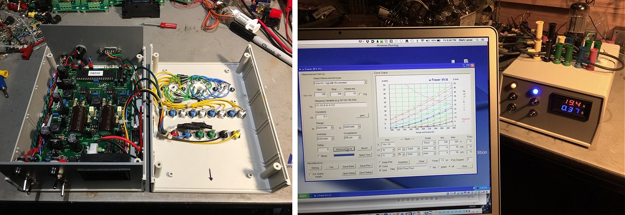
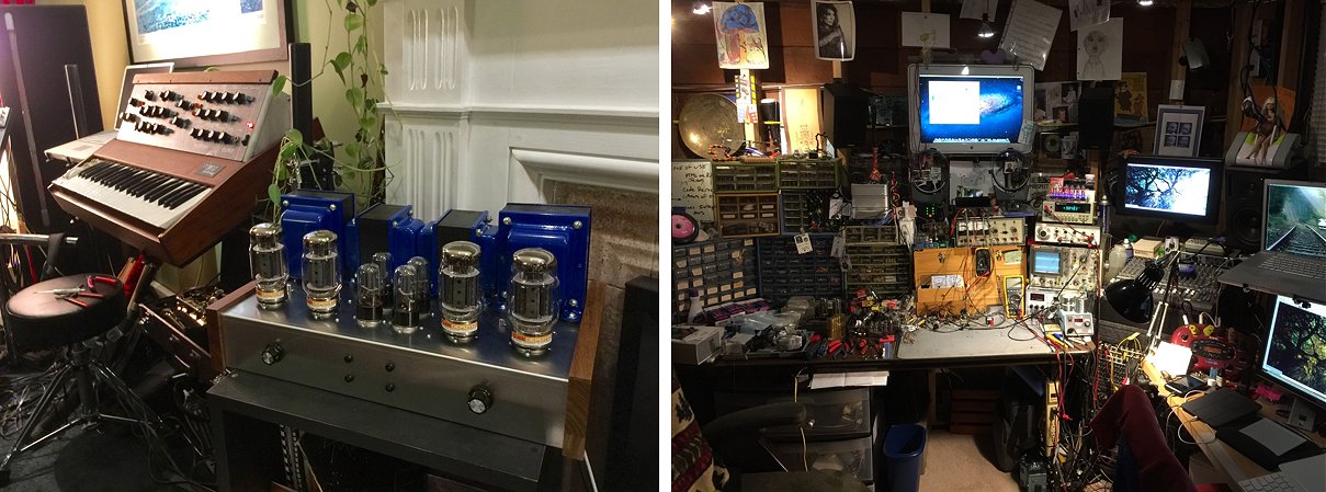
-ml
29th of December 2016, Roberto Gubellini made his own version of the uTracer!
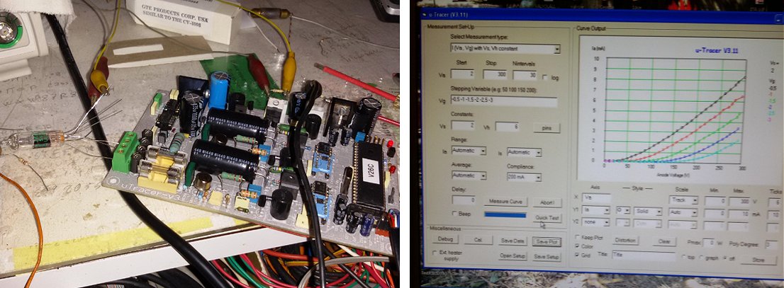
(it is now time to look for a worthy container).
Roberto Gubellini
28th of December 2016, Apparently Charles Bueche is using his Christmas holiday to finish his uTracer!
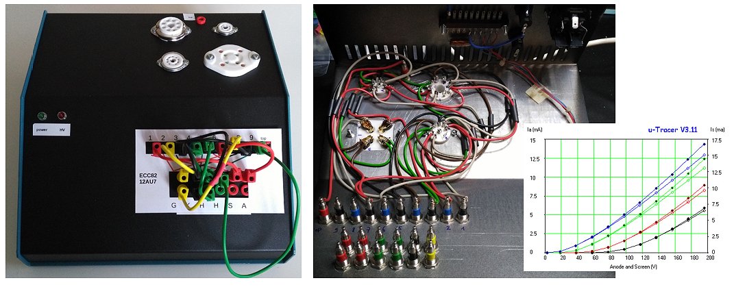
26th of December 2016, Wolfgang Thiel spent his Christmas holiday finishing his uTracer!
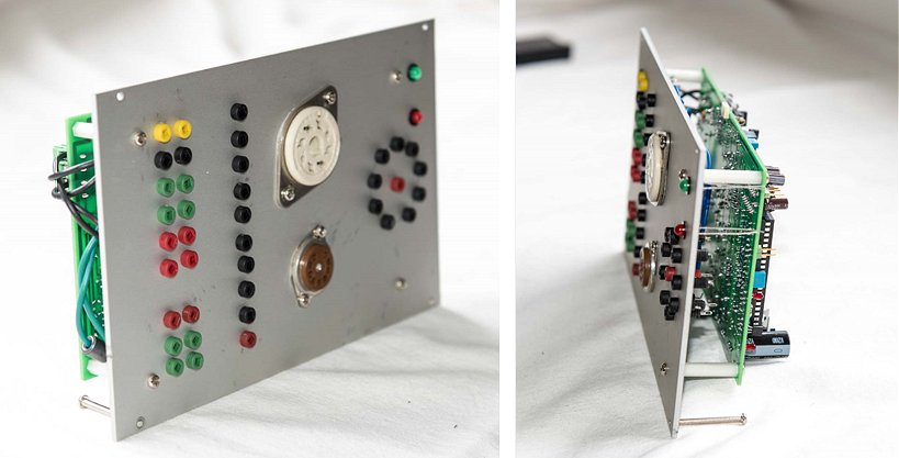
Wolfgang
7th of December 2016, Ted Walker’s uTracer is up and running!
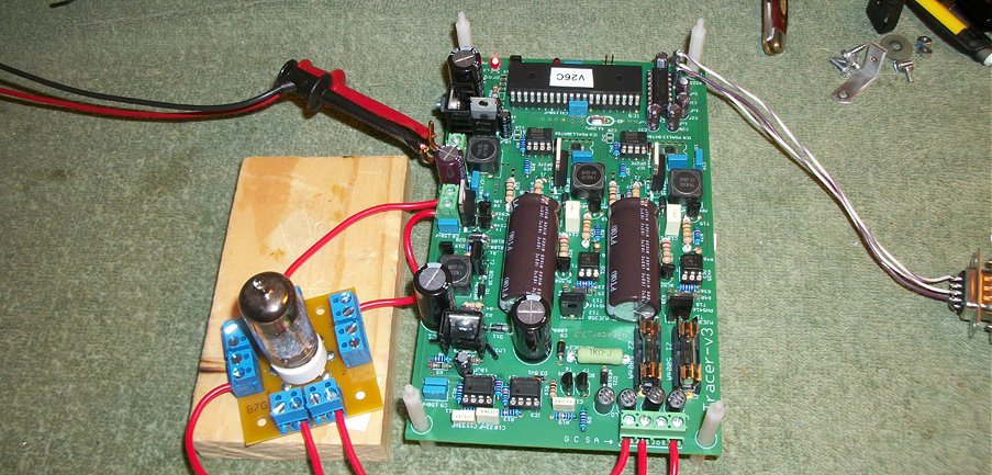
73,
Ted Walker KB5OF
Euless, Texas
29th of November 2016, Lars Ewald’s uTracer is straightforward and effective!
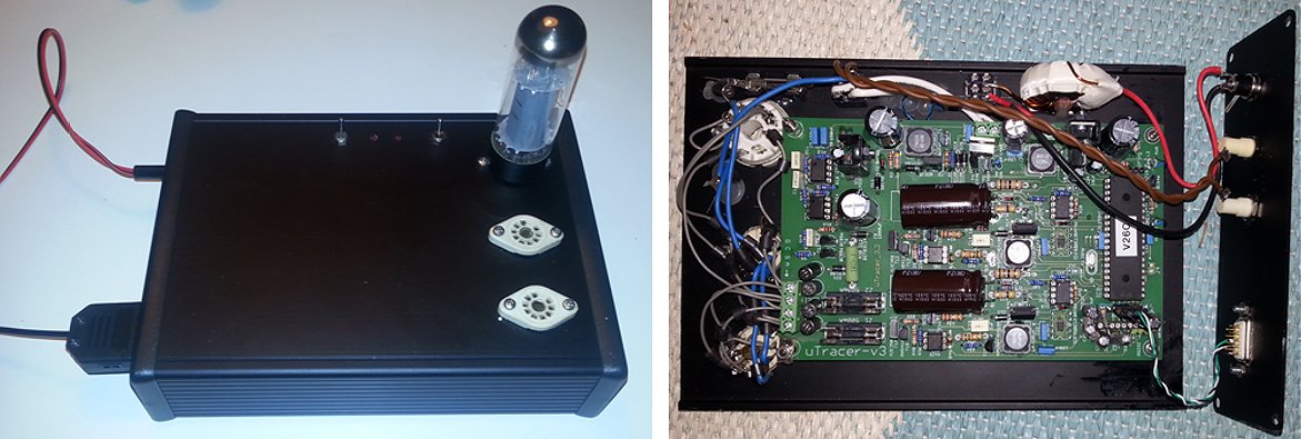
As promised a couple of pictures of my way of assembling the UTracer.
I have added 3 sockets. The first is for EL34, KT88 etc. The next socket is for EL84 etc. and the final socket is for 12AU7 etc.
For other tubes I will make a socket converters.
On the top a power switch and an external Heater supply switch is available.
I chose to use USB to Uart converter cable for the laptop connection and an external Laptop PSU.
23rd of November 2016, Gerardo Nardozza’s uTracer has come to life showing that language barriers are no obstacle!
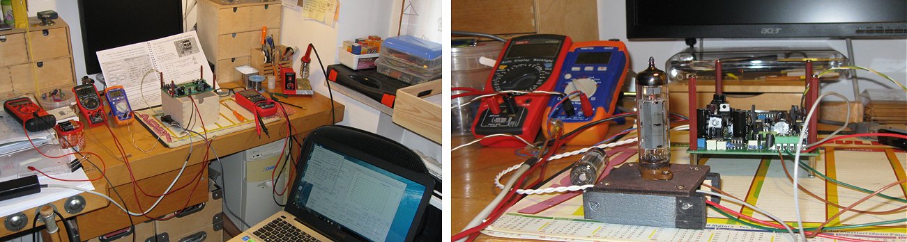
I have finished my uTracer but it still needs its final cabinet. As regards the experience it was positive, I didn't have any particular problems even if the assembly was quite long and engaging. I find the whole project interesting and very useful, I think you really did a great job.
I'm sending you some photos but in the future I hope to be able to send you some more picks of the completed kit.
I'll be happy to keep in contact and be informed about further developments.
Gerardo Nardozza (Italy)
9th of November 2016, Mladen Knezevic and Zdravko Kristic from Croatia turned their uTracer into a nostalgic work of art!
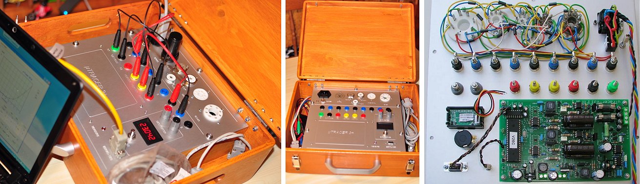
8th of November 2016, Gabriele Carnevali’s uTracer has been optimized for guitar amplifier tubes!
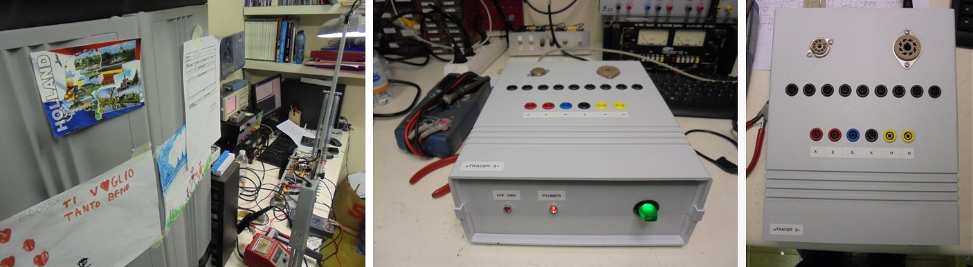
2nd of November 2016, Robert Culver used the uTracer to restore and old Tek 454 Scope to its full glory!
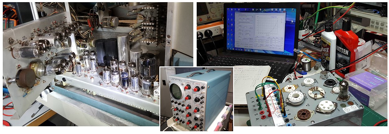
I used a similar socket interface to you.
Photos after much cleaning, repair, repainting and re-adjustment of the old Tek.
Robert Culver
VK5RC
1st of November 2016, Thomas Rehm’s version comes close to my dream uTracer!
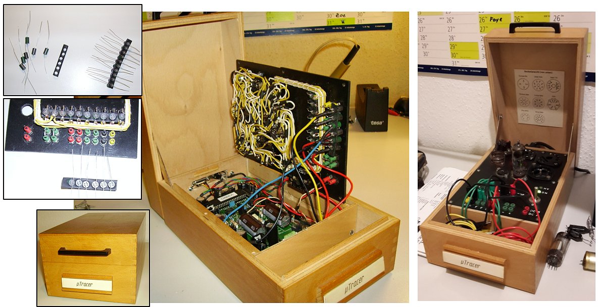
The result of this work is a very nice retro-style uTracer which does a reliable job tracing the tubes of my old radios and amplifiers.
Many thanks to you and your wife for making a kit available which enables an electronic hobbyist like me to build such a great tool.
Thomas Rehm
Germany
25th of October 2016, Robert Waldow’s working place looks like a real lab environment!
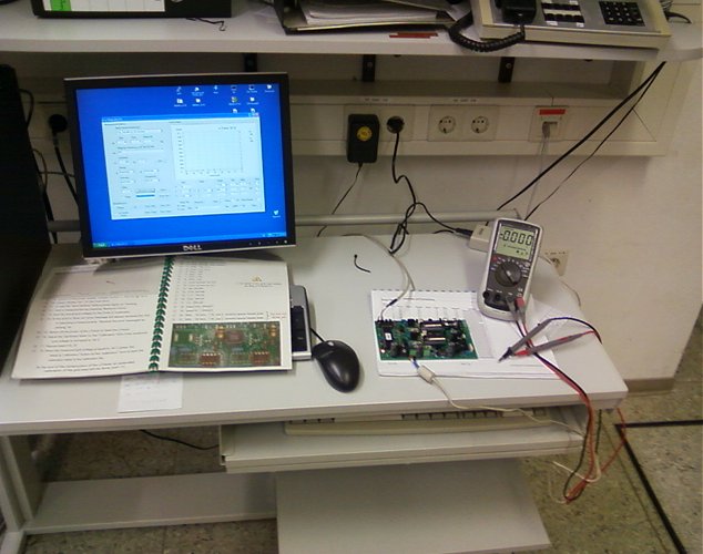
Also the GUI is great and works very fine.
Thank you for this smart tube kit.
24th of October 2016, Michikazu from Japan turned his uTracer into a handy instrument!
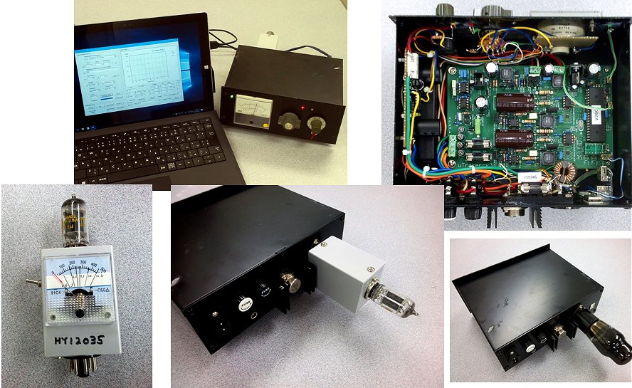
The socket was made wiring of 6L6.
I can measure it without adapters.
It's possible to supply a heater from external supply.
The meter which stuck to the body indicates the heater voltage, the
plate voltage, the screen voltage, the bias voltage and Cathodic current.
But it's ordinary.
Small adapter I made.
It's can measured twin triode one or another one by the switch.
I'm playing every day with this.
You offer me something good, and I rejoice.
And a picture is attached.
Thank you very much.
I hope to see you next time.
Bye.
13th of October 2016, Erik de Best made a quick and dirty but very functional case!
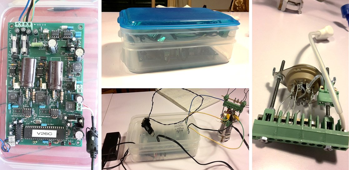
11th of October 2016, Guido Lindges has a workshop at home where he can make a beautiful case like this …. I am jealous!
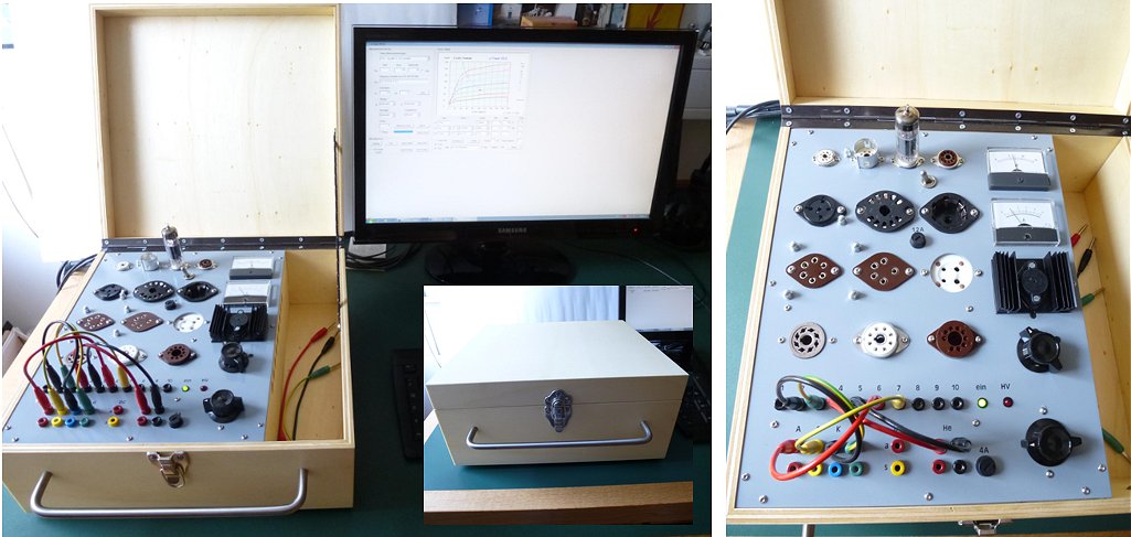
Germany
4th of October 2016, Simon Huser sent me an extensive and enthusiastic email!
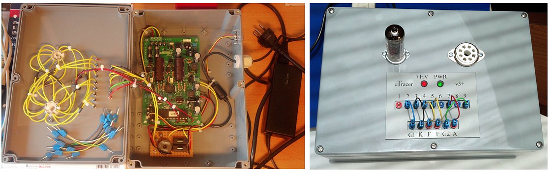
Simon Huser
Switzerland
9th of September 2016, Carey Gruszie’s uTracer is no-nonsense but very effective.
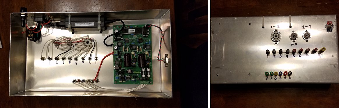
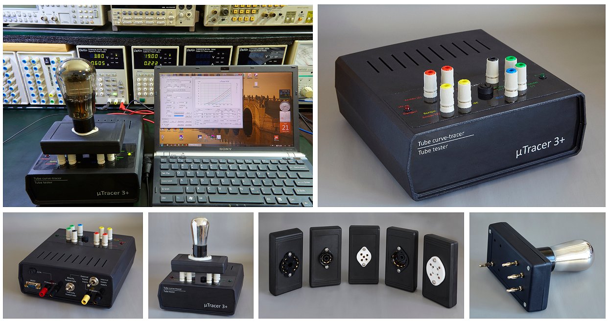
Every section was smooth and work on the first switch on.
Your work is outstanding.
Thank you very much for all.
26th of July 2016, Filip van Kenhoven built his uTracer on perfboard an he and his son Michiel made a beautiful project out of it!
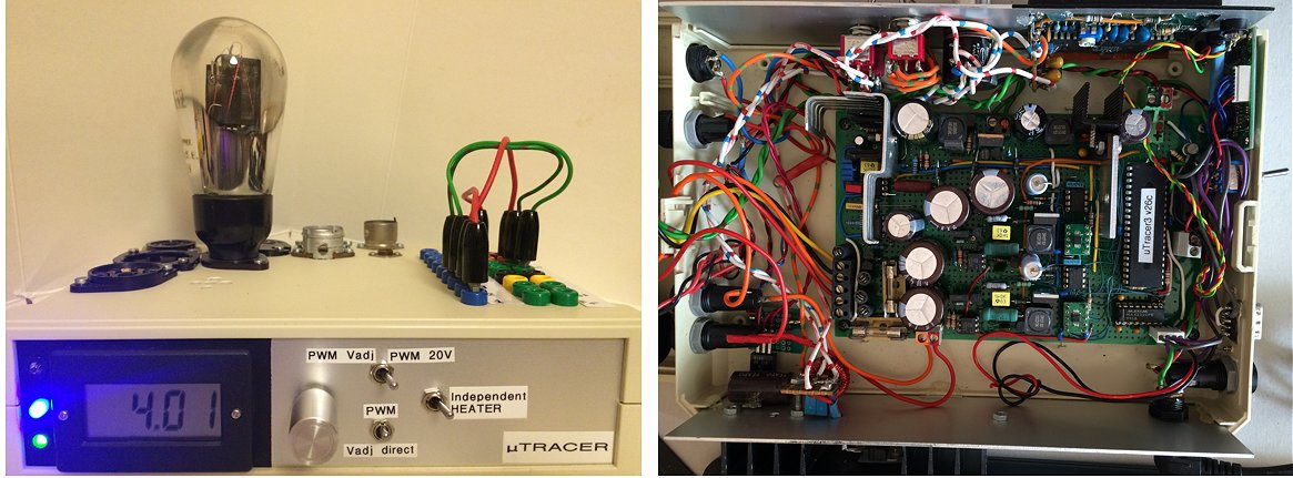
Here are some pictures of my uTracer, you’ve seen it working already on the NVHR radiofair last December.
Filip’s son Michiel (15) has no particular interest in tubes, but appears to be quite a wizard in programming, Java, apps etc.
In his spare time a wrote a “quick test”app for Anrdoid that communicates through the Bluetooth interface his father uses to communicate with the uTracer.
The calibration values have to be entered once after which they are saved.
Michiel is currently fine tuning the app and when it is finished he will make it available on Google play store!
Michiel even made a beautiful YouTube movie of the app from which I have extracted a few stills. Enjoy!
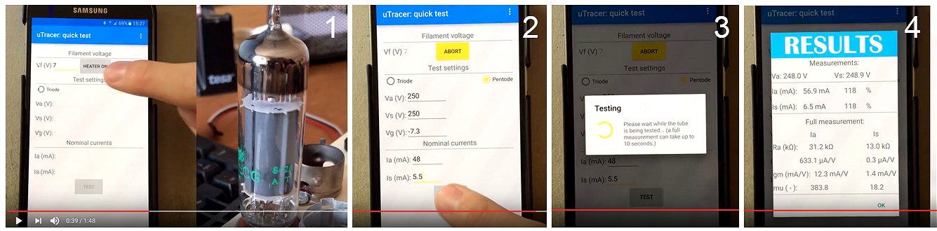
17th of July 2016, Bo Johansson made a very nice uTracer with the thumbwheel switch from a scrapped AVO MKIII!
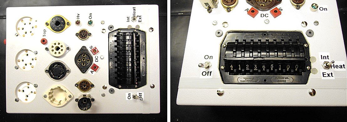
I have updated it to 400V, furthermore, I have taken the thumbwheel switches from a scrapped AVO MkIII and fitted it to my uTracer! Works perfectly!
And thank you for the excellent job you and your family have put into the project!
17th of July 2016, Grahame Marsh’s uTracer looks like a work of art and he is sharing his dxf file with us!
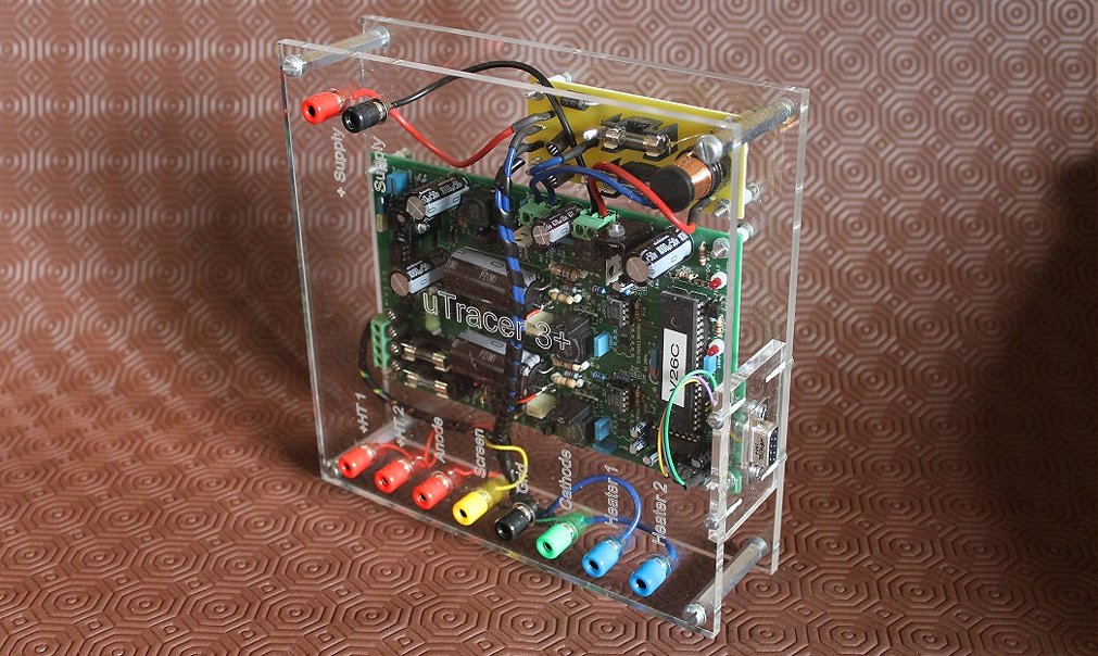
Highlands Scotland
The dxf file of Grahame’s case can be downloaded here.
The beautiful acrylic plates were ordered from ZAP! creatives.
27th of June 2016, Sven Stalbovs is happy with his uTracer!
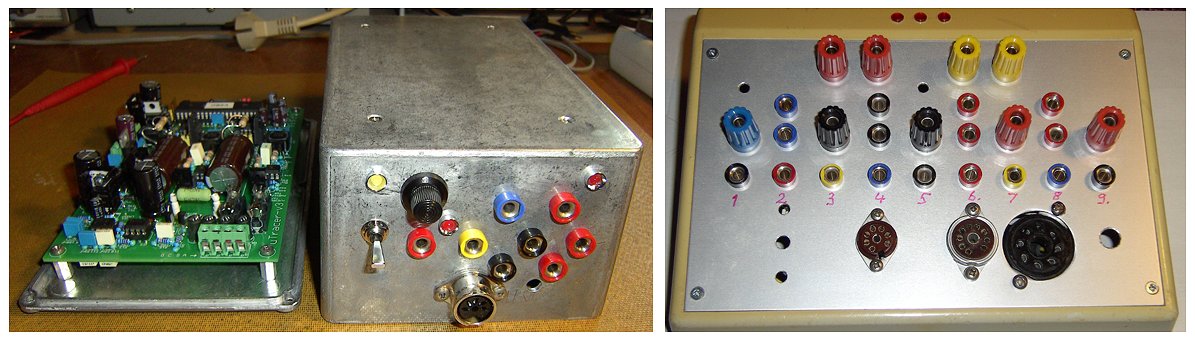
Did test some of my tubes like EL34, 12AX7 and last not least the GU50. I am very pleased to get really the diagrams for engineering judgment.
Attached some pics. The cases are recycled thus not perfect but useful.
10th of June 2016, Chris Chang from Taiwan finished his uTracer and is spreading the news in his country!
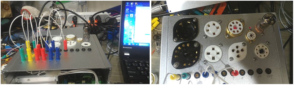
Chris Chang
View the thread on the uTracer on Facebook
16th of May 2016, Anton’s uTracer is ready to test his 20000 tubes!
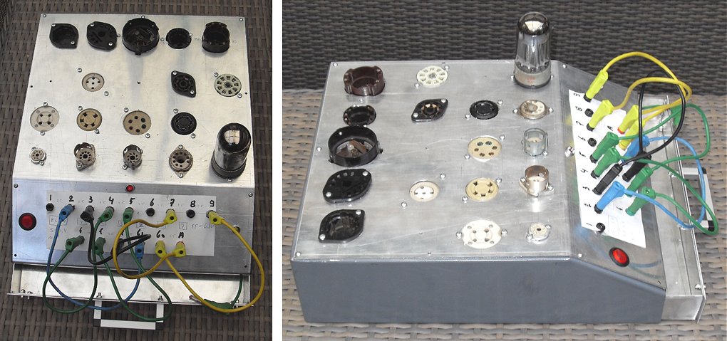
http://www.labc3.com
6th of May 2016, Detlef Kraus finished his very nice uTracer!
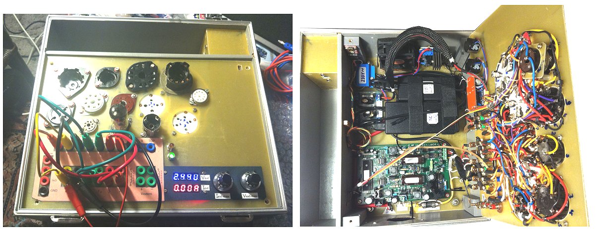
Both uTracers PCB are okay.
The wireless connection from my notebook to uTracer operates with BlueTooth and so
I have more space in my motion.
Attached are some pictures of my uTracer3/1.
At the moment I can’t use my uTracer3/2 with the GUI uTmax.
If the measure procedure lasts longer report the GUI a timeout signal from uTracer.
It happens with USB and BlueTooth connection.
That’s all I have to comment in this moment.
27th of April 2016, Steve Dillon just started the construction of his uTracer and sent me a picture of “the assembly area.” An amazing work spot, I could not resist posting it!
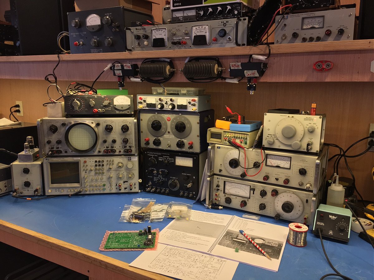
Steve
27th of April 2016, In true DIY spirit Harald Grabowsky made a fine case from leftover materials!
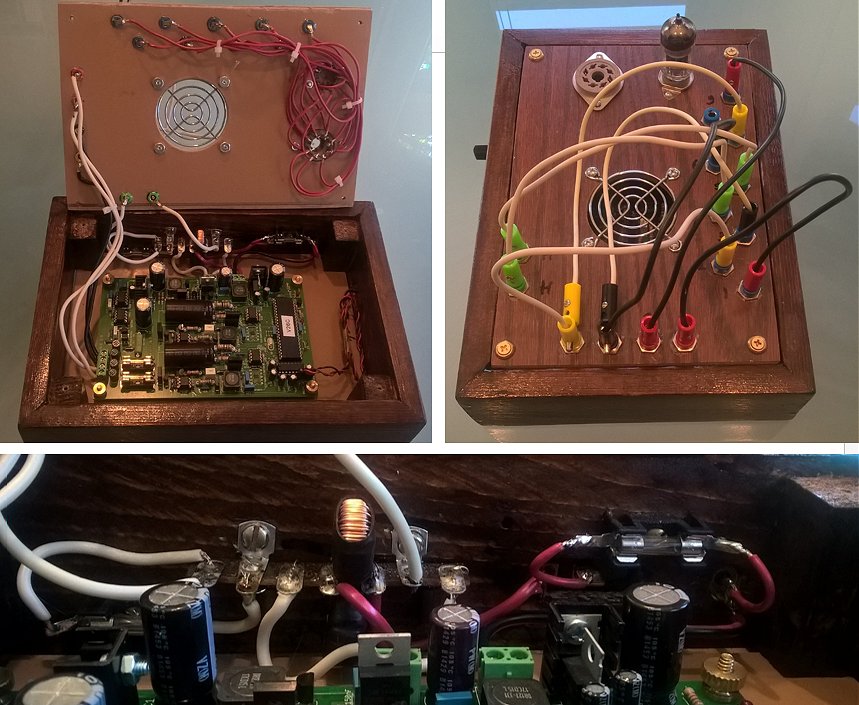
14th of April 2016, Alexander Gurskii from Belarus made his own PCB with excellent results. Compliments!
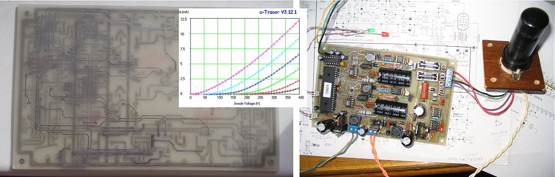
First, since your manual has the pictures of pcb, I was able to make pcb file in the Sprint Layout program, using these pictures as a background. The main problem is the impossibity to make metallized holes at home, thus, I slightly modified the pcb, adding several holes for transitions to avoid transitions through pins of the parts. Then I asked my friend Eugene and he prepared the pcb. The pictures of both front and back side of pcb are attached. Not so good-looking as your factory-made pcb-s, but quite acceptable. The transitions then were made simply by soldering little pieces of wires through holes, thus, the "double-sided" pcb was created.
During the test, 5 issues were located, all of them were caused by the lack of conductivity (bad trace or crack in the transition between sides). These defects sometimes were even invisible, and in some cases I simply wired the end point of the traces on the back side. One can see 4 wires in the final pictures of pcb. Not so beautiful but safe.
The 5th issue was bad ground contact of one PGA113, fortunately, far from its package.
I replaced some parts by similar types, I think it is not so interesting.
Finally, I attached the pictures showing the very first use of this device today: the test of the soviet 6P9 pentode (=6AG7), and the test of the soviet 6N9S double triode (=6SL7-GT), as well as the results (plate curves).
sincerely,
Alexander
6th of April 2016, Ferdi Uitenbroek reported his uTracer working. He has plenty of space for more sockets!
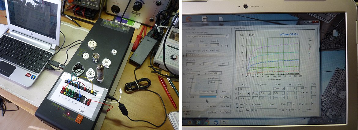
Als het nodig kunnen er nog een aantal buisvoeten bij.
Hartelijk dank voor jullie hulp en service, aan het maken heb ik ieder geval prettige uurtjes beleefd.
De foto`s laten de testopstelling zien van een EL84 (overigens geen beste).
Ferdi Uitenbroek
27th of March 2016, Sometimes I stumble on internet over a beautiful built description quite by accident! like this one here
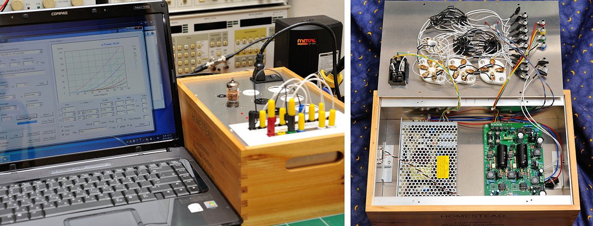
23rd of March 2016, T.Mori from Japan reported his uTracer working.
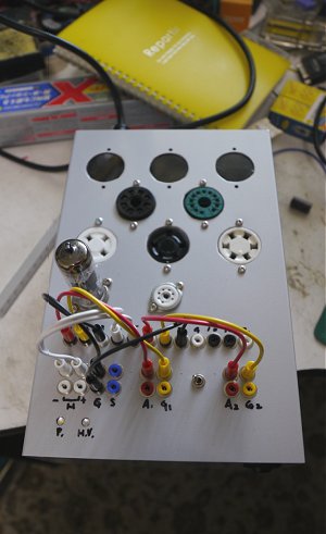
27th of February 2016, Paul Newman from New Zealand made a splendid portable uTracer!
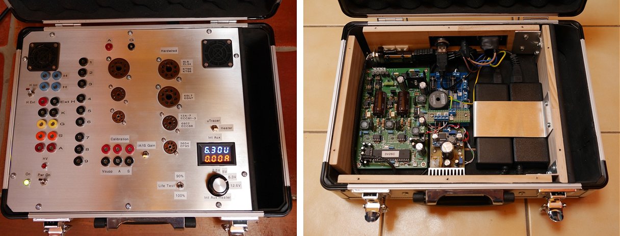
New Zealand
23rd of February 2016, Jim Yates finished his very nice uTracer.
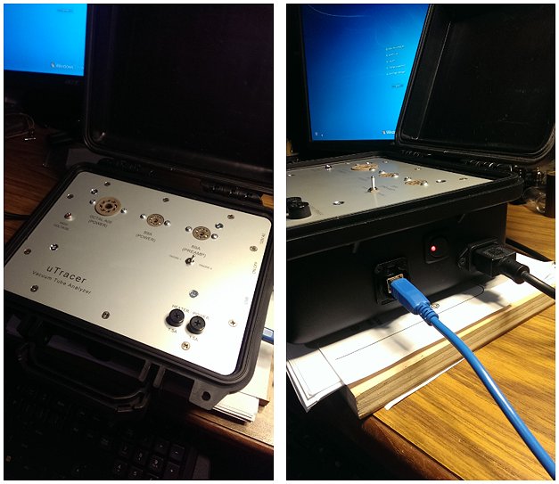
I couldn't be happier with the outcome.
Also thanks again for pinpointing the loose solder joint on the inductor in the anode section via email no less which saved me hours of headache.
16th of February 2016, Allen Gardner from Amgard electronics made a very efficient and logic case around his uTracer!
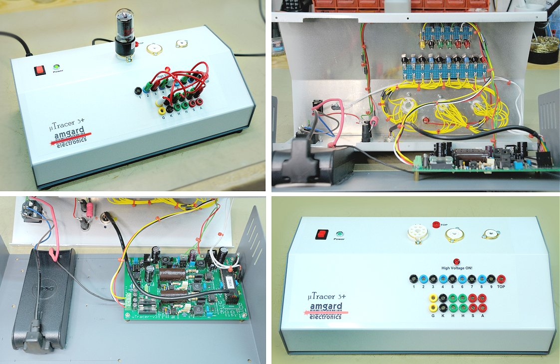
This is just to say how much I enjoyed building the uTracer. Your documentation is a real joy to follow, it far exceeds that which is supplied with 'commercial' kits.
Allan Gardner
6th of Februari 2016, Jose’s uTracer is very stylish and compact!
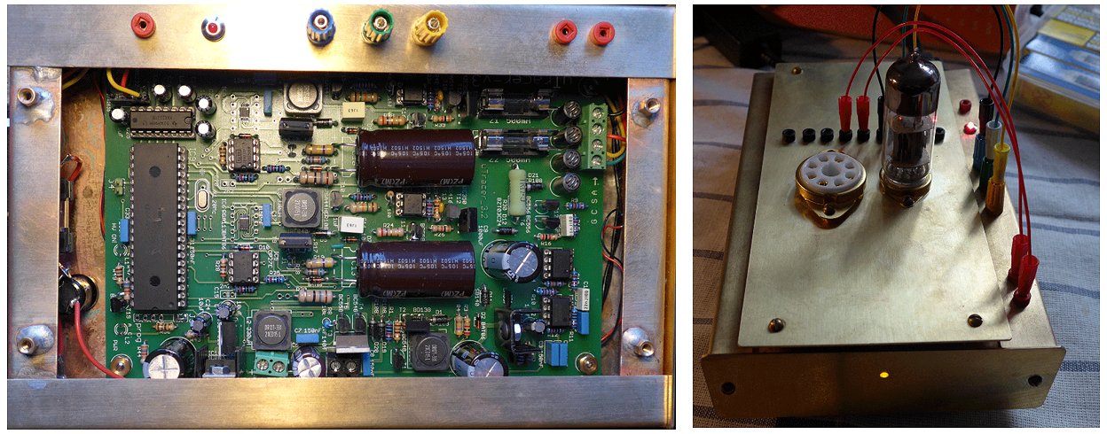
2nd of Februari 2016, Alex from Germany is certainly happy with his uTracer!
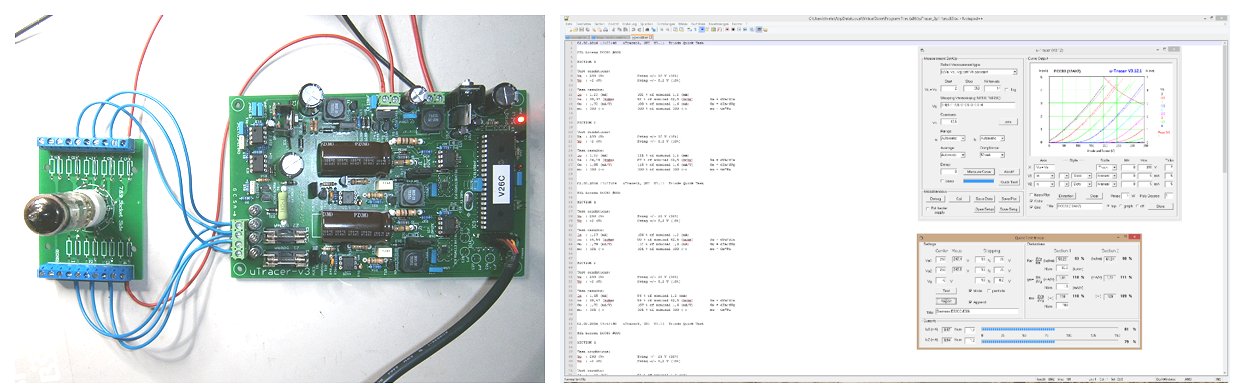
Thank you for the very well done documentation, it´s bullet proof! All steps have been easily assembled though I do not like this transistor stuff with PCB... :-)
Alex
29th of January 2016, Miloš from the Czech Republic turned a whole pile of components into a very beautiful uTracer!
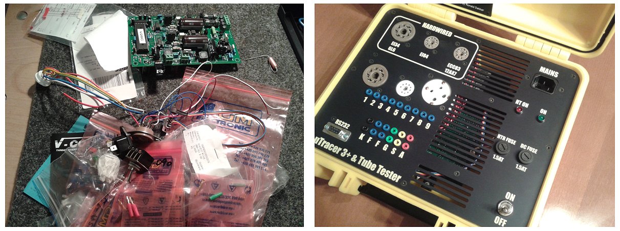
Miloš
19th of January 2016, Christoph Bohr finished his uTracer (again) and sent me a nice testimonial!
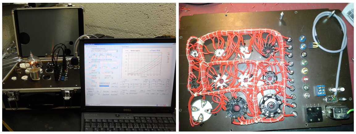
4th of Januari 2016, Yoshikazu Tanabe from Japan created a beautiful wooden box for his uTracer. Click here to visit his website.
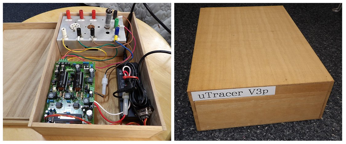
Marie and Ronald
I have just assembled it with V3p updates.
I attached some view of my uTracer.
I tried to measure some tubes I have.
It shows the characteristic of tube visually. It is easier to judge good
or not.
I am looking forward to see Version 4.
JA3WZT/Yoshikazu Tanabe (Japan)
26th of December 2015, Sebi Carjan sent me a few pictures of his very nice version of the uTracer.
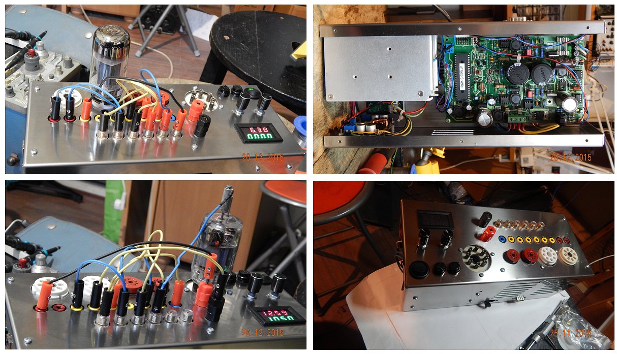
Sebi
17th of December 2015, Michael Fleming’s uTracer: indicator light, rotary switches and tubes, a boys dream, fantastic!
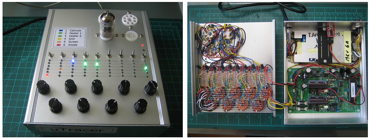
Michael Fleming
5th of December 2015, Another beautiful uTracer has come to life, this time in the Czech Republic!
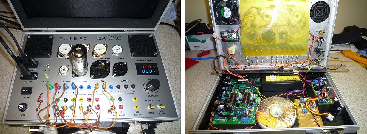
29th of November 2015, Florian from Bavaria made a beautiful wooden box around his uTracer!
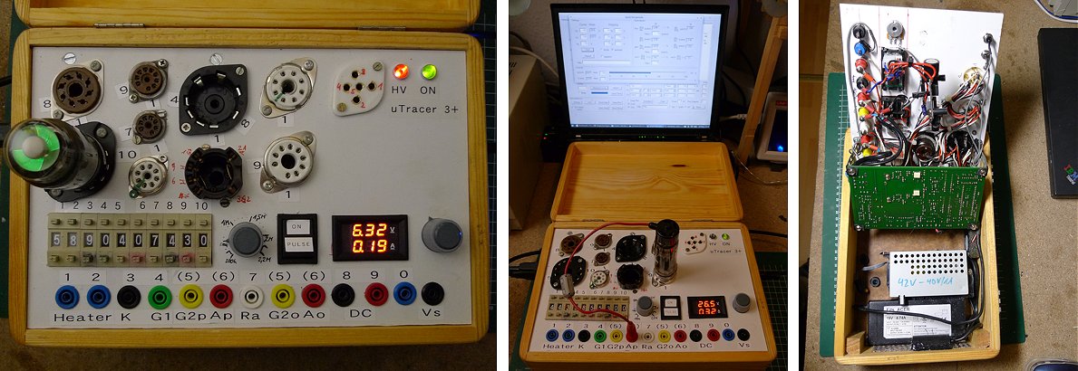
- a separate Supply with some 42-43V, with a Step-down to generate higher filament Voltages.
- the Voltages from the HV-caps to the Panel,
- a Potentiometer (0.2-2.2 MOhm) from Anode to one Connector
with the Puswheel-Switches i select the source per Socket-Pin, so i prevent shortcuts on µtracer-Outputs.
I'm still not sure whether the switches will durable withstand the 400V, till now it's ok.
Florian
25th of November 2015, Joe Carpenter from A to Z Guitar and Ampworks LLC will use his uTracer in his shop!
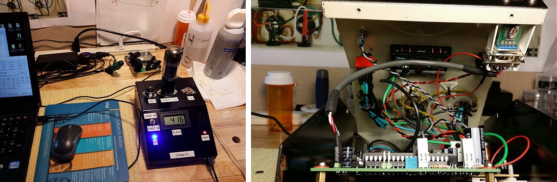
A to Z Guitar and Ampworks LLC.
22nd of November 2015, Shi Haizhou from Beijing, remains very enthusiastic about his uTracer!
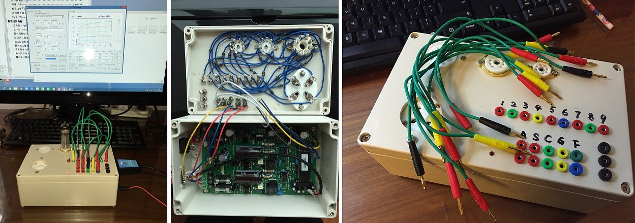
12th of November 2015, Paul Wilton reports another uTracer alive!

Paul
1st of November 2015, Shi Haizhou from Beijing, China reported his uTracer working!
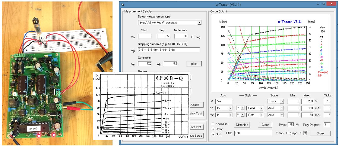
Cheers
Louis
15th of October 2015, Marcello Borini reported his uTracer working with the GUI running in Oracle’s Virtualbox under openSUSE, read more here
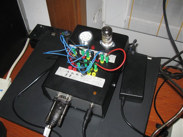
Marcello
15th of October 2015, Andres Tarik gave an update of the state of his uTracer in an “outdoor ambiance”
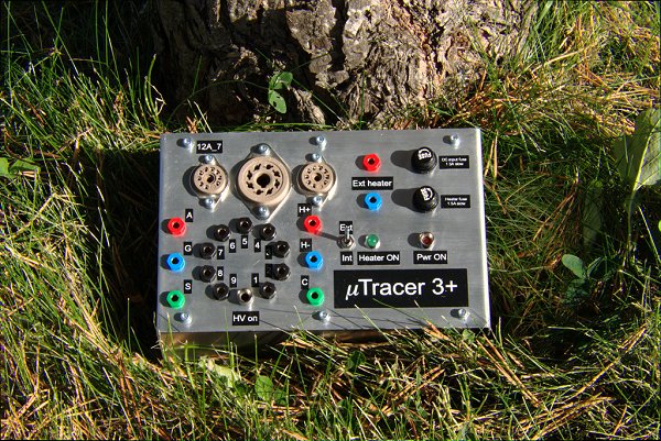
9th of Oktober 2015, Vladimir Julius (OK1VJ) reported his uTracer working!
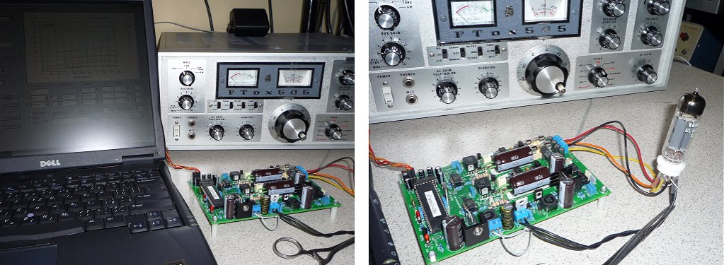
Several pictures in the Annex
OK1VJ my amateur radio mark.
30th of September 2015, Zsolt Botos’s uTracer has a double row of rotary switched in a small case, a wiring nightmare, but ... beautiful!
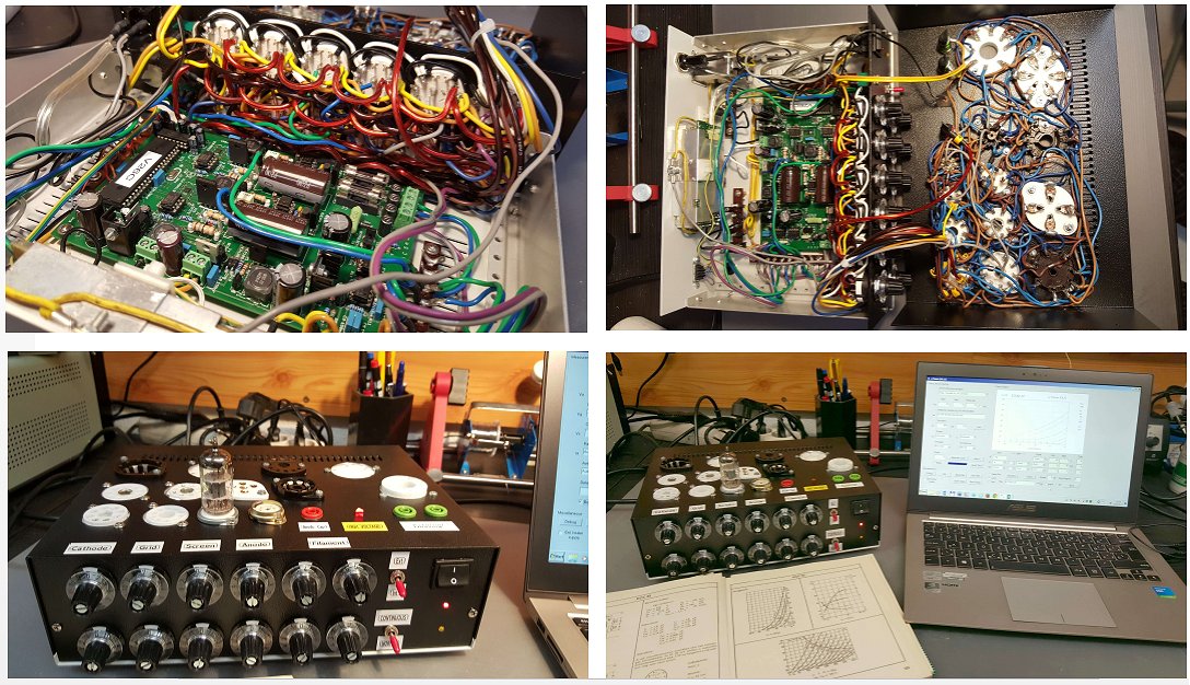
Zsolt
22nd of September 2015, Simon Wegler sent me an extensive testimonial and some pictures of his very compact uTracer!
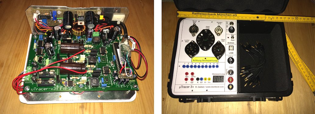
hi Marie-José,
After receiving the kit I built it within a week time and it worked flawlessly from the beginning. A truly well engineered and superbly documented device that was very easy to build, even for a "non-IC-guy" like me. I loved it. :-)
After I had finished populating the pcb I had a look on the great builds from all over the world that you show on your homepage. Especially Joe's TTT-3 caught my eye and I decided to try something similar.
Please the the attached files for an impression of my attempt.
I made two small modifications: First I added an "adapter"-board to the socket which was originally intended for the MAX232. Therefore I am now able to directly add an USB-TTL-converter and a TTL-Bluetooth-converter to the board without the need of level shifting. So now I have the choice which interface I want to use.
Second modification is an additional heater-board, which unfortunately is not yet in use, I am still struggling to convert the "squareroot"-PWM to a linear voltage to program a LM2576HVT. Would it be possible to have a non square rooted PWM output? Maybe in a next release of the firmware? For the time being I use external heating.
The finished enclosure holds space for the programming cables (standard 2 mm lab connector), the power supply (not shown here, just a standard notebook PSU) and even a small multimeter (Benning MM P3 with modified cables with 2 mm connectors, also not shown).
Thanks again for this great kit, it is a lot of fun and very useful.
Simon
8th of September 2015, Brian Munson’s uTracer is in one word “stunning” !
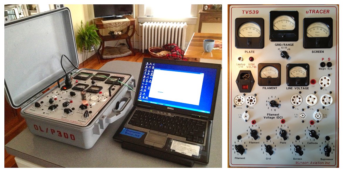
The uTracer was the best kit I ever built. The verification tests during the building stages insured the curve tracer would operate correctly when finished.
6th of September 2015, Ilkka Juurikko from Finland introduces the “lunch-box” uTracer!
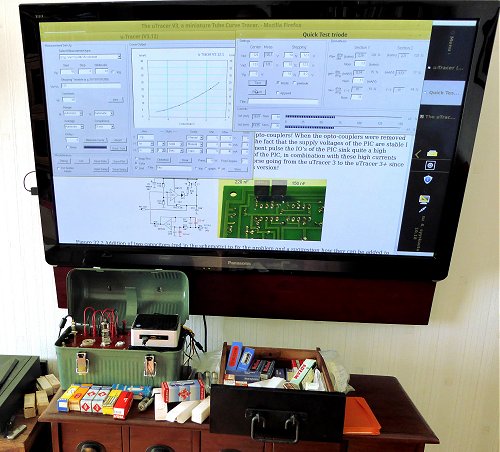
-ilkka
20th of August 2015, Matt Beardsworth’s uTracer is, as he put it himself, straightforward, but nevertheless very useful!
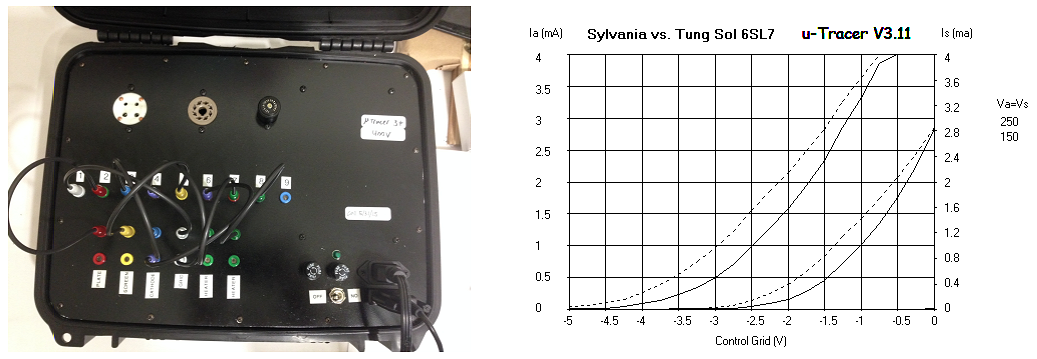
Matt
17th of August 2015, Winfried Hirsch made a beautiful case for his uTracer using 3D printing, a first!
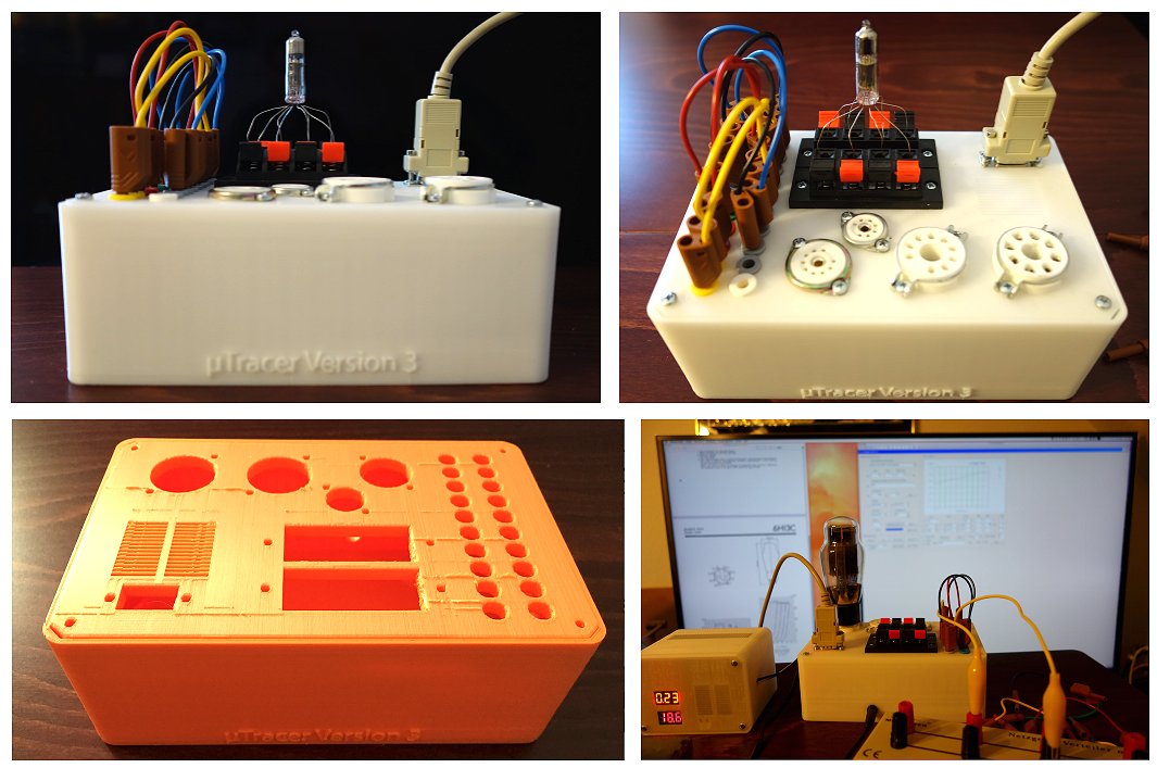
- Portable operation with a laptop or minicomputer, LiPo battery driven supply (easy to accomplish since the uTracer generates all the needed voltages)
- 3D printed case for my version of uTracer which is just printed without the need for drilling holes.
- Another thing was that I do much with submini tubes and it took long for me to find a way to build a practical setup to measure this beasts.
13th of August 2015, Joakim has a very nice implementation of his uTracer with some “programmable” sockets and some “hardwired” sockets for common tubes.
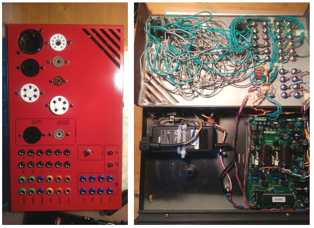
Joakim
24th of July 2015, Ken Klein is very pleased with his uTracer!
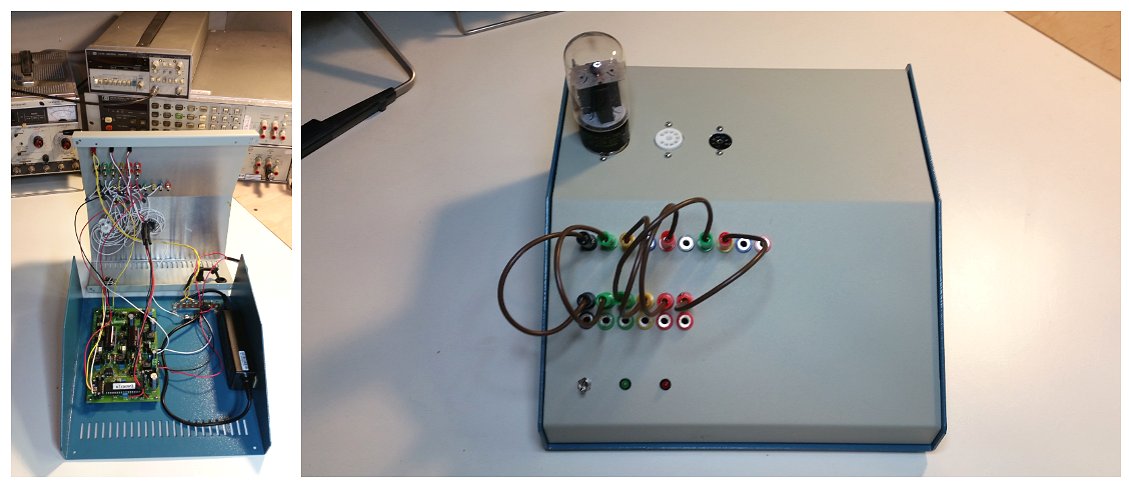
21st of July 2015, Luis Fernando’s uTracer – the second in Brasil – is an example of a straightforward and efficient construction!
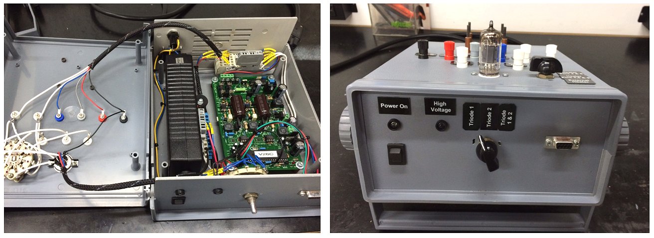
13th of July 2015, Zoltan Benko’s uTracer is a statement of pure craftsmanship!
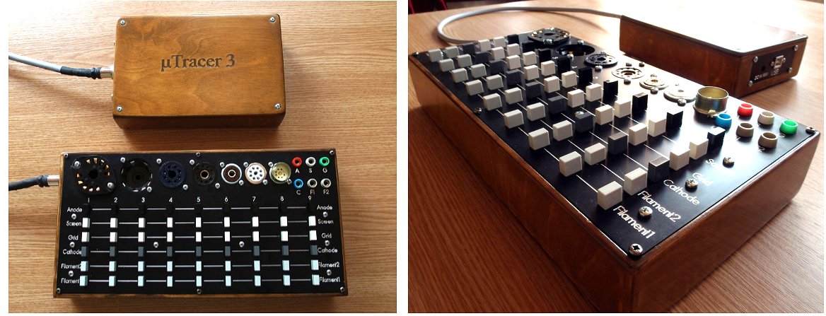
Zoltan Benko from Hungary
5th of July 2015, Allan Wyatt Curator of the National Valve Museum wrote a nice review over the uTracer
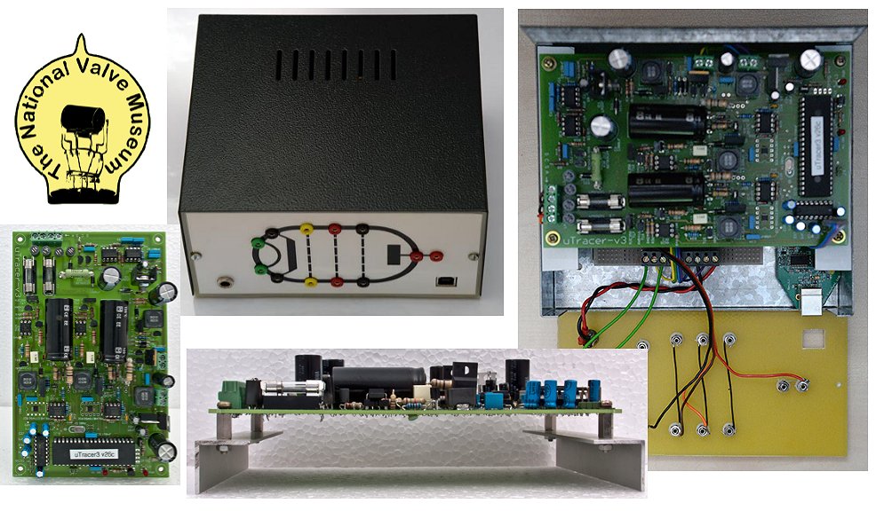
5th of July 2015, The beautiful small uTracer of Keith Jones made me quite jealous!
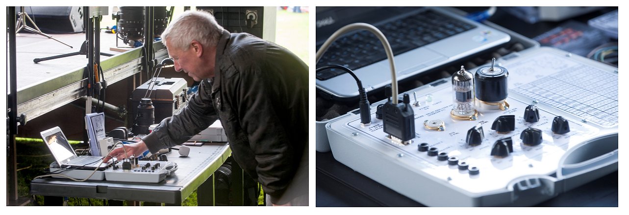
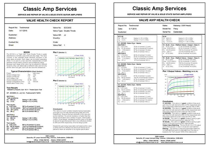 Hi Ronald & Marie-José
4th of July 2015, Teemu Maijala from Finland reports his uTracer working!
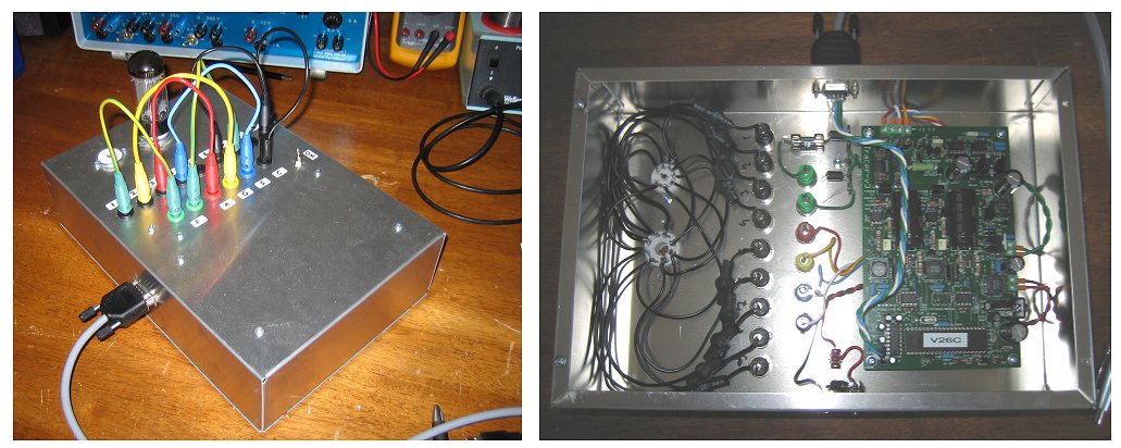
4th of July 2015, I am happy to learn that Erwin Schumann from South Africa is using his uTracer extensively!
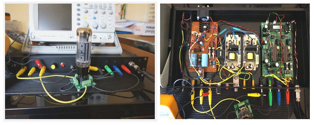
Cape Town
South Africa
4th of July 2015, Martin Manning sent me an update on his uTracer
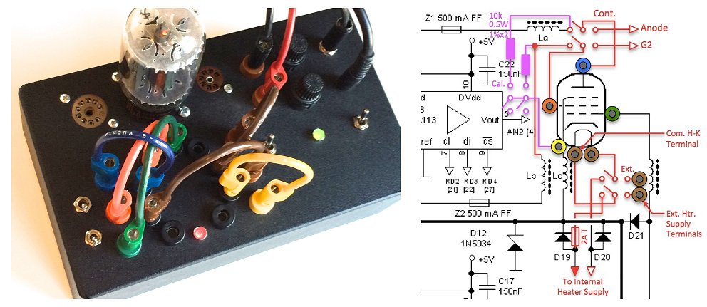
4th of July 2015, Simonson Lasse shared a few pictures of the matching of an impressive FU-29 tetrode.
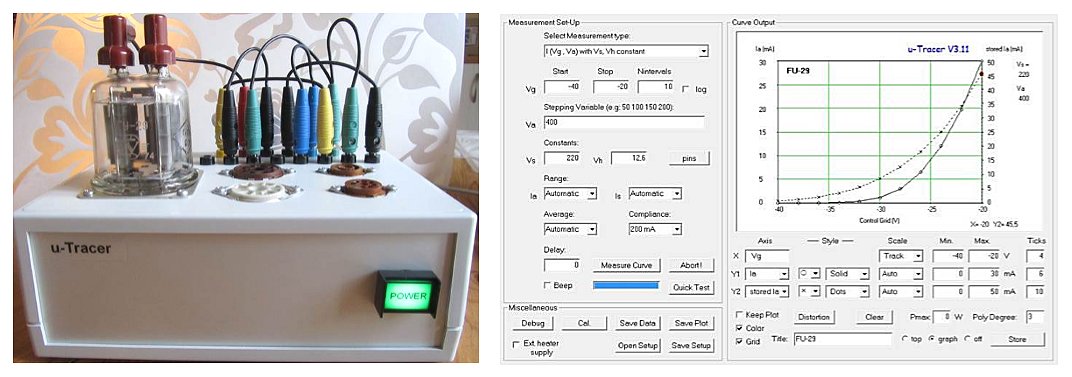
1st of June 2015, Bodo Fuhrmann reports his uTracer working.
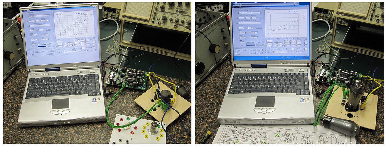
It took only some hours, one afternoon. The manual was very detailed,
especially the point by point steps with hints...
One feels, "the kit was made with love".
I attach some images of first tests without a case (as I know myself,
I never will construct one)
I use a more than 10 years old laptop with XP and serial interface an
some breadbords with tube sockets from a former tube tester project.
3rd of May 2015, Norm Campbell reports his uTracer working and he has a useful tip regarding the USB-2-Serial converter.
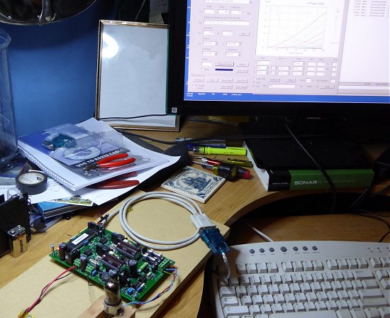
Norm
30th of April 2015, Alexandre Torchelsen Feldens has brought the first uTracer to Brazil!
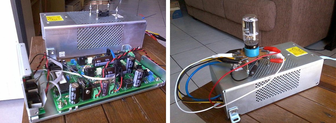
Utilizei largas "miçangas de ferrite" (ferrite beads) a fim de eliminar possíveis oscilaçőes. Tal medida provou-se vitoriosa: nenhuma válvula em boas condiçőes testada oscilou, incluindo tręs E810F!
Eu ia usar adaptadores montados com conectores DB-25, porém como eu percebi que vou testar muitas válvulas com pinagens diferentes, eu optei por algo mais arriscado: deixei os terminais de teste com garras jacaré, e eu simplesmente os conecto nos pinos corretos, na hora do teste. Isto requer mais atençăo a fim de evitar trocas de pinos ou curto-circuito entre as garras ou entre elas e a carcaça. Porém como geralmente eu trabalho desta forma em laboratório "desde sempre", estando acostumado a este processo, está OK assim para mim.
Agora centenas de válvulas estăo ŕ minha espera para serem testadas!
Mais uma vez, muito obrigado por produzir um kit bem organizado e com inúmeras opçőes de funcionalidades!
I used wide ferrite beads in order to eliminate possible oscillations. This measure proved successful: no valve in good condition tested oscillated, including tree E810F!
I would use adapters fitted with DB-25 connectors, but as I realized that I test many valves with different pinouts, I opted for something more risky: let the test leads with alligator clips, and I simply connect the correct pins on moment of the test. This requires more attention to prevent pin exchanges or short circuit between the alligator clips or between them and the housing. But as I usually "always" work this way in the laboratory, I am used to this process, so is OK for me.
Now hundreds of valves are waiting for me to be tested!
Again, thank you for producing a well-organized kit and with numerous choices of features!
From Foz do Iguaçu - Paraná - Brasil
4th of April 2015, Bjřrn Aaholm reported his uTracer up and running!
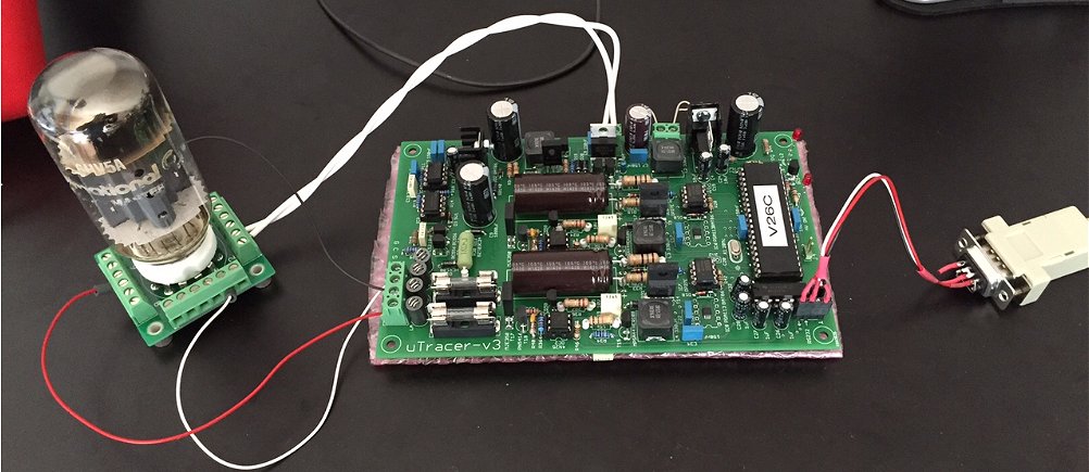
Bjřrn Aaholm
Denmark
1st of April 2015, Leung Hok Man from Hong Kong send a few photo’s of his very complete uTracer
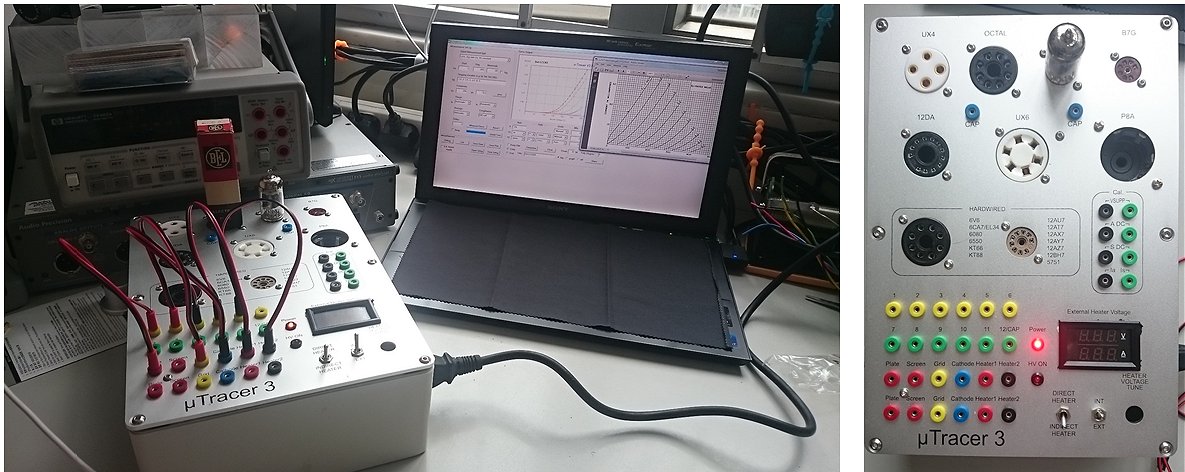
How are you?
I feel very sorry that for the delay of the photo of your product.
This product is very good for me and I using the Cost RMB 40 Bluetooth COM port is very good.
But I using the Pad with resolution 1280 X 768.
I cannot display all the detail for on the program.
Please enjoy the photo and looking forward to your update version.
Thanks.
Leung Hok Man from Hong Kong
24th of March 2015, Andres Tarik’s uTracer in Tallin, Estonia is up and running!
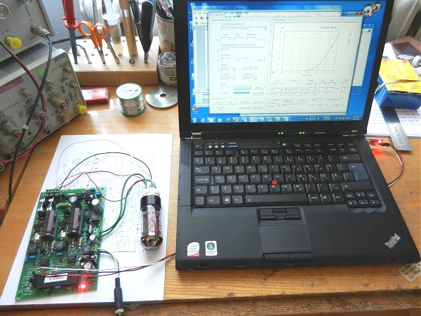
Andres Tarik
2nd of March 2015, Roger Bentley’s compact uTracer can serve as an ornament on any drawing room table!
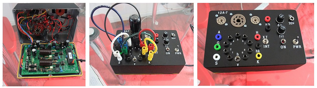
Roger
1st of March 2015, Rudolf Moers finished his uTracer!
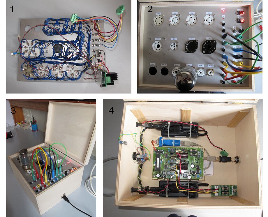
17th of Februari 2015, Rudie Dorrepaal reported his uTracer working!
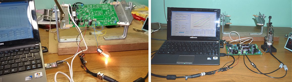
Rudie
17th of Februari 2015, Semir Nouri uses a plug system to connect different tubes to the uTracer (click here for a schematic of the wiring), after a small incident with two exchanged voltage regulators his uTracer is now running fine!
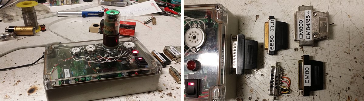
Hi Ronald,
15th of Februari 2015, Philip Jones’s very compact uTracer is especially built for the testing of the tubes in his guitar amplifier(s).
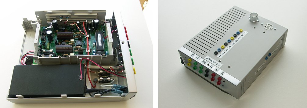
13th of Februari 2015, Luke Robertson’s uTracer: designed in the Netherlands, assembled in Canada!
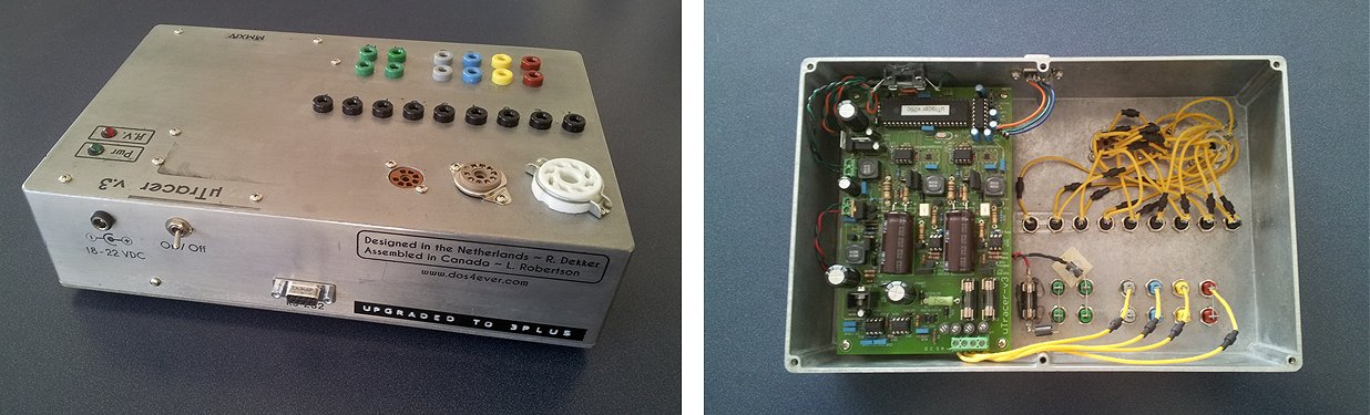
Luke
31st of Januari 2015, After a small hiccup also Philipp Mittelstaedt’s uTracer is up and running!
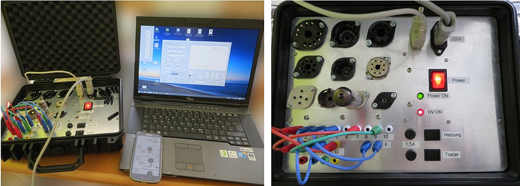
Germany
20th of Januari 2015, Herbert Jeschke’s uTracer has a huge number of sockets and plenty of space for more!
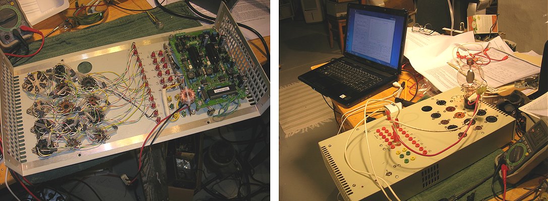
18th of Januari 2015, Tudor the Zoete’s uTracer implementation resulted in a very nice and compact piece of equipment.
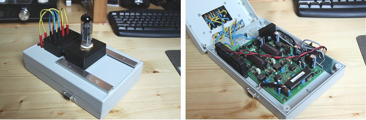
14th of Januari 2015, Francisco Martin Garcia from EDINTEC build his uTracer in the well-known fashion.
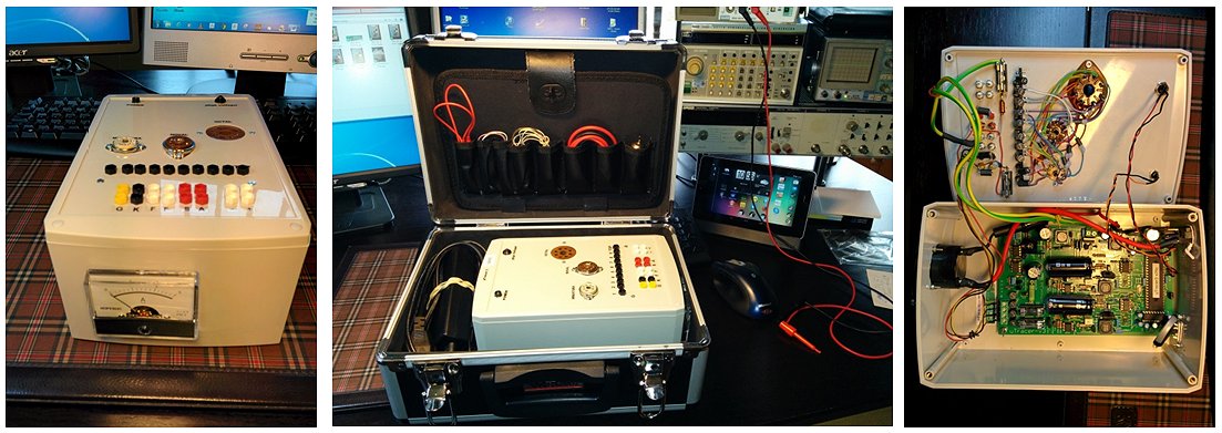
13th of Januari 2015, Christoph Krüger from ”Radio-Museum Linsengericht e.V” uses an adapter system to connect different tube sockets to the uTracer.
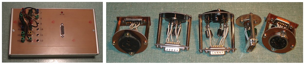
I plant it for max 12pins (Compactron).
All Pins, which might be G1, got an additional Induktor to avoid oscillation. A test with a D3a (35mA/V) was also successful.
Christoph Krüger
9th of January 2015, After a few hiccups, Ian Sefchick’s uTracer came alive without any problems!
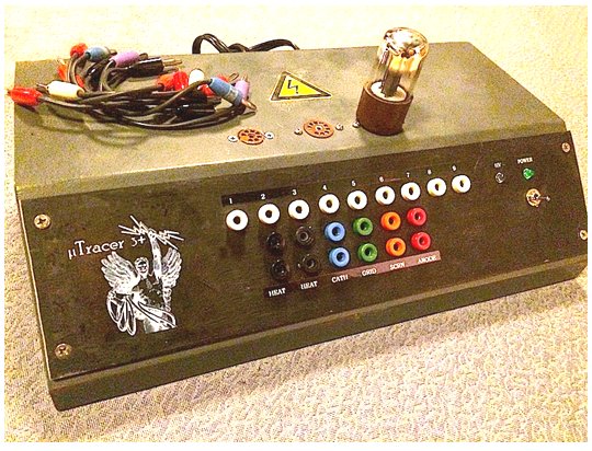
Ian
31st of December (!) 2014, Joe Leskovar from Canada is the first to a report an uTracer3+ finished! His stunning TTT-3 (Tube Tester & Tracer) - powered by uTracer3+ - is a miracle of compact construction!
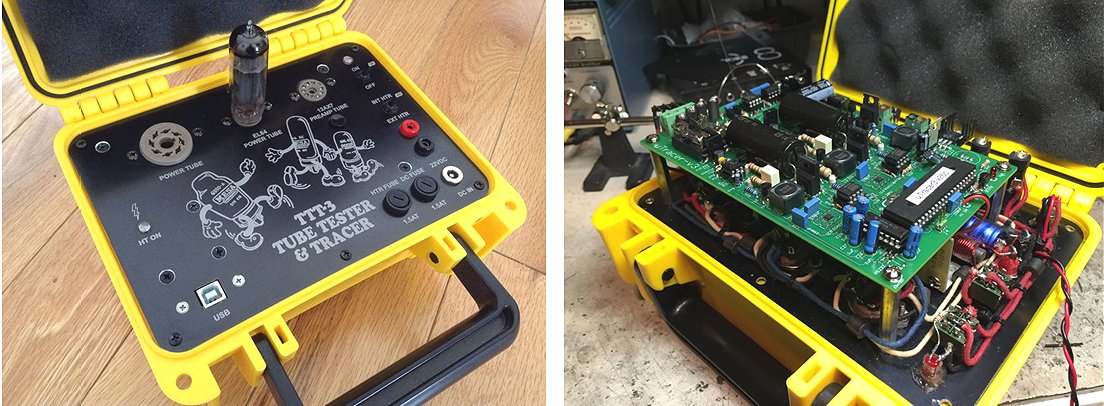
I finally finished my uTracer!!!!... I guess I waited just long enough to implement the 3+ specs..
Although it was a long time coming, since I had the case/ panel made up in March, everything calibrated up and it works with no difficulties...
Info here..
http://www.stagecue.com/utracer.html
Wishing you and your family a Happy New Year.
19th of December 2014, The wonderful uTracer implementation of Thomas Mayfield is something in between an instrument and a work of art! It must be the ultimate dream of every man who (like me) has within him a boy hood fascination for tumbler switches!
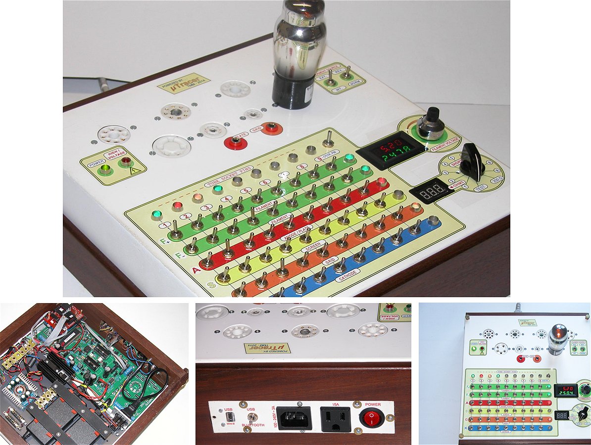
21st of November 2014, Ruud Jansen (71) from Holland reports his uTracer working! Click here to his weblog on the project (in Dutch).
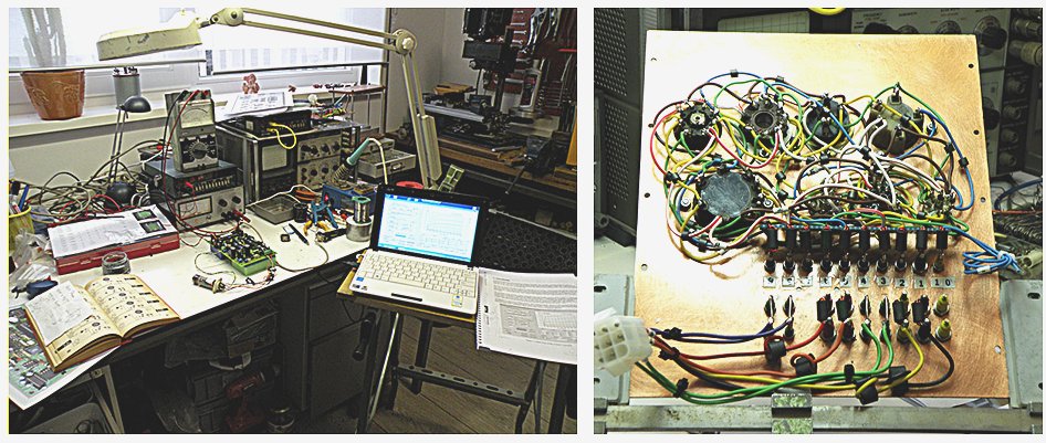
16th of November 2014, Pieter Bareman made a nice box for his uTracer and demonstrated it on the “repair-day” of the NVHR.
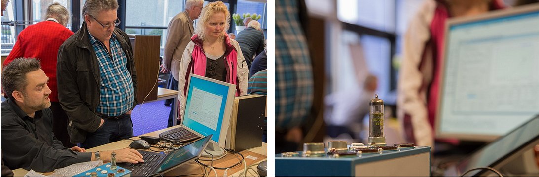
2nd of November 2014, Peter Block has his uTracer working and he is very pleased with it!
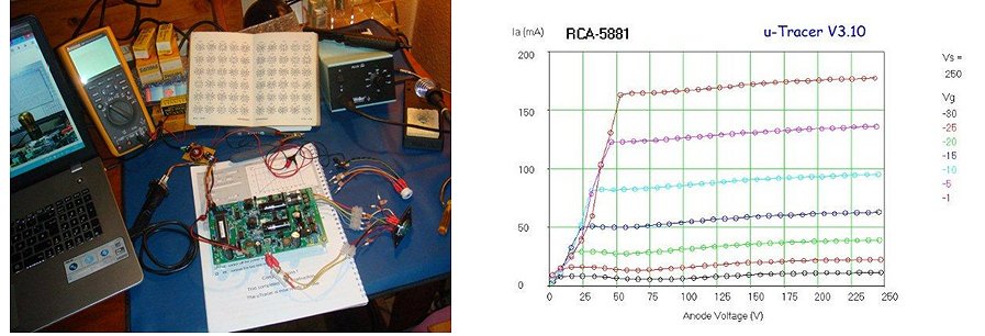
2nd of November 2014, the case for Steve Blackmore’s self-repairing uTracer is finished!
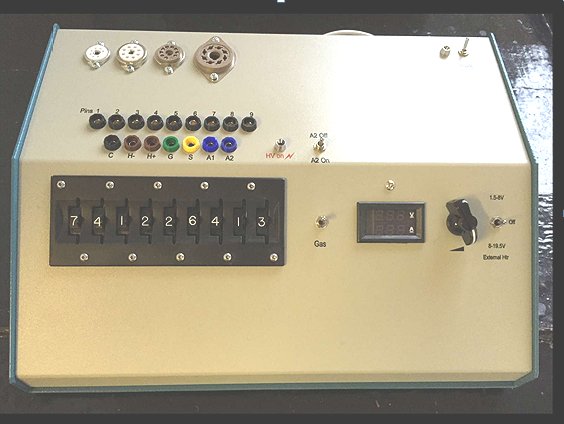
1st of November 2014, Klaus Haber reports his uTracer working, and he is a bit surprised it works so well!
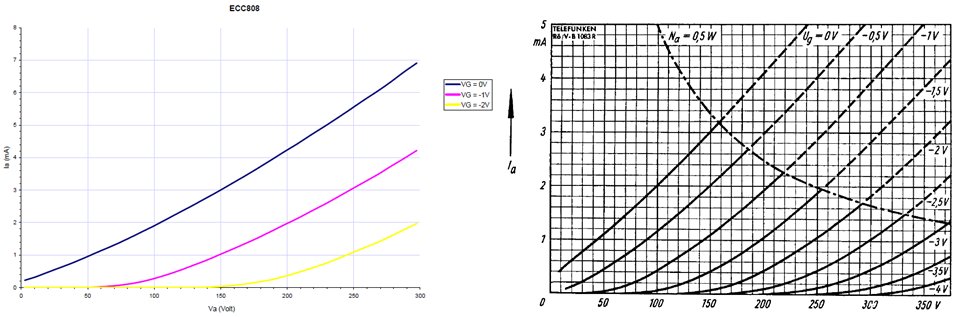
Hi Ronald,
22nd of October 2014, Thomas Kiechle’s uTracer looks very professional!
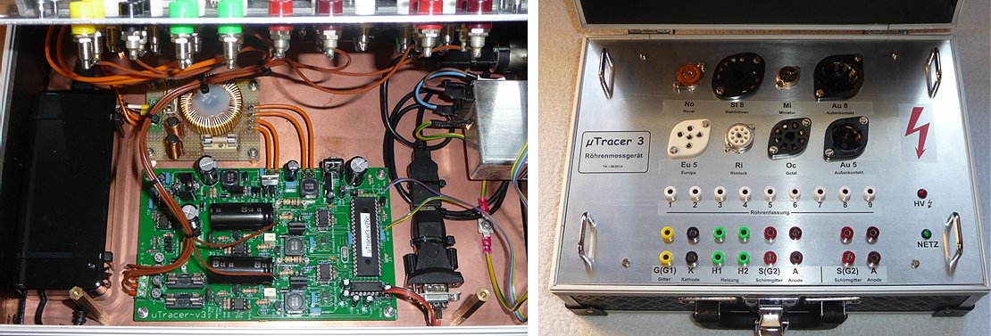
19th of October 2014, Michael Drexler’s uTracer in New York is up and running, and it looks great!
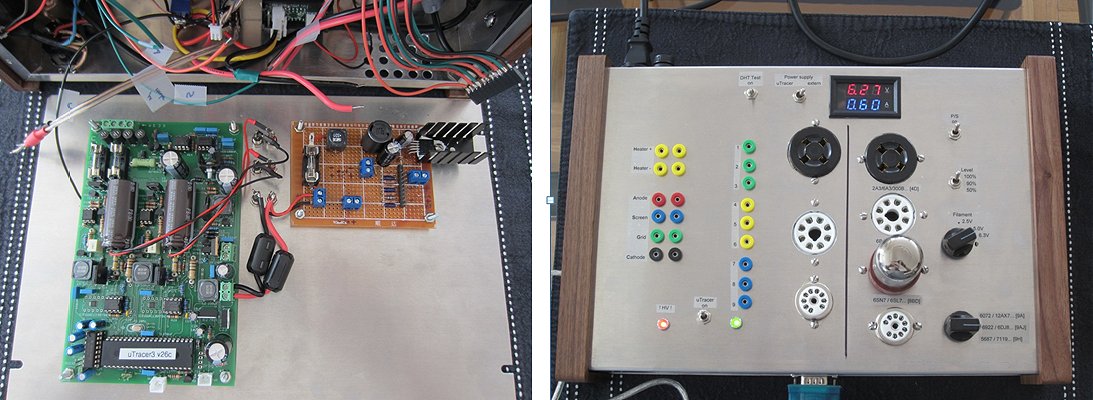
6th of October 2014, Helmut Löwenau’s uTracer is beautifully compact!
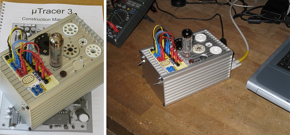
Helmut
29th of September 2014, Eric Bourgeois added a beautiful uTracer to his already impressive laboratory!
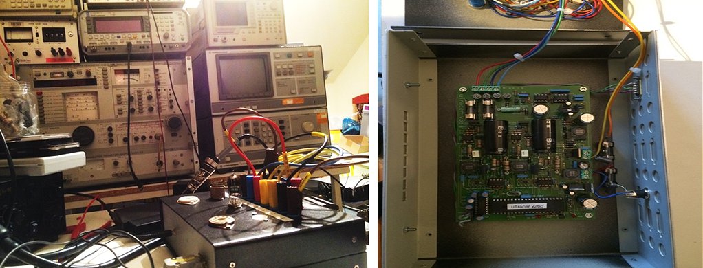
Vous trouverez en pičce jointe quelques photos de ma réalisation.
L’appareil fonctionne parfaitement.
Je teste actuellement la version GUI 3.11.6 et en particulier la mesure de distorsion qui est trčs prometteuse!
Je travaille actuellement ŕ l’amélioration de la linéarité de l’étage d’entrée d’un ancien récepteur de radioamateur ŕ tube.
Amicalement
Eric
The device works perfectly.
I currently testing the Version 3.11.6 GUI and especially the distortion measure is very promising!
I am currently working on improving the input stage linearity old ham radio receiver tube.
Regards
Eric
23rd of September 2014, Kurt Schmid wrote an extensive review of the new QuickTest Features for the “Radiomuseum” forum (in German).
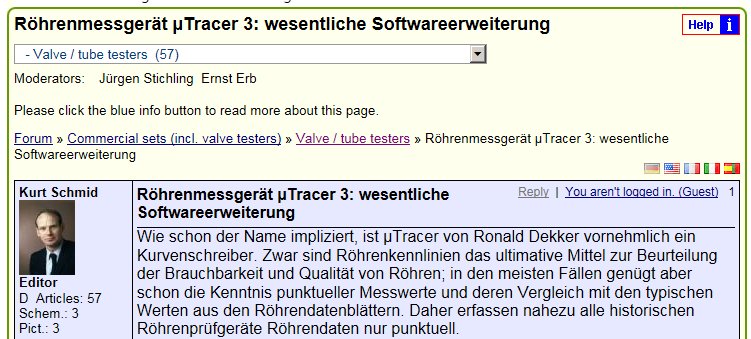
1st of September 2014, Morgan Jones wrote a very favorable review of the uTracer in Linear Audio. For the full article you have to buy the book.
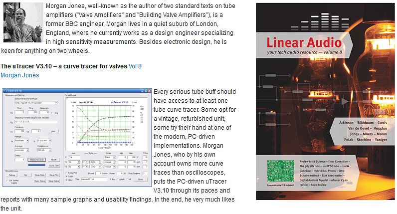
30th of August 2014, Brian Fisher is ready for the winter!
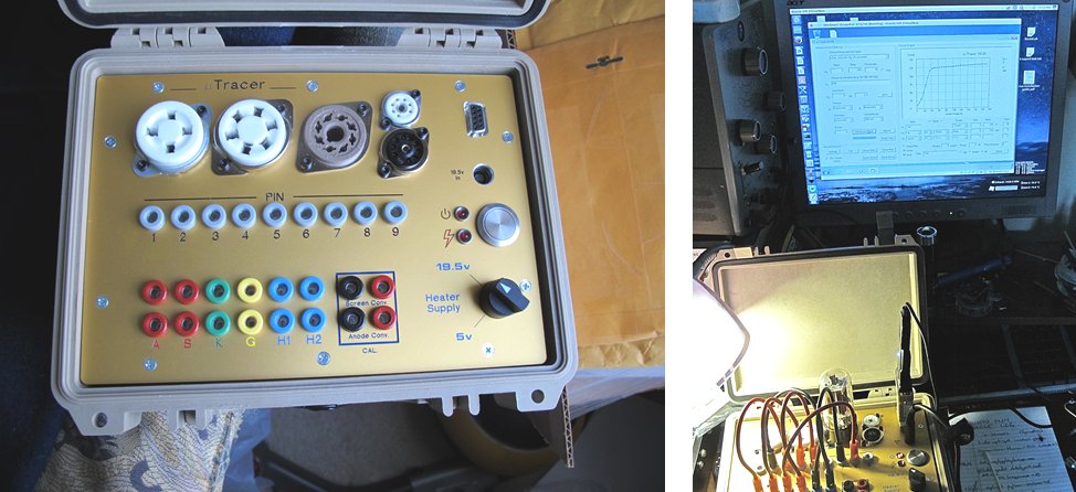
21th of August 2014, Roger Pion’s uTracer is working after a difficult start with a broken BAT86 diode.
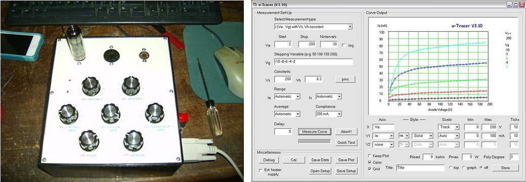
5th of August 2014, Gerald Janisch reported his uTracer working and wrote a very enthusiastic review!
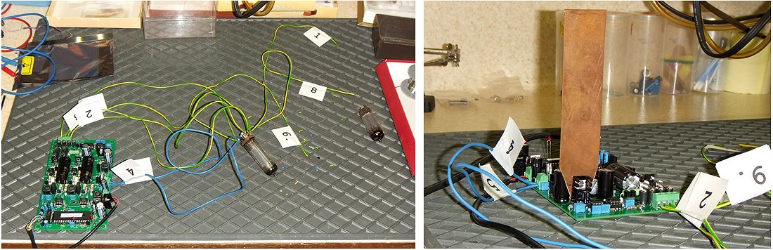
Gerald Janisch
4th of August 2014, Carlos Saavedra made an elegant two box case (be careful for oscillations with long wires!).
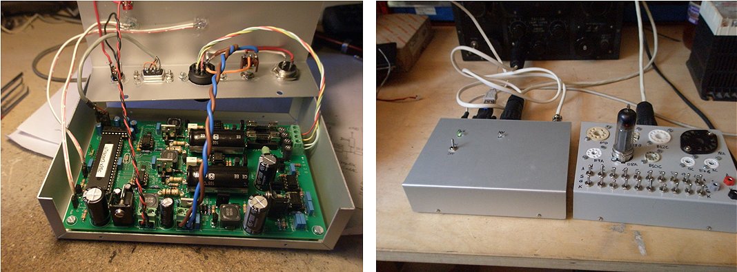
4th of August 2014, Mano reported his uTracer finished with a very enthousiastic testimonial (I wouldn’t have sold my AVO tester!).
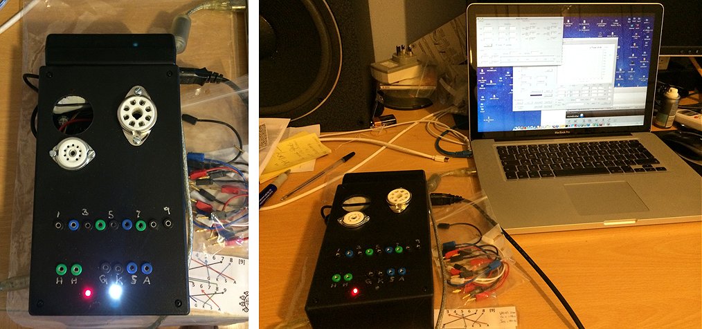
Then in June of this year, I decided to put into a plastic enclosure, fitted the sockets to allow testing of ECC83 and during testing and with a typical school boy error damaged the Anode and Screen Supply output devices. Checking with a DVM they tested fine, however at High Voltage during Valve testing, they leaked. Ronald after contacting; sent me a set of transistors for the output stage free of charge and issue resolved.
The uTracer is now in its enclosure, fully functional in a very simplistic configuration. I removed the RS232 chip and wired in a TTL-USB module so it connects to my Mac osX using wine. The Laptop PSU is stuck to the top of the unit to reduce the clutter.
Some pics enclosed.
As uTracer fits my requirement, I have sold the AVO MK2 and have recommended uTracer3 to anyone who may need a Valve tester as the best/simplistic/cost effective diagnostic tool to have.
Mano
3rd of August 2014, V.T, Mueller sent me an update on the progress of his uTracer.
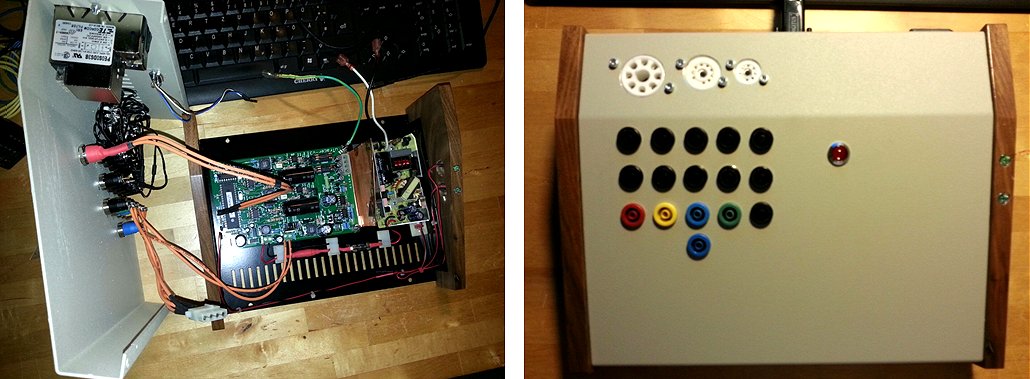
vt
14th of July 2014, Karel Bartos from the Czech Republic used an old communist notice board for the wooden box of his uTracer!
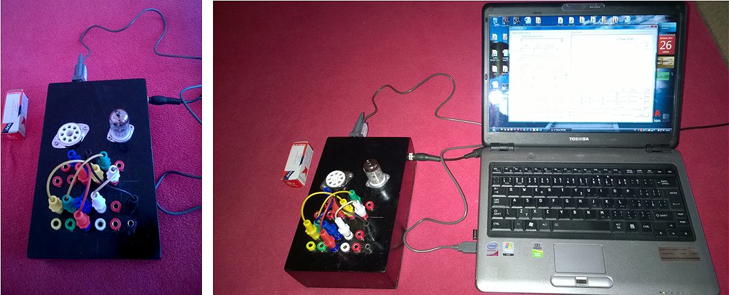
1st of July 2014, André Berwald spent his holiday finishing his uTracer, another satisfied customer!
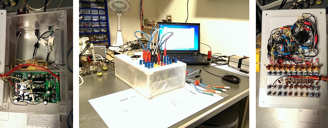
30th of June 2014, Henning Hoeberlin very nicely integrated his uTracer with an old laptop into a single piece of equipment.
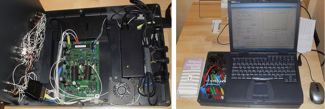
6th of June 2014, Aaron White of Emerald Sound end Vision is very satisfied with his uTracer!
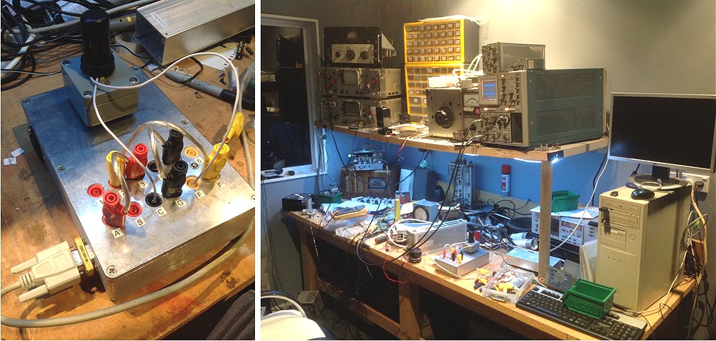
2nd of June 2014, Enrico Munaron’s uTracer looks very slim and professional!
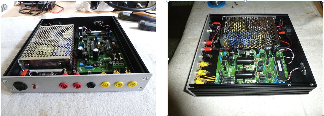
Enrico
8th of April 2014, Chu ( ) send me some pictures of his “vintage” uTracer, and some measurements of a mystery tube: TM15.
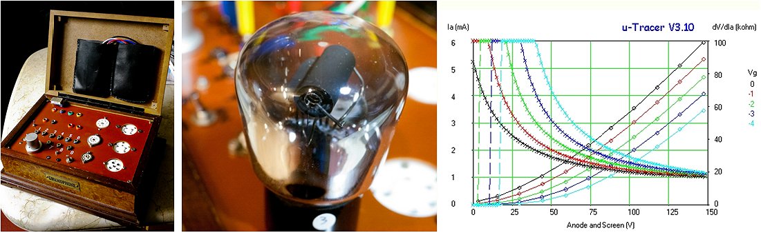
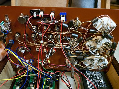 Hello Ronald,
27th of March 2014, Kevin Moulder’s uTracer is absolutely fabulous (I think)
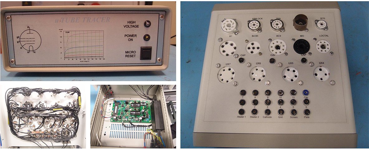
21st of March 2014, Gert Bluemink’s uTracer is simple, but effective!
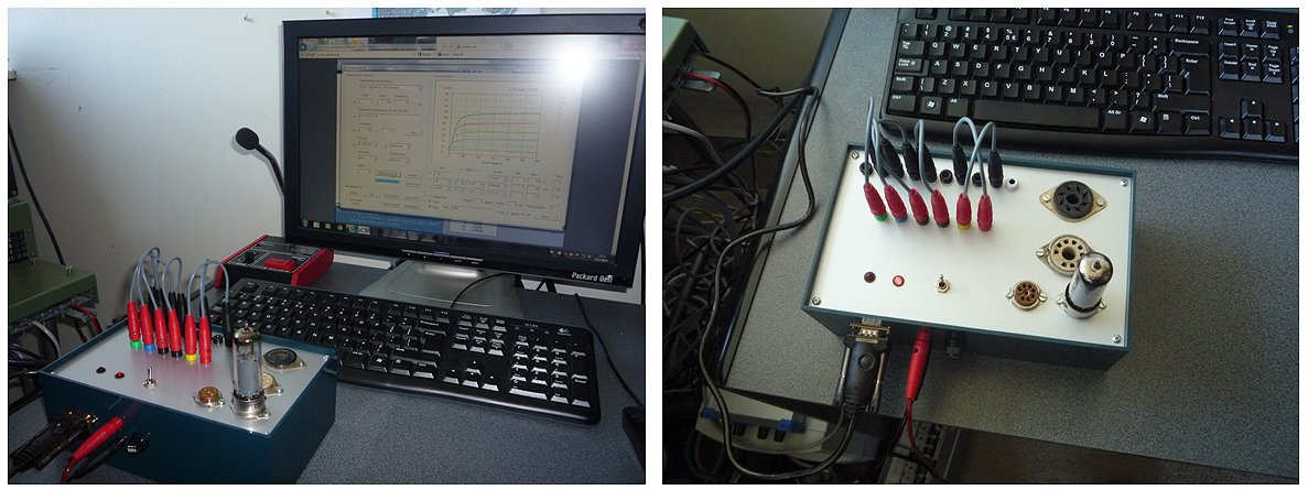
De foto’s tonen even een proefopstelling en ik had nog geen tekst aangebracht op het kastje.
Als radio amateur en liefhebber van buizentechniek heb ik geen uitgebreide buizentester nodig.
De 4 buisvoetjes op de foto volstaan in mijn geval. (en anders kan ik altijd nog een verloopstekker maken).
De 19V haal ik momenteel uit een regelbare voeding.
Eind 80-er jaren heb ik MTS-elektronica gedaan. Opgegroeid met de 8088 microprocessor en buizen waren allang uit de tijd.
Misschien komt daar juist de interesse in die schitterende buizentechniek vandaan, aangezien ik in de modernere technieken al genoeg was onderwezen….
20th of March 2014, Laurent Szymkowiak made a very nice top-plate for his uTracer.
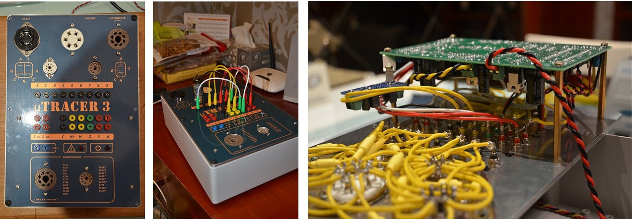
Laurent
5th of March 2014, André Berwald’s uTracer came alive!
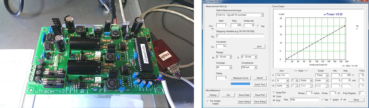
Het bouwen ging voorspoedig en ik heb de handleiding als een perfecte leidraad ervaren.
Het enige wat ik even gemist heb was het insolderen van de header voor het programmeren van de PIC processor (dat had ik natuurlijk samen met de connector for J3 moeten doen in stap 5.18).
Voor de rest ben ik geen gekke dingen tegen gekomen en iedere test en calibratie ging prima.
Nu ga ik nadenken over een geschikte behuizing, eerst nog maar wat lezen op jullie website.
17th of February 2014, Jim Wigley finished his uTracer
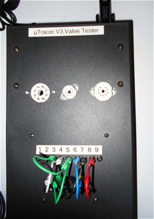
15th of February 2014, Ignacio Zozaya Suárez took the effort to write an extensive review, and sent a few pictures of his uTracer with record amount of sockets.
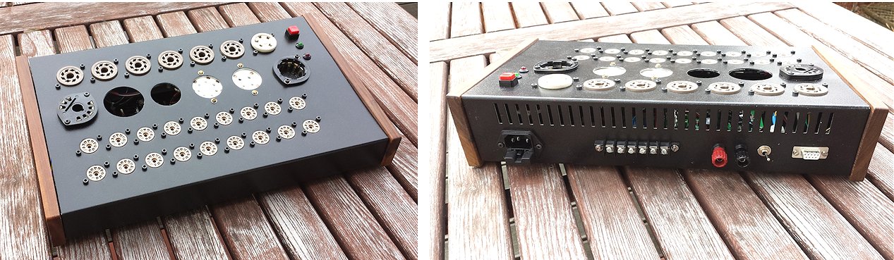
11th of February 2014, Lars-G. Lundelin from Finland finnished his version of the uTracer
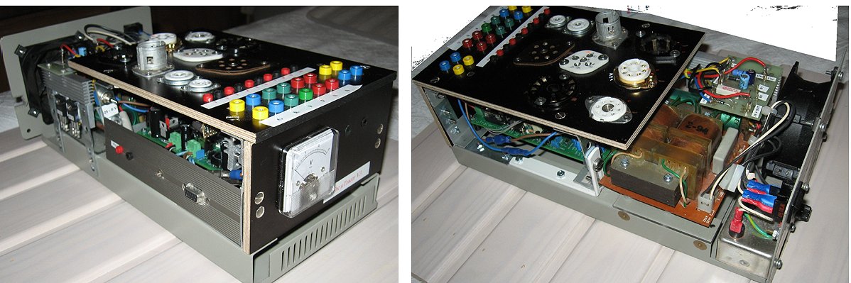
9th of February 2014, Juha Niinikoski sent a few pictures of his very compact uTracer box
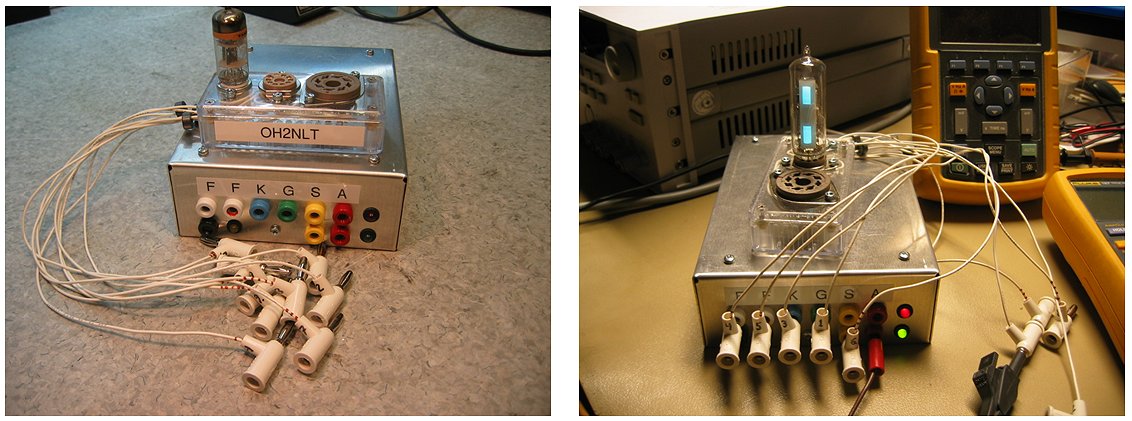
The uTracer is now boxed and working well. Some pictures attached.
2nd of February 2014, Tuukka Kalliokoski from Finland wrote me a very praising review!
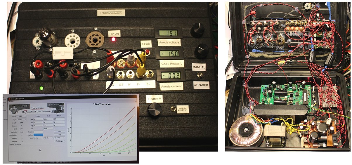
23rd of January 2014, Len Sherman sent a few pictures of his uTracer build
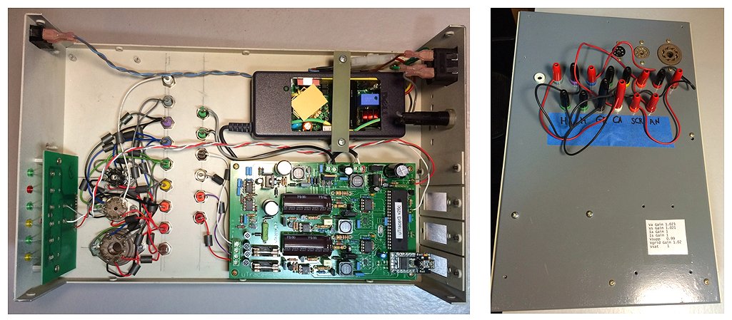
23rd of January 2014, The uTracer of Juha Niinikoski (Finland) has come to life!
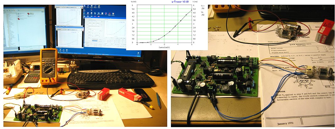
Juha Niinikoski / oh2nlt
15th of January 2014, In five days Anders Magnusson finished his uTracer and boxed up and all!
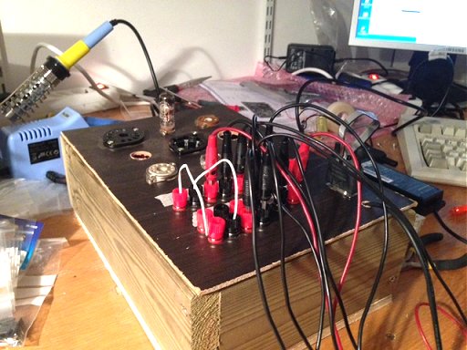
8th of January 2014, Laurent Szymkowiak sent me a nice testimonial!
Dear Ronald,
7th of January 2014, Ian Rodger used the Xmas holidays to finish the case for his uTracer!
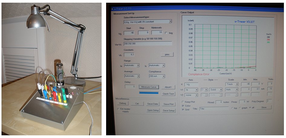
6th of January 2014, Mario St From Italy finished his version of the utracer with direct wired sockets.
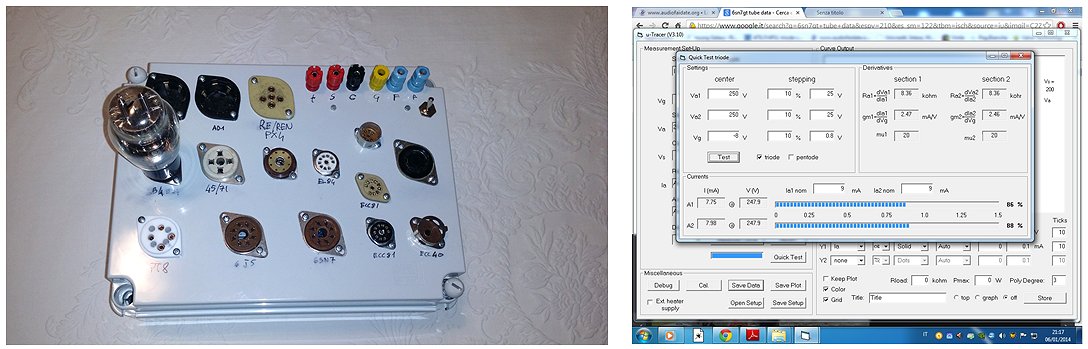
26th of December 2013, Henri Béguin turned his uTracer into an amazing portable instrument!
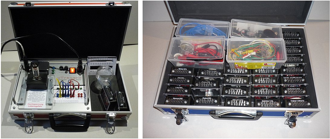
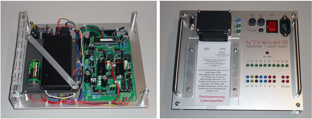
24th of December 2013, Robert Hewitt sent me a few pictures of his nice and tidy uTracer on Christmas eve 2013.
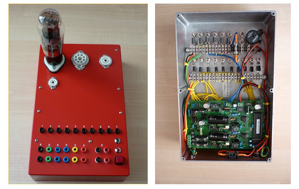
24th of December 2013, Walter Harley from Cafe Walter Audio sent some nice pictures of his uTracer enclosure.
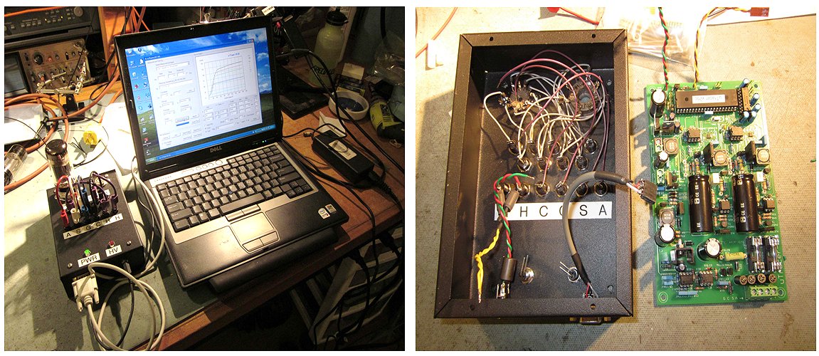
-walter
21st of December 2013, Albrecht Schwaderer turned his uTracer into a beautiful instrument with a definite vintage look!
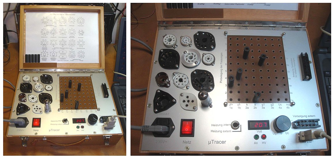
4th of December 2013, Egon Penker sent me a few pictures of his uTracer implementation
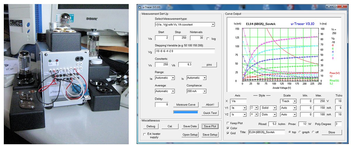
4th of November 2013, Spence Barton reported his uTracer working
2nd of November 2013, Rüdiger Waltz sent me an update on his uTracer
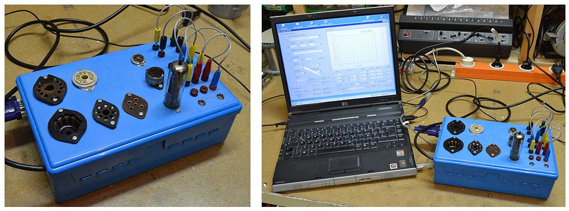
21st of October 2013, Martin Manning finished his very nice and compact uTracer implementation

 I have been making progress on my uTracer after a long delay in selecting and receiving the hardware. The attached pictures show the assembled unit. The tube socket connections are the nine banana jacks arranged in a circle, which makes it easy to translate data sheet pinout diagrams into a patch-cord set-up using standard color codes for the electrodes. A 6V6GT set-up is shown in the photo. Use of stacking banana plugs makes it possible to connect more than one tube pin to any one uTracer terminal, as for simultaneous tracing of a dual triode, or making the g3-cathode connection on an EL34. I went with a direct USB-TTL connection, which is via the 3mm audio jack on the right. Also, you can see that I am locating the two status LED's on the panel, which means a pair of leads for each one with soldered connections to the PCB. Removable connections (like the Tx/Rx) would be a better way to go, but I don't think the spacing of the LED pads is right for that.
20th of October 2013, John Walton wrote an extensive review in the Newsletter of the New Jersey Audio Society (reprinted with permission).
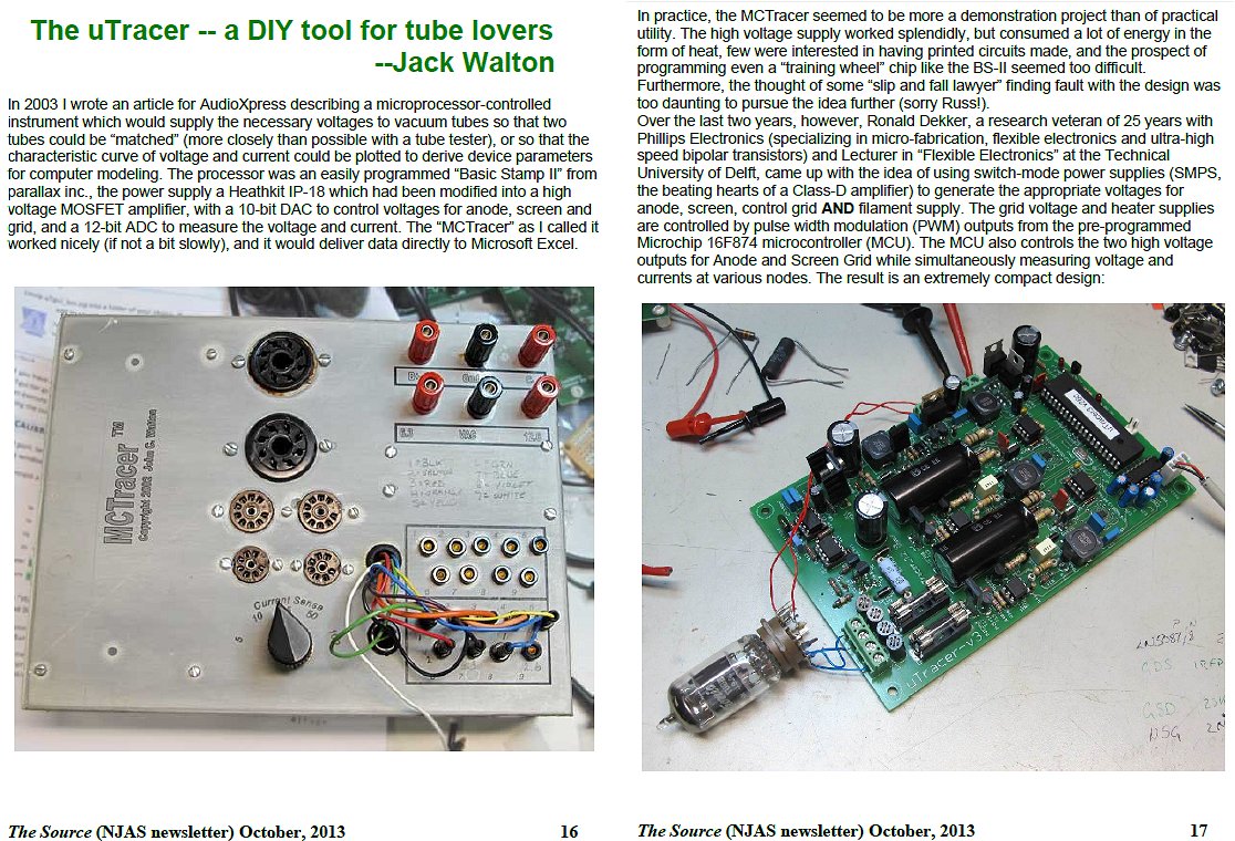
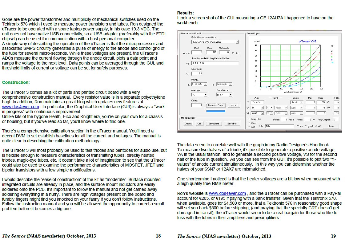
15th of October 2013, Mark Jacobs sent me a few pictures of his stunning uTracer.
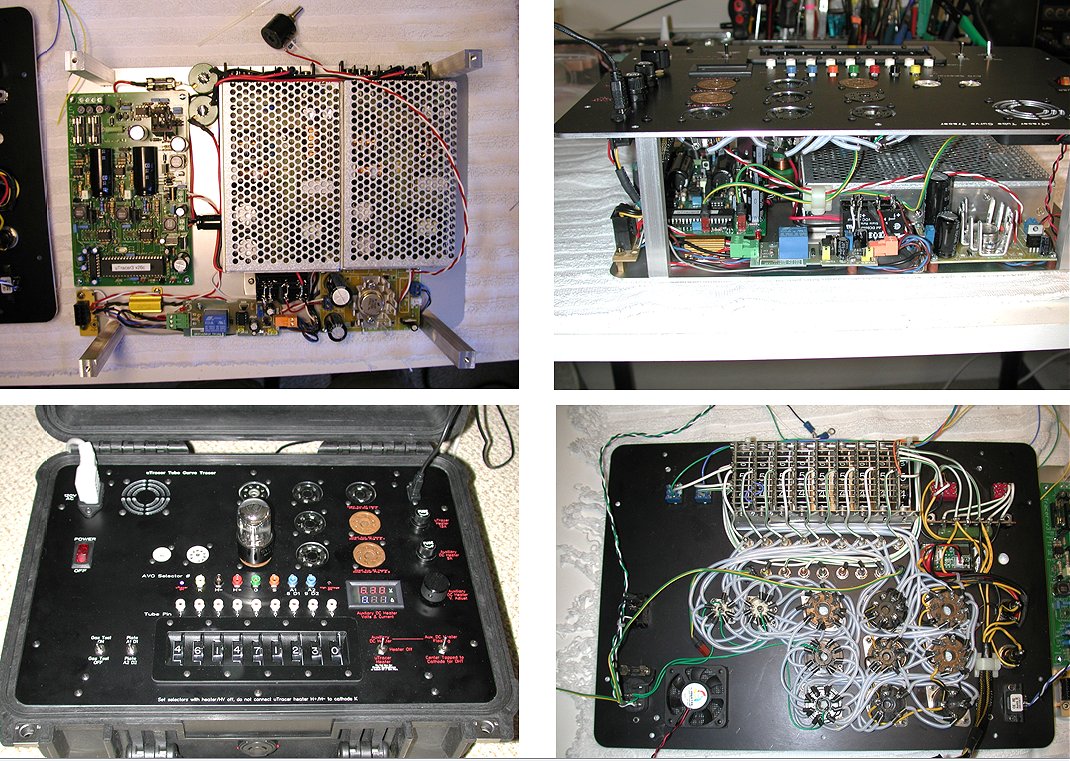
5th of October 2013, Tomas Klika from Prague sent me a few pictures of his awesome uTracer with a DIY matrix board!
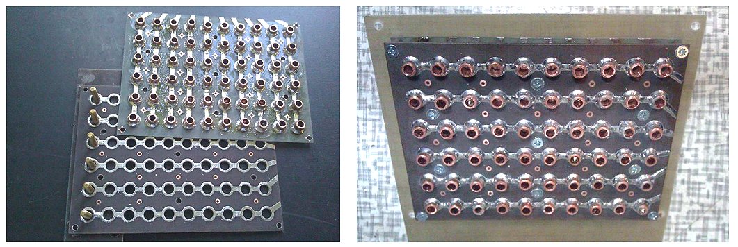
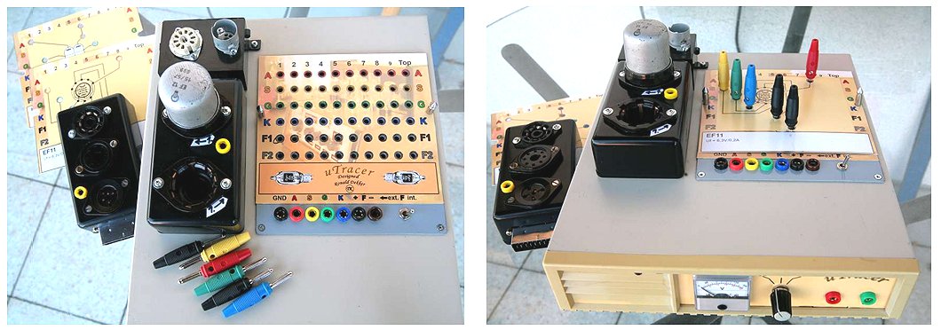
29th of September 2013, Ale Moglia posted a very nice review of the uTracer on his site Bartola Valves.
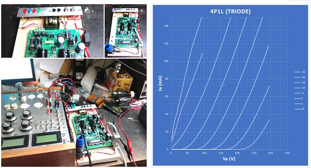
20th of September 2013, Mathieu Melenhorst made a nice portable uTracer.
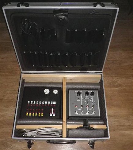 This is my µTracer on the left-hand side in the aluminum case with the Arta measurement box. I decided to use the same measurement connector set-up as Ronald suggested. The only difference is that the four sockets on the lower right side are connected to C13 and C18 to facilitate re-calibration. I included separate sockets at the rear that are in parallel to the power supply.
The Octal and Noval connectors will do (for now).
This is my µTracer on the left-hand side in the aluminum case with the Arta measurement box. I decided to use the same measurement connector set-up as Ronald suggested. The only difference is that the four sockets on the lower right side are connected to C13 and C18 to facilitate re-calibration. I included separate sockets at the rear that are in parallel to the power supply.
The Octal and Noval connectors will do (for now).
19th of September 2013, Peter Buckle send a few pictures of his stunning implementation of the uTracer (the first one in Africa!).
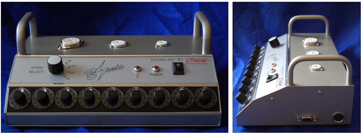
13th of September 2013, Richard Bergquist send a few nice pictures of his uTracer.
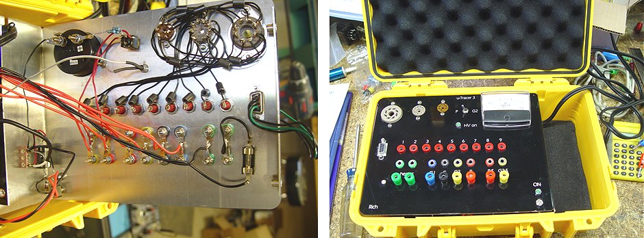
20th of August 2013, Murray Johnson reported: “Another uTracer springs to life!”
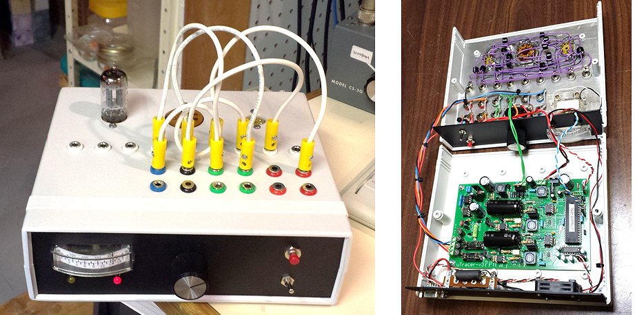
19th of August 2013, Christian Verdier (F6HXH) sent a few snapshots of his uTracer.
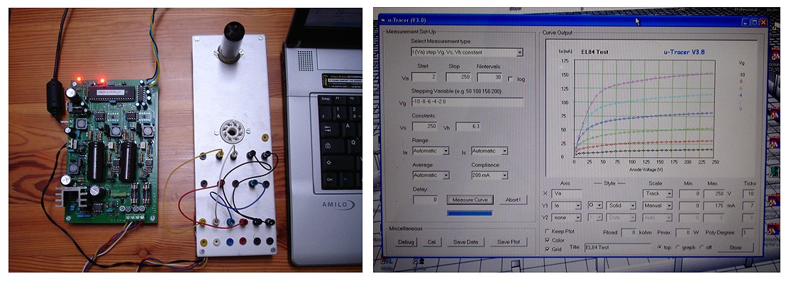
15th of August 2013, Claude Welschbillig sent me a few pictures of his very fine uTracer implementation!
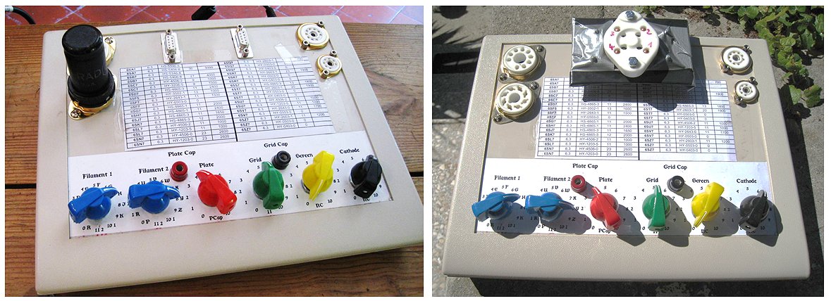
1st August 2013, Ron Soyland, who makes his own replicas of Lee de Forest Audions and other vintage tubes, sent me a few pictures and some comments on his version of the uTracer. Read his report and visit his site or You Tube videos!
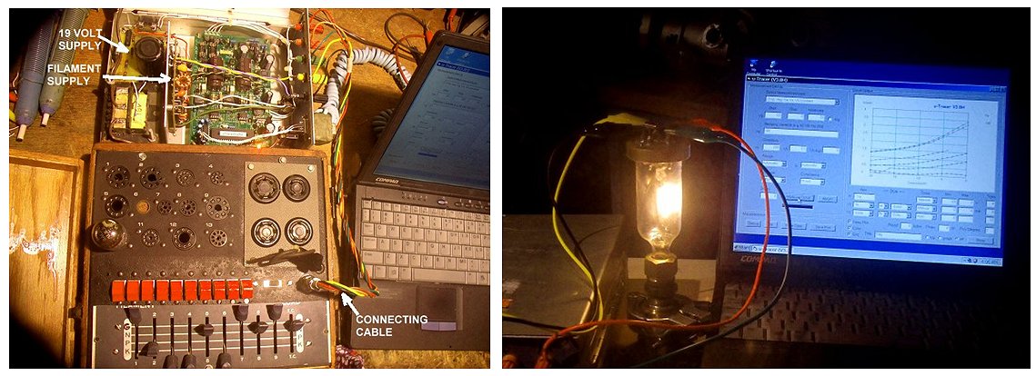
Watch on YouTube how he makes his won Audion Tubes!
Download the circuit diagram of Ron’s low voltage heater supply.
25th July 2013, Peter Håkanson sent me a few pictures of his uTracer. Peter very cleverly uses a special “connector key” to connect different tubes to the uTracer!
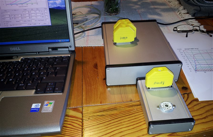
14th July 2013, Paul Barker sent me a few pictures and a very enthusiastic and personal account of his experiences with the uTracer.
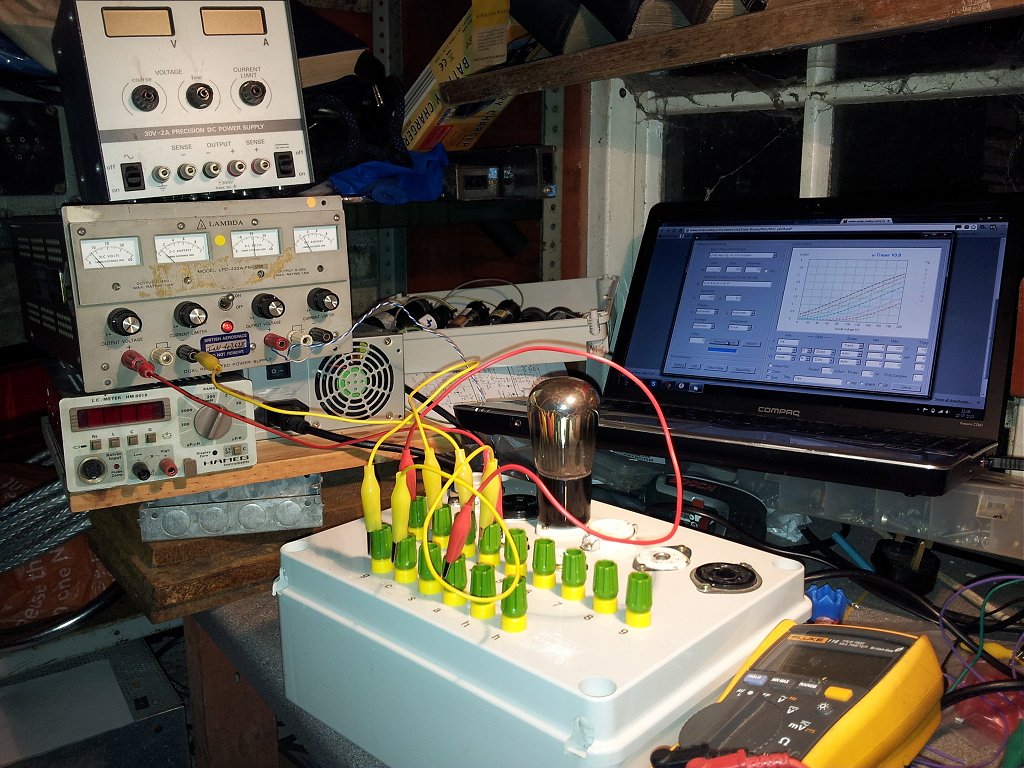
11th July 2013, Mike Watson used a MX-494A/U tube adapter kit as a case for his uTracer, an excellent idea!
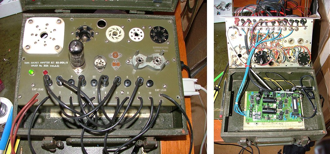
Everything went smoothly and all stages worked first time!
An excellent kit, very clear instructions, I had no trouble at all ...
I just need to build it into my box of valve sockets.
4th July 2013, Marcel Bernards uTracer looks absolutely stunning!
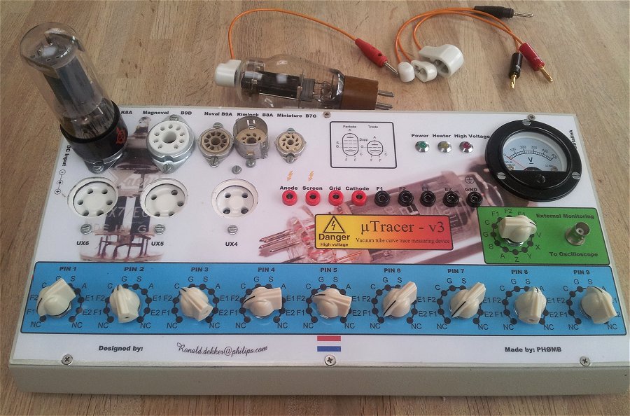
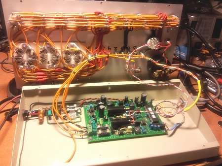 I finished my build last weekend and did some tests and it turned out just great.
28th June 2013, Joachim Mattisson reported his uTracer working:
26th June 2013, Brian finished his version of the uTracer:
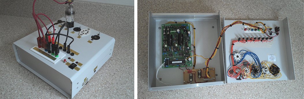
26th June 2013, Leon Glas gave an update of the build of his uTracer (in Dutch):
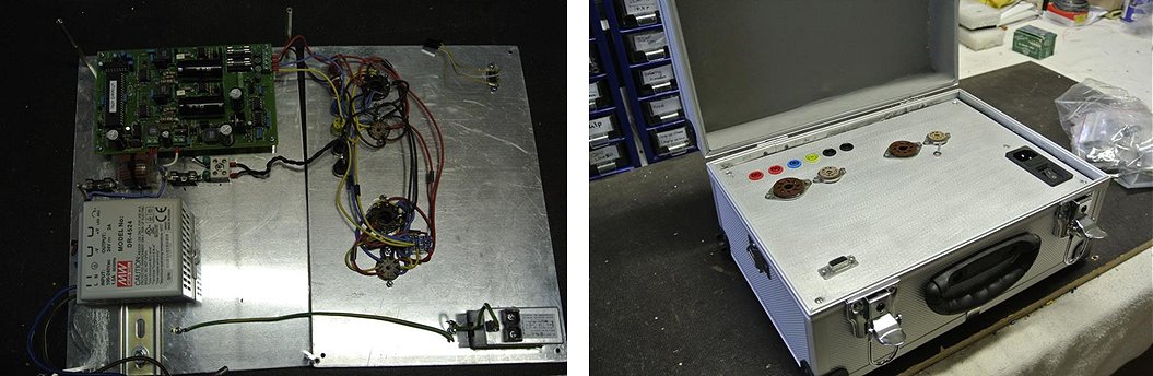
25th June 2013, Thomas Stepanek finished the build of his uTracer in no-time!
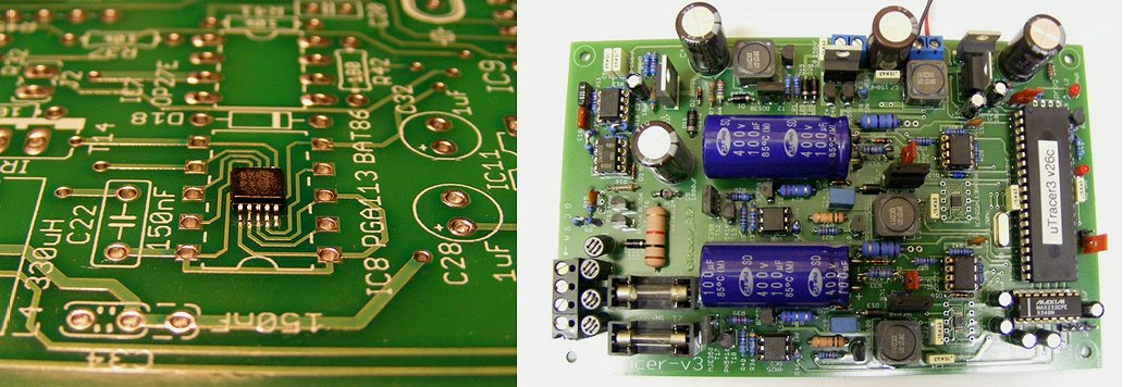
23rd June 2013, Jay Moodley send me a few pictures of his build of the uTracer
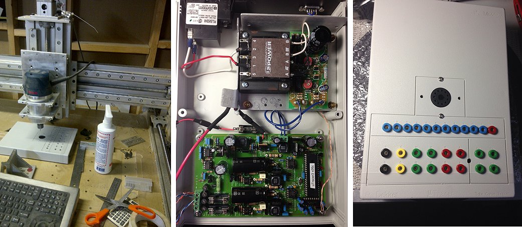
21th June 2013, Michael Watterson, Gave me an update on progress on his uTracer. He certainly broke the record of the number of different sockets!
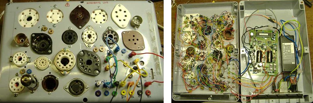
12th May 2013, Fabio Valente sent a few very nice pictures of his uTracer, and a warning!
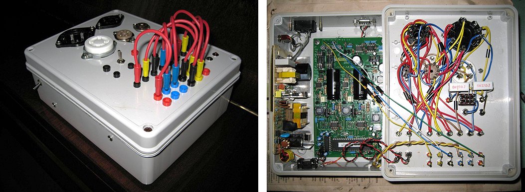
29th April 2013, Jurgen Timpert sent a very nice review of the uTracer his son built!
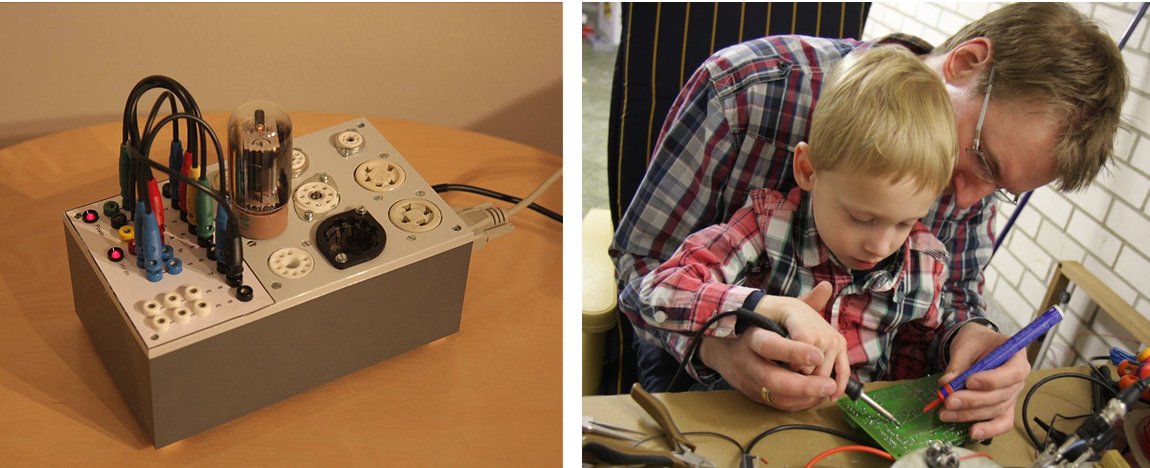
20th April 2013, Marcin Adamski from Norway uses his uTracer to test ancient his radio tubes:
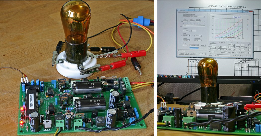
Marcin
18th April 2013, Henning Hoeberlin reported his uTracer working:
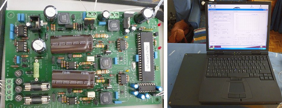
11th April 2013, Achim Korn sent a photo of his fine uTracer case:
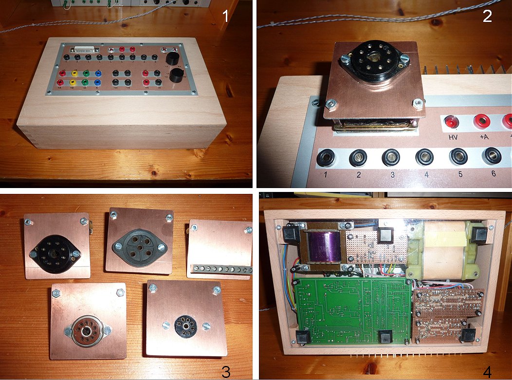
7th April 2013, Francois Bergeret (F6HQZ) sent a photo of his beautiful transparent uTracer case:
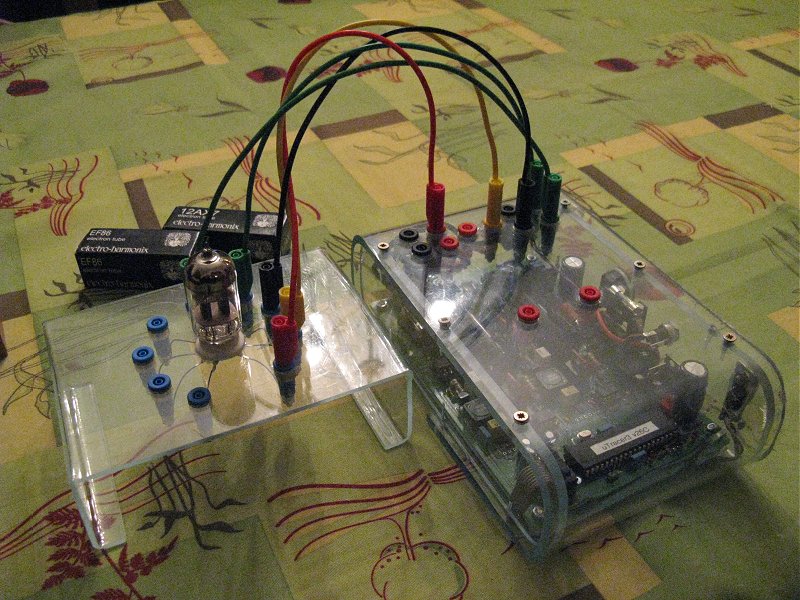
1st April 2013, Heinrich Stummer sent some photo’s of his finished uTracer case:
Now my utracer case assembly is ready.
All the valve holders are located in separate boxes. (avo style wiring inside)
This device works great and is very usable . I took some traces of old tubes laying around in my shack.
Thank you for the excellent kit and construction manual.
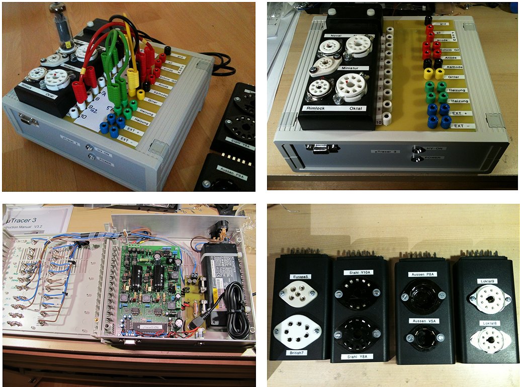
25th March 2013, After a long journey through Russia, Alex’s uTracer kit reached him after which is was finished in no-time!
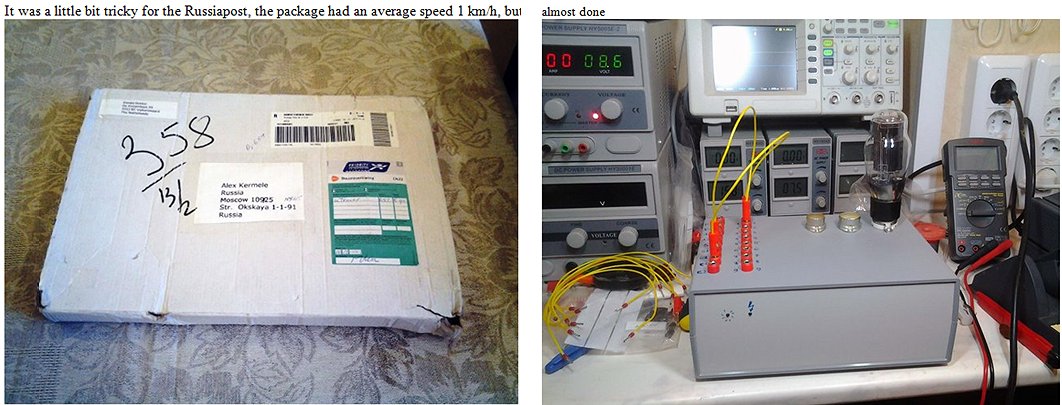
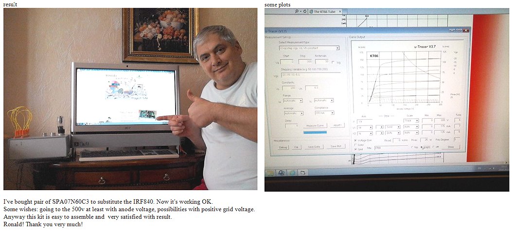
17th March 2013, Francois Bergeret’s (France) uTracer is up and running:
16th March 2013, Jerry from the US finished his uTracer:
Attached are some photos for you.
You may publish them as you wish.
I was testing a 6AU6 in the photos.
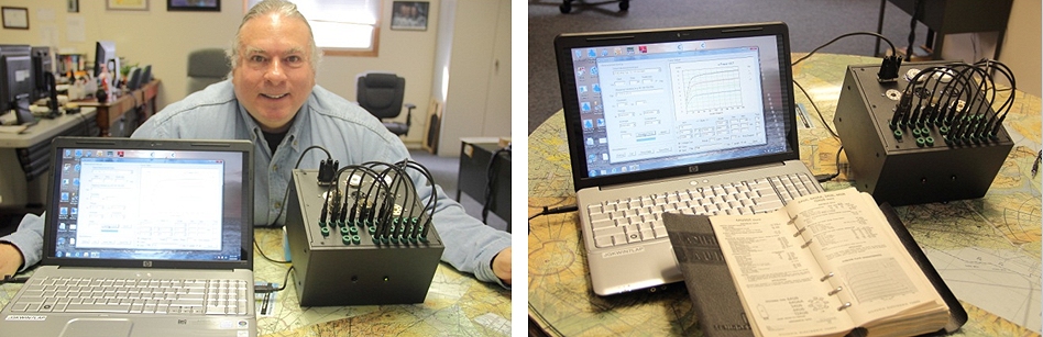
16th March 2013, Jim MacWilliams from the US sent a few pictures:
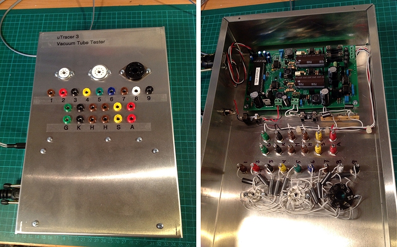
13th March 2013, Kevin Kennedy (US) took the time to write an extensive review:
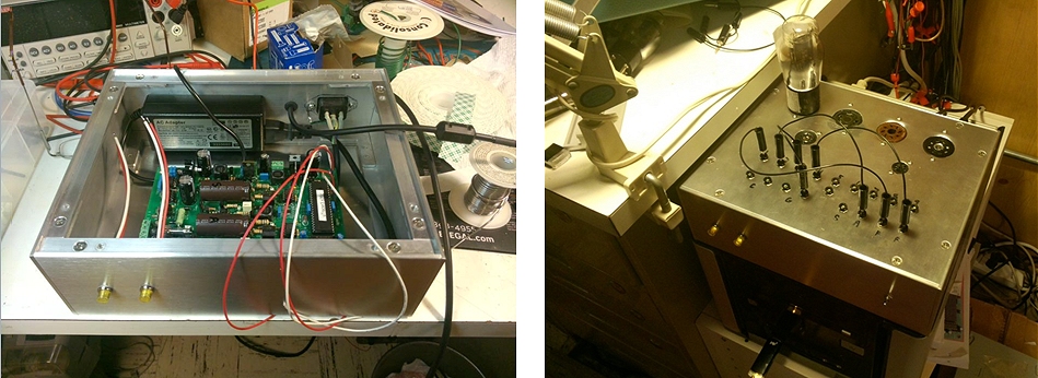
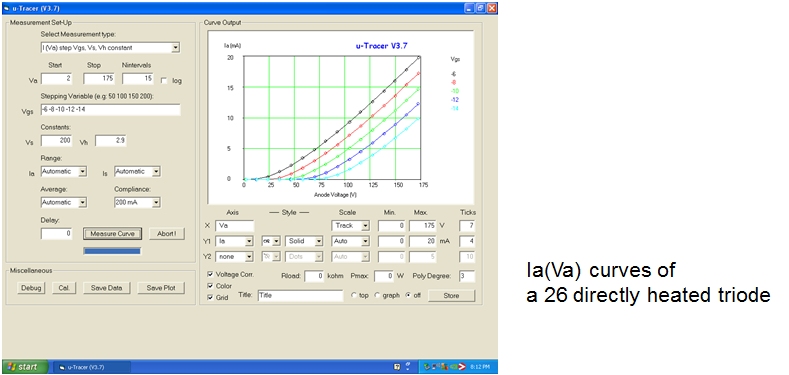
12th March 2013, Heinrich Stummer finished the build of his uTracer :
The building was much easier than I expected.
Build and test, all works smooth.
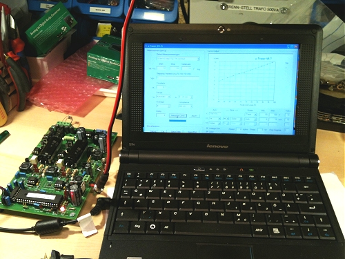
4th March 2013, Richard Zajkowski (France) sent a few pictures of his finished uTracer:
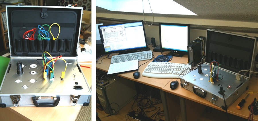
3rd March 2013, Jerome Kahn wrote:
25th Februari 2013, Have a look at the magnificent realization of the uTracer by Ilpo Leppänen (Finland).
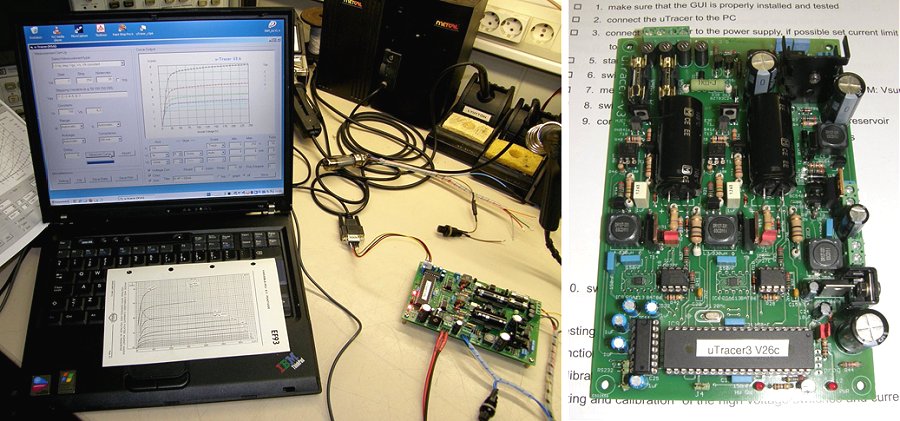
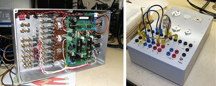
24th Februari 2013, Rüdiger Waltz uses his uTracer to test his own Homemade tubes !!
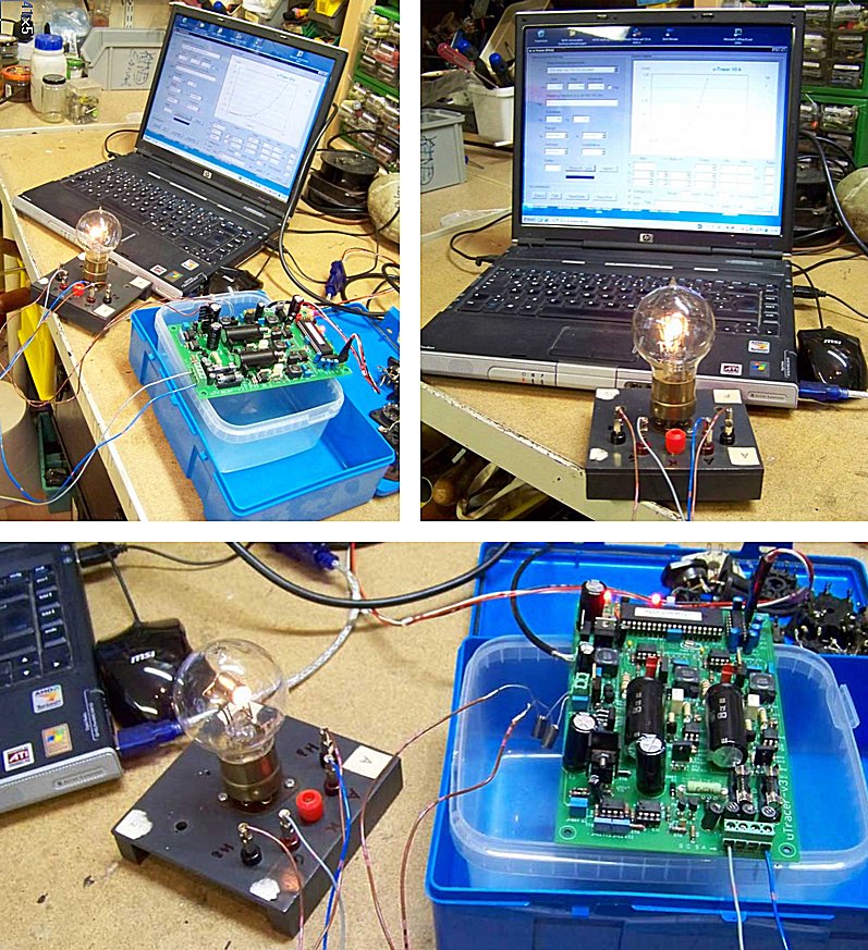
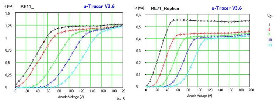
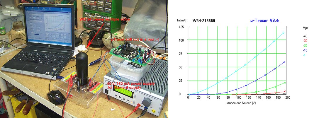
19th Februari 2013, Klaus Ortwein from Cologne from Germany send a few pictures of his beautiful implementation of the uTracer
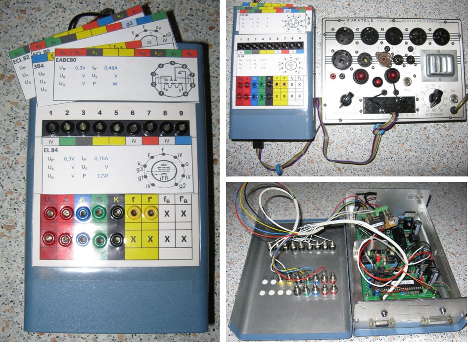
14th Februari 2013, Ari Huju send a few pictures of his implementation of the uTracer:
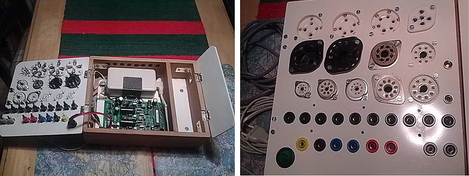
13th Februari 2013, James Hill send an update:
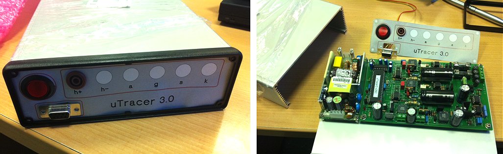
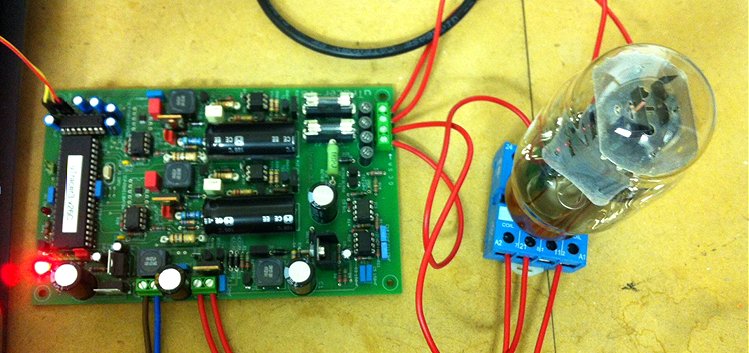
13th Februari 2013, Bill van Dijk (Canada) send an update:
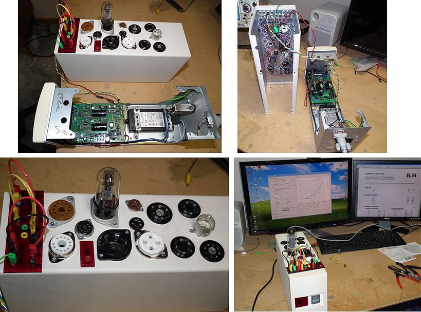
12th Februari 2013, Nick Barton from Black Magic Amplifiers wrote:
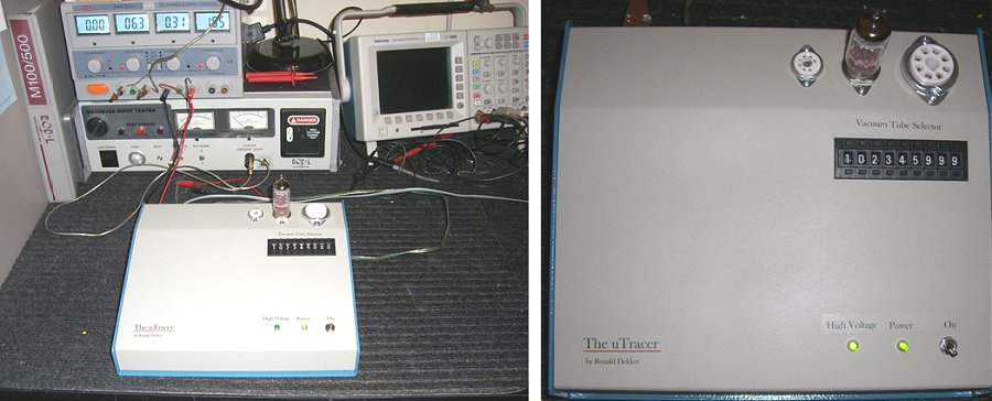
25th Januari 2013, John Hayes finished his uTracer:
8th Januari 2013, Yves Dupont shares his experiences with the uTracer:
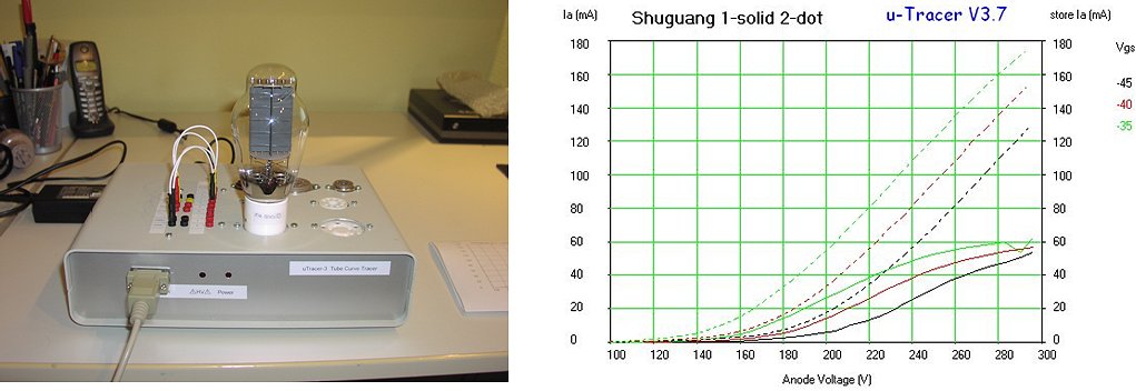
Building the kit was a breeze due to the excellent construction manual.
With the risk of repeating myself: The uTracer hardware design is outstanding.
It’s a tremendously useful tool, thanks for sharing with the DIY-community your work and your time.
Both were working, the AVO Mk4 indicated a lower emission for one of the two.
But the uTracer shows that one is really a unusable dud and the emission for the other tube starts to nose-dive a bit on higher currents.
In short: I’m *pleased*.
1st Januari 2013, Michael Schlör from Germany finished his uTracer during the Christmas holidays, he writes:
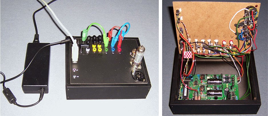
Der Zusammenbau und schrittweise Abgleich verlief dank hervorragendem Manual problemlos. Ich entschied mich bei den Verbindungen zu den Röhrenfassungen für steckbare Kurzschlussverbinder. Die Buchsen vom µTracer habe ich ähnlich wie im Handbuch beschrieben doppelt angelegt. Die Verbindungen zwischen den Röhrenfassungen sind größtenteils mit Breitbanddrosseln ausgeführt. Anfangs hatte ich auch in beide Heizleitungen jeweils RFI Drosseln gelegt, doch stellte sich beim ersten Test mit einer EL84 heraus, dass die Heizung deutlich zu niedrig war. Die Röhre erreicht nicht ihren Ia Wert, den sie mit externer Heizung am µTracer erreichte. Der Unterschied war signifikant. Die Breitbanddrosseln reagierten offensichtlich schon deutlich bei der 19kHz gepulsten Heizspannung. Nach Entfernen der RFI Drosseln aus dem Heizkreis sind praktisch keine Messunterschiede mehr zwischen interner und externer Röhrenheizung feststellbar. Ich benutzte den Ia Wert der EL84 mit externer Heizung und kalibrierte so mittels Usupp Schieber die interne Röhrenheizung bei meinem µTracer.
31st December 2012, Nick de Smith from Kent, England, finished his uTracer on old year’s night:
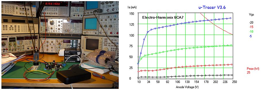
31st December 2012, Joris Weijters from Holland send a few pictures of his version of the uTracer:
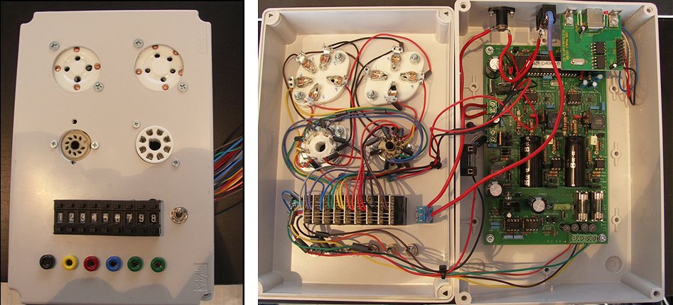
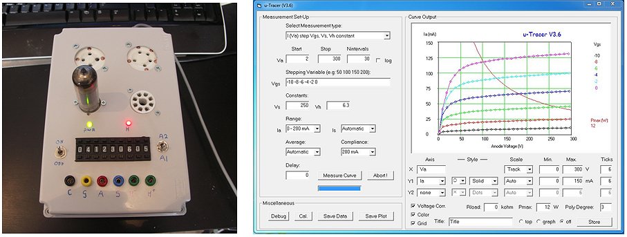
9th December 2012, Lauri Salasmaa from Finland sent a few pictures from his version of the uTracer:
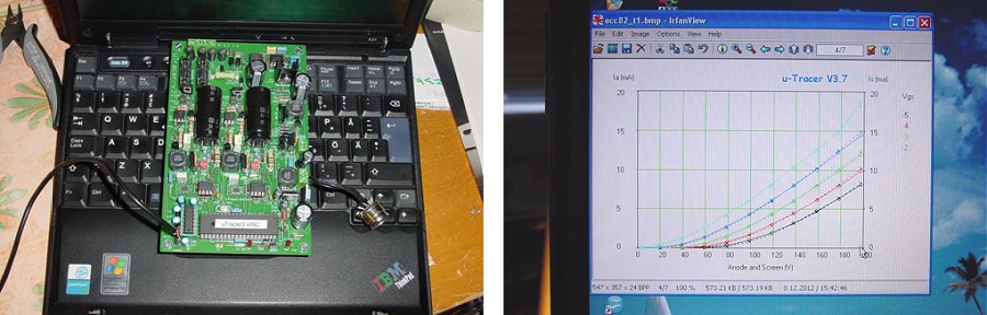
7th December 2012, Pascal from Belgium made his own uTracer on Perfboard:
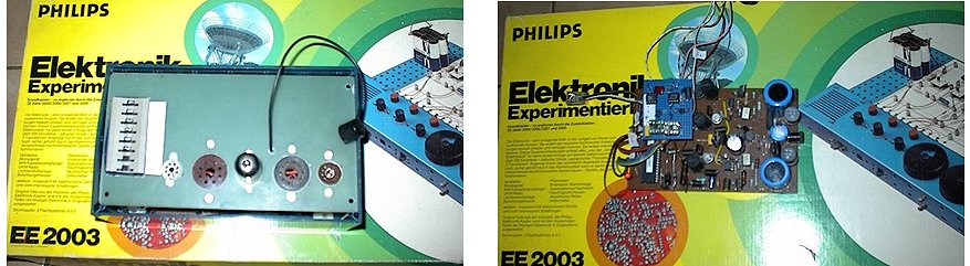
1st December 2012, Kurt Schmid posted an extensive (German) review on the Radiomuseum forum (click here)
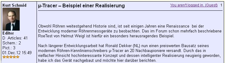
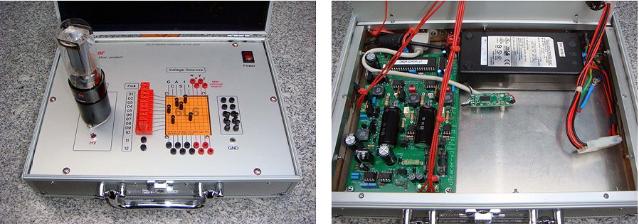


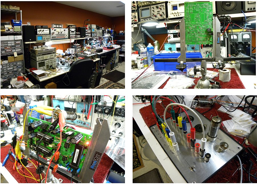
November 24, 2012 Derk Reefman from the U.S.A.:
I have been facinated in tubes and tube circuits since my childhood - most likely because my grandfather had been working with the dutch "PTT" (post and telegraph and telephony), and later my dad, too. I have been the exception studying chemistry and physics...
Anyway, I have a hobby in building hifi audio tube amplifiers. When it comes to building amps with distortion figures below -100 dB and bandwidths of 50 kHz (I am a super audio fan!), knowing the tube's characteristics is paramount. I have long been searching for something simple but complete that could give me a tube characteristic that I could parametrize and load in spice (or your favourite circuit simulator). And now I have found it! Ronald's kit for a tube tester/analyzer was really easy to build, had a very good manual for testing... What can one wish more?
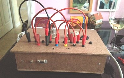
November 21, 2012 Bill van Dijk from Canada wrote:
Hello Ronald,
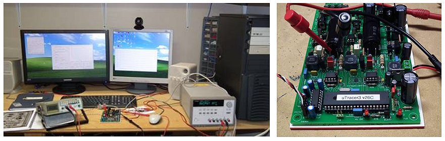
November 19, 2012 Robin Simmons from the UK wrote:
I've been looking for a 'valve tester' ever since starting my own company repairing and modifying electronic equipment such as guitar and hi-fi amps. The vast majority of existing equipment that I have seen so far is either totally inadequate in terms of functionality or else over priced. In fact, usually both and only available second hand when they're already worn out. Not any more! Enter the uTracer designed by Ronald Dekker. I have been following this project for some time and jumped at the opportunity to buy a kit and build my own tester. Being an Electronics Engineer by trade this held no obstacles for me but even if you're not then Ronald provides all the information you need to build a uTracer with only a few simple tools and a bit of patience.
November 18, 2012 Georg Beckmann posted a review on the uTracer on the Radiomuseum forum (click here)
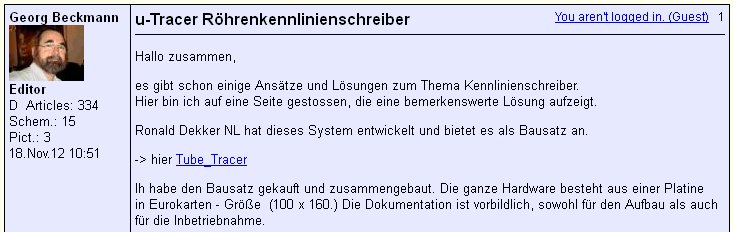
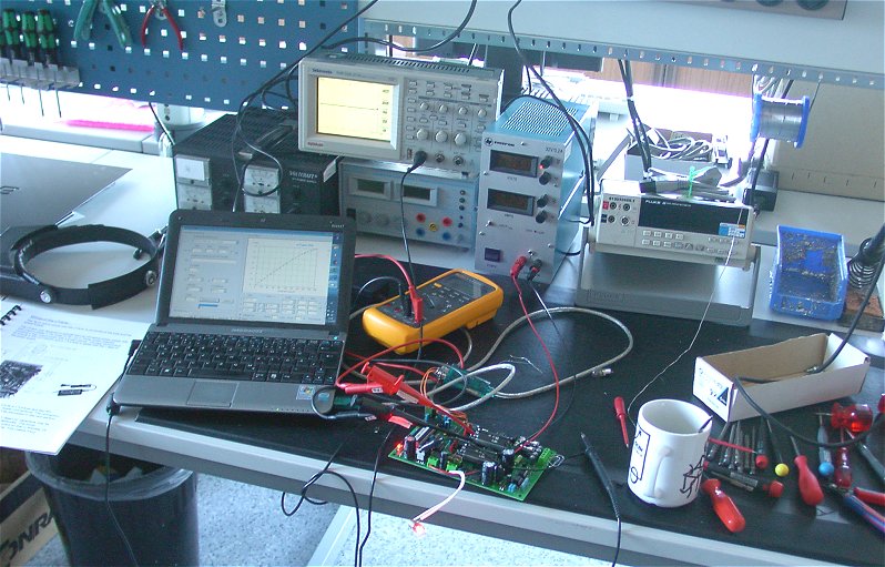
November 8, 2012 Lourens Koopmans from Holland:
After receiving the uTracer3 kit from Ronald, I immediately started assembling the PCB, the build is straight forward, all steps are clearly described and all separate parts of the uTracer3 are individually tested. The testing and calibration was no issue, I only made a small mistake measuring the grid voltage referenced to ground instead of the cathode.
29 October 2012, Roger from Germany:

18 September 2012, Kurt Schmid posted an extensive (German) review on the Radiomuseum forum (click here)
11 September 2012, Roger from Germany wrote:
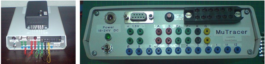
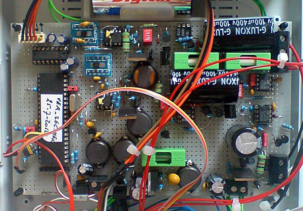
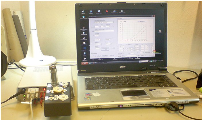
previous page
next page


Deel 1
Part 1
Teil 1
1čre Partie
Deel 2
Part 2
Teil 2
2e Partie
Deel 3
Part 3
Teil 3
3e Partie
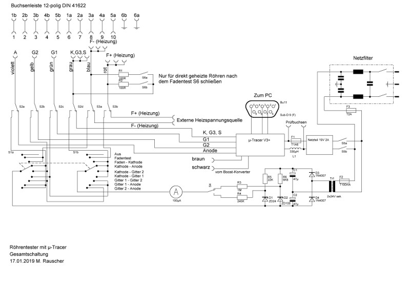